Sign In
Upload
Manuals
Brands
Circutor Manuals
Inverter
SVGm
Circutor SVGm Static Var Generator Manuals
Manuals and User Guides for Circutor SVGm Static Var Generator. We have
3
Circutor SVGm Static Var Generator manuals available for free PDF download: Instruction Manual
Circutor SVGm Instruction Manual (200 pages)
Static var generator
Brand:
Circutor
| Category:
Inverter
| Size: 37 MB
Table of Contents
Español
5
Contenido - Contents
3
Precauciones de Seguridad
4
Limitación de Responsabilidad
4
Table of Contents
5
Contenido
5
Histórico de Revisiones
7
Símbolos
7
1 Comprobaciones a la Recepción
8
Protocolo de Recepción
8
Transporte y Manipulación
8
Almacenaje
10
2 Descripción del Producto
11
3 Instalación del Equipo
15
Recomendaciones Previas
15
Emplazamiento
16
Requisitos de Ventilación
16
Almacenamiento Durante un Largo Periodo
18
Instalación
18
Svgm TIPO MURAL
18
Svgm TIPO RACK
19
Svgm TIPO ARMARIO
20
Conexión
21
Bornes del Equipo
23
Svgm TIPO MURAL: Svgm-3WF-XXXM y Svgm-4WF-XXXM
23
Svgm TIPO RACK: Svgm-3WF-100R y Svgm-4WF-069R
25
Svgm TIPO ARMARIO: Svgm-3WF-XXXC-480 y Svgm-4WF-XXXC-400
26
Svgm TIPO ARMARIO: Svgm-3WF-XXXC-690 y Svgm-4WF-XXXC-550
28
Esquemas de Conexionado
30
Conexión a 4 Hilos y Medida de Corriente en el Lado de Red
30
Conexión a 4 Hilos y Medida de Corriente en el Lado de Carga
31
Conexión a 3 Hilos y Medida de Corriente en el Lado de Red
32
Conexión a 3 Hilos y Medida de Corriente en el Lado de Carga
33
Conexión a 3 Hilos y 2 Transformadores de Corriente en el Lado de Red
34
Conexión a 3 Hilos y 2 Transformadores de Corriente en el Lado de Carga
35
CONEXIONADO de 2 a 100 Svgm en PARALELO
36
Conexión de Equipos Individuales
37
Conexión de Armarios
38
4 Funcionamiento
39
Principio de Funcionamiento
39
Media Tensión
40
Autodiagnóstico
40
Protección Térmica
40
Display
41
Área Superior
42
Área Central
42
Área Inferior
42
5 Puesta en Marcha
44
6 Visualización
45
Pantalla Principal
45
Equipo Único O Maestro
45
Equipo Esclavo
46
Tensión, Corriente y Frecuencia
47
Potencia y Cos ɸ de Red
47
Potencia y Cos ɸ de Carga
48
Fasores de Red
49
Fasores de Carga
49
Alarmas
50
Advertencias
51
Temperatura
54
Comunicaciones Ethernet
54
Información del Equipo
55
Estado de Los Equipos Esclavos
56
7 Configuración
57
Idioma
58
Especificaciones del Equipo
58
Equipos Instalados
59
Límites de Trabajo
60
Cos Φ
61
Configuración de Los Transformadores
62
Media Tensión
63
Comunicaciones Ethernet
64
Comunicaciones Rs-485
64
Fecha / Hora
65
Password
66
Guardar Datos
66
8 Comunicaciones Rs-485
67
Conexionado
67
Protocolo
68
Ejemplo de Pregunta Modbus
68
Mapa Modbus
68
9 Comunicaciones Ethernet
72
Conexión
72
Página Web
72
10 Mantenimiento
74
Mantenimiento Estándar
74
Ventiladores de Refrigeración
76
CAMBIO de VENTILADORES de REFRIGERACIÓN: Svgm de 20.7 y 30 Kvar
76
CAMBIO de VENTILADORES de REFRIGERACIÓN: Svgm de 41.4 y 60 Kvar
79
CAMBIO de VENTILADORES de REFRIGERACIÓN: Svgm Tipo RACK
82
CAMBIO de VENTILADORES de REFRIGERACIÓN: Svgm de 69 y 100 Kvar MURAL
85
CAMBIO de VENTILADORES de REFRIGERACIÓN: Svgm TIPO ARMARIO
86
MANTENIMIENTO de LOS PROTECTORES de SOBRETENSIÓN: Svgm-3WF-XXXC-690 Ysvgm-4WF-XXXC-550
87
11 Características Técnicas
88
12 Servicio Técnico
98
13 Garantía
98
14 Certificado Ce
99
English
103
Disclaimer
102
Safety Precautions
102
Contents
103
Revision Log
105
Symbols
105
1 Verification Upon Reception
106
Reception Protocol
106
Transport and Handling
106
Storage
108
2 Product Description
109
3 Device Installation
113
Preliminary Recommendations
113
Installation Location
114
Ventilation Requirements
114
Storage for Long Periods
116
Installation
116
WALL-TYPE Svgm
116
RACK-TYPE Svgm
117
CABINET-TYPE Svgm
118
Connection
119
Device Terminals
121
WALL-TYPE Svgm: Svgm-3WF-XXXM and Svgm-4WF-XXXM
121
RACK-TYPE Svgm: Svgm-3WF-100R and Svgm-4WF-069R
123
CABINET-TYPE Svgm: Svgm-3WF-XXXC-480 and Svgm-4WF-XXXC-400
124
CABINET-TYPE Svgm: Svgm-3WF-XXXC-690 and Svgm-4WF-XXXC-550
126
Connection Diagrams
128
4-Wire Connection and Current Measurement on the Mains Side
128
4-Wire Connection and Current Measurement on the Load Side
129
3-Wire Connection and Current Measurement on the Mains Side
130
3-Wire Connection and Current Measurement on the Load Side
131
3-Wire Connection and 2 Current Transformers on the Mains Side
132
3-Wire Connection and 2 Current Transformers on the Load Side
133
PARALLEL CONNECTION of 2 to 100 Svgm
134
Connecting Individual Devices
135
Connecting Cabinets
136
4 Operation
137
Operating Principle
137
Medium Voltage
138
Self-Diagnosis
138
Thermal Protection
138
Display
139
Upper Area
140
Central Area
140
Lower Area
140
5 Start-Up
142
6 Display
143
Main Screen
143
Device Single or Master
143
Device Slave
144
Voltage, Current and Frequency
145
Power and Cos ɸ of Mains
145
Power and Cos ɸ of Load
146
Mains Phasors
147
Load Phasors
147
Alarms
148
Warnings
149
Temperature
152
Ethernet Communications
152
Device Information
153
Slave Device Status
154
7 Configuration
155
Language
156
Device Specifications
156
Installed Devices
157
Operating Limits
158
Cos Φ
159
Transformer Configuration
160
Medium Voltage
161
Ethernet Communications
162
Rs-485 Communications
162
Date / Time
163
Password
163
Save Data
164
8 Rs-485 Communications
165
Connections
165
Protocol
166
Example of Modbus Query
166
Modbus Map
166
9 Ethernet Communications
170
Connection
170
Web Site
170
10 Maintenance
172
Standard Maintenance
172
Cooling Fans
174
CHANGE of COOLING FANS: Svgm of 20.7 and 30 Kvar
174
CHANGE of COOLING FANS: Svgm of 41.4 and 60 Kvar
177
CHANGE of COOLING FANS: Svgm Type RACK
180
CHANGE of COOLING FANS: Svgm of 69 and 100 Kvar WALL
183
CHANGE of COOLING FANS: CABINET TYPE Svgm
184
MAINTENACE of SURGE PROTECTIVE DECIVES: Svgm-3WF-XXXC-690 and Svgm-4WF-XXXC-550
185
11 Technical Features
186
12 Technical Service
196
13 Guarantee
196
14 Ce Certificate
197
Advertisement
Circutor SVGm Instruction Manual (148 pages)
Static var generator IP54
Brand:
Circutor
| Category:
Inverter
| Size: 12 MB
Table of Contents
Español
5
Contenido - Contents
3
Precauciones de Seguridad
4
Limitación de Responsabilidad
4
Table of Contents
5
Contenido
5
Histórico de Revisiones
7
Símbolos
7
1 Comprobaciones a la Recepción
8
Protocolo de Recepción
8
Transporte y Manipulación
8
Almacenaje
9
2 Descripción del Producto
10
3 Instalación del Equipo
12
Recomendaciones Previas
12
Emplazamiento
13
Requisitos de Ventilación
13
Almacenamiento Durante un Largo Periodo
14
Instalación
14
Conexión
15
Bornes del Equipo
16
Esquemas de Conexionado
20
Conexión a 4 Hilos y Medida de Corriente en el Lado de Red
20
Conexión a 4 Hilos y Medida de Corriente en el Lado de Carga
21
Conexión a 3 Hilos y Medida de Corriente en el Lado de Red
22
Conexión a 3 Hilos y Medida de Corriente en el Lado de Carga
23
Conexión a 3 Hilos y 2 Transformadores de Corriente en el Lado de Red
24
Conexión a 3 Hilos y 2 Transformadores de Corriente en el Lado de Carga
25
CONEXIONADO de 2 a 100 Svgm en PARALELO
26
4 Funcionamiento
28
Principio de Funcionamiento
28
Media Tensión
29
Autodiagnóstico
29
Protección Térmica
29
Display
30
Área Central
31
Áreas Laterales
31
5 Puesta en Marcha
33
6 Visualización
34
Pantalla Principal
34
Equipo Único O Maestro
34
Equipo Esclavo
35
Pantallas de Valores Numéricos
36
Tensión / Corriente / Frecuencia
36
Potencia y Cos ɸ de Red
36
Potencia y Cos ɸ de Carga
37
Pantallas de Fasores
38
Fasores de Carga
38
Fasores de Red
38
Pantallas de Formas de Onda
39
Forma de Onda de la Tensión
39
Forma de Onda de la Corriente de Carga
39
Forma de Onda de la Corriente de Red
40
Pantallas de Información Genérica
40
Temperatura
40
Comunicaciones Ethernet
41
Información del Equipo
41
Información del Fabricante
41
Pantallas de Alarmas y Advertencias
42
Alarmas
42
Advertencias
44
7 Configuración
47
Idioma
48
Especificaciones del Equipo
48
Equipos Instalados
49
Límites de Trabajo
50
Cos Φ
51
Configuración de Los Transformadores
52
Media Tensión
53
Comunicaciones Ethernet
54
Comunicaciones Rs-485
54
Fecha / Hora
55
Contraseñas
55
8 Comunicaciones Rs-485
56
Conexionado
56
Protocolo
57
Ejemplo de Pregunta Modbus
57
Mapa Modbus
57
9 Comunicaciones Ethernet
61
Conexión
61
Página Web
61
10 Mantenimiento
63
Mantas Filtrantes
64
MANTENIMIENTO de LOS PROTECTORES de SOBRETENSIÓN: Svgm-3WF-XXXC-690 y Svgm-4WF-XXXC-550
65
11 Características Técnicas
66
12 Servicio Técnico
72
13 Garantía
72
14 Certificado Ce
73
English
77
Disclaimer
76
Safety Precautions
76
Contents
77
Revision Log
79
Symbols
79
1 Verification Upon Reception
80
Reception Protocol
80
Transport and Handling
80
Storage
81
2 Product Description
82
3 Device Installation
84
Preliminary Recommendations
84
Installation Location
85
Ventilation Requirements
85
Storage for Long Periods
86
Installation
86
Connection
87
Device Terminals
88
Connection Diagrams
92
4-Wire Connection and Current Measurement on the Mains Side
92
4-Wire Connection and Current Measurement on the Load Side
93
3-Wire Connection and Current Measurement on the Mains Side
94
3-Wire Connection and Current Measurement on the Load Side
95
3-Wire Connection and 2 Current Transformers on the Mains Side
96
3-Wire Connection and 2 Current Transformers on the Load Side
97
PARALLEL CONNECTION of 2 to 100 Svgm
98
4 Operation
100
Operating Principle
100
Medium Voltage
101
Self-Diagnosis
101
Thermal Protection
101
Display
102
Central Area
103
Side Areas
103
5 Start-Up
105
6 Display
106
Main Screen
106
Device Single or Master
106
Device Slave
107
Numeric Values Screens
108
Voltage / Current / Frequency
108
Power and Cos ɸ of Mains
108
Power and Cos ɸ of Load
109
Phasor Screens
110
Load Phasors
110
Mains Phasors
110
Waveform Screens
111
Voltage Waveform
111
Wave Shape of Load Current
111
Wave Shape of Main Current
112
Generic Information Screens
112
Temperatura
112
Ethernet Communications
113
Device Information
113
Manufacturer Information
113
Alarm and Warning Screens
114
Alarms
114
Warnings
116
7 Configuration
119
Language
120
Device Specifications
120
Installed Devices
121
Operating Limits
122
Cos Φ
123
Transformer Configuration
124
Medium Voltage
125
Ethernet Communications
126
Rs-485 Communications
126
Date / Time
127
Password
127
8 Rs-485 Communications
128
Connections
128
Protocol
129
Example of Modbus Query
129
Modbus Map
129
9 Ethernet Communications
133
Connection
133
Web Site
133
10 Maintenance
135
Filter Media
136
MAINTENACE of SURGE PROTECTIVE DECIVES: Svgm-3WF-XXXC-690 and Svgm-4WF-XXXC-550
137
11 Technical Features
138
12 Technical Service
144
13 Guarantee
144
14 Ce Certificate
145
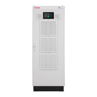
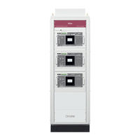
Circutor SVGm Instruction Manual (108 pages)
Static var generator
Brand:
Circutor
| Category:
Portable Generator
| Size: 20 MB
Table of Contents
Safety Precautions
3
Disclaimer
3
Table of Contents
4
Contents
4
Revision Log
6
Symbols
6
1�- Verification Upon Reception
7
1�1�- Reception Protocol
7
1�2�- Transport and Handling
7
1�3�- Storage
9
2�- Product Description
10
3�- Device Installation
14
3�1�- Preliminary Recommendations
14
3�2�- Installation Location
15
3�2�1�- Ventilation Requirements
15
3�3�- Storage for Long Periods
17
3�4�- Installation
17
3�4�1�- WALL-TYPE Svgm
17
3�4�2�- RACK-TYPE Svgm
18
3�4�3�- CABINET-TYPE Svgm
19
3�5�- Connection
20
3�6�- Device Terminals
22
3�6�1�- WALL-TYPE Svgm: Svgm-3WF-XXXM and Svgm-4WF-XXXM
22
3�6�2�- RACK-TYPE Svgm: Svgm-3WF-100R and Svgm-4WF-069R
24
3�6�3�- CABINET-TYPE Svgm
25
3�7�- Connection Diagrams
29
3�7�1�- 4-Wire Connection and Current Measurement on the Mains Side
29
3�7�2�- 4-Wire Connection and Current Measurement on the Load Side
30
3�7�3�- 3-Wire Connection and Current Measurement on the Mains Side
31
3�7�4�- 3-Wire Connection and Current Measurement on the Load Side
32
3�7�5�- 3-Wire Connection and 2 Current Transformers on the Mains Side
33
3�7�6�- 3-Wire Connection and 2 Current Transformers on the Load Side
34
3�8�- PARALLEL CONNECTION of 2 to 100 Svgm
35
3�8�1�- Connecting Individual Devices
36
3�8�2�- Connecting Cabinets
37
4�- Operation
38
4�1�- Operating Principle
38
4�2�- Medium Voltage
39
4�3�- Remote Control
40
4�4�- Time Programmer
40
4�5�- Self-Test
41
4�6�- Thermal Protection
41
4�7�- Display
42
4�7�1�- Upper Area
42
4�7�2�- Central Area
43
4�7�3�- Lower Area
43
5�- Start
44
6�- Display
45
6�1�- Main Screen
45
6�1�1� - Single or Master Device
45
6�1�2� - Slave Device
46
6�2�- Voltage, Current and Frequency
47
6�3�- Mains Power and Cos
47
6�4�- Load Power and Cos
48
6�5�- Mains Phasors
49
6�6�- Load Phasors
49
6�7�- Alarms
50
6�8�- Warnings
52
6�9�- Temperature
55
6�10�- Ethernet Communications
55
6�11�- Device Information
56
6�12�- Slave Device Status
57
7�- Configuration
58
7�1�- Language
59
7�2�- Device Specifications
59
7�3�- Installed Devices
60
7�4�- Operating Limits
61
7�5�- Cos
62
7�6�- Reactive Power Offset
63
7�7�- Transformer Configuration
64
7�8�- Medium Voltage
65
7�9�- Remote Control
66
7�10�- Remote Control (Communications)
67
7�11�- Time Programmer
68
7�12�- TIME PROGRAMMER: Cos
68
7�13�- Ethernet Communications
70
7�14�- Rs-485 Communications
70
7�15�- Date / Time
71
7�16�- Password
71
7�17�- Save Data
72
8�- Rs-485 Communications
73
8�1�- Connections
73
8�2�- Protocol
74
8�2�1�- Example of Modbus Query
74
8�2�2�- Modbus Map
74
9�- Ethernet Communications
78
9�1�- Connection
78
9�2�- Web Site
78
10�- Maintenance
80
10�1�- Standard Maintenance
80
10�2�- Cooling Fans
82
10�3�- CHANGE of COOLING FANS: Svgm of 20�7 and 30 Kvar
82
10�4�- CHANGE of COOLING FANS: Svgm of 41�4 and 60 Kvar
85
10�5�- CHANGE of COOLING FANS: Svgm Type RACK
88
10�6�- CHANGE of COOLING FANS: Svgm of 69 and 100 Kvar WALL
91
10�7�- CHANGE of COOLING FANS: CABINET TYPE Svgm
92
10�8�- MAINTENACE of SURGE PROTECTIVE DECIVES: Svgm-3WF-XXXC-690 and Svgm-4WF-XXXC-550
93
11�- Technical Features
94
12�- Technical Service
104
13�- Guarantee
104
14�- Ce Certificate
105
Advertisement
Advertisement
Related Products
Circutor SVGm-4WF-030M-400
Circutor SVGm-3WF-030M-480
Circutor SVGm Series
Circutor SVGm-4WF-100M-400
Circutor SVGm-3WF-100M-480
Circutor SVGm-3WF-100C-480
Circutor SVGm-3WF-100R-480
Circutor SVGm-4WF-100C-400
Circutor SVGm-4WF-060M-400
Circutor SVGm-4WF-200C-400
Circutor Categories
Measuring Instruments
Relays
Automobile Accessories
Battery Charger
Controller
More Circutor Manuals
Login
Sign In
OR
Sign in with Facebook
Sign in with Google
Upload manual
Upload from disk
Upload from URL