Sign In
Upload
Manuals
Brands
Circutor Manuals
Measuring Instruments
AR6
Circutor AR6 Manuals
Manuals and User Guides for Circutor AR6. We have
2
Circutor AR6 manuals available for free PDF download: User Manual, Instruction Manual
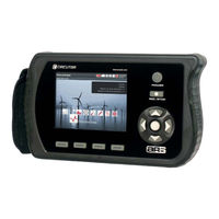
Circutor AR6 User Manual (71 pages)
Portable network analyzer
Brand:
Circutor
| Category:
Measuring Instruments
| Size: 7 MB
Table of Contents
Log of Revisions
2
Safety Instructions
3
Disclaimer
3
Recommendations before Using the Unit
3
Table of Contents
5
1 Verification Upon Reception
8
Components and Accessories
8
Storage
8
2 Description of the Unit
8
Introduction
8
Description
9
Active Menu
9
Active Measurement
9
Upper Icons
9
Configuration Summary
9
Date and Time
10
Power Button (On/Off)
10
REC/STOP Button (Log Control)
10
Validation (ENTER) Button
10
Navigation Keys
11
Buttons for Drop-Down Menus
11
Icons
11
Screen
11
Connectors
11
Voltage Inputs
11
Current Inputs
11
USB Port
11
Expansion Module
12
Auxiliary Power Supply
12
3 Instructions for Use
12
4 Technical Features
13
External Power Supply
13
Auxiliary Power Supply
13
Battery
13
Rechargeable Main Power Supply Battery
13
Clock Power Supply Internal Battery
13
Current Inputs
14
Current Clamps
14
Voltage Inputs
14
Unit Accuracy
15
Environmental Conditions
15
Mechanical Features
16
Screen
16
LCD Features
16
Memory
16
Log Capacity
17
Memory Errors
17
Icons and Symbols
18
5 Start-Up
18
Battery Installation
18
Power on
20
6 Drop-Down Menus and Keyboard
20
7 Main Menu
21
8 Settings Menu
22
Bios Configuration
22
Language
22
Time to Switch off Display
23
Contrast
23
Time to Lock Keyboard
23
Password
23
Phase Colours
23
Screen Background
23
Clock Setup
23
Decimals Setup
24
Usb Configuration
24
Safe Memory Access
24
9 System Information Menu
25
Update
25
Recover SD
25
Format SD with a PC Program
26
10 Measurement Manager Menu
26
Create
27
Modify
27
Transformer's Ratios
28
Measurement Configuration
29
Variable Selection
30
Events Setup (EVQ Setup)
31
Transients
32
Trigger Interval
33
Periodic Trigger
34
Photo Trigger Conditions Using Measured Data
34
Recording Trigger Conditions
35
Clear
35
Clear All
35
Remove
35
Activate
35
11 Measurement Analysis Menu
36
Records
36
Photos
37
Disturbances
38
Disturbance Wave Shape
38
RMS Value of a Transient or Event
39
Unipede Table
39
Events Grouping in Accordance with UNIPEDE Criteria
40
12 Waveform Menu
41
Photo
42
Pause
42
Run
42
Zoom In, Zoom out
42
13 Meter Menu
43
Real Time Rms Values Screen
43
VIEW Maximum or Minimum Values Option (Consumed or Generated)
44
Power Quality Screen
44
VIEW Quality Maximum or Minimum Values Option
44
Accumulated Energy Screen
45
Maximum Demand Screen
45
14 Phasors Menu
45
15 Quadrants Menu
46
16 Harmonics Menu
47
17 Connection Diagrams
49
Three-Phase Connection with Neutral
49
Three-Phase Aron Connection
49
Two-Phase Connection
50
Single-Phase Connection
50
Measured / Calculated Electrical Parameters in Accordance with the Connection Type
51
18 Screen Information
55
Upper Bar Icons
55
Battery Charge
56
Button Pad Lock
56
Phases Connection
56
Event Detection
57
Recording Status
57
Memory Capacity
57
USB Connection
57
Photo
57
Menu Tree
58
Switching off the Analyzer
59
19 Types of Files Generated
59
Rec.std Files
59
Pho.std File
64
Eqv.std File
64
Log.eva Files
65
Logs Location
66
File Downloading
66
20 Software Update
66
21 Power Vision Plus
66
22 Frequently Asked Questions
67
Can I Expand the Analyzer's Internal Memory
67
The Unit Is Not Responding to the Buttons . What Could be Happening and How Can Ifix It
67
What Does the Unit Log When It Takes Asnapshot
67
What Does It Log When It Captures the Wave Shape of an Event
67
What Software Is Used to Analyse the Logged Data
67
23 Maintenance and Technical Service
68
24 Guarantee
68
25 Ce Certification
69
Advertisement
Circutor AR6 Instruction Manual (62 pages)
PORTABLE NETWORK QUALITY ANALYZER
Brand:
Circutor
| Category:
Measuring Instruments
| Size: 5 MB
Table of Contents
Security Warnings
2
Liability Limitations
5
Recommendations Prior to Use
5
Table of Contents
6
1 General Overview
9
Initial Testing
9
Standard Components and Accessories
9
Icons and Symbols
9
2 Description of the Device
10
Introduction
10
Description
10
Active Measurement
11
Active Screen
11
Upper Icons
11
Configuration Summary
11
Time
11
On/Off
11
Recording
11
Confirmation
11
Navigation
11
Drop-Down Menus
11
Icons
12
Screen
12
Description of Connectors
12
Voltage Inputs
12
Current Inputs
12
USB Port
12
Expansión Module
12
Auxiliary Power Supply
13
3 Instructions for Use
13
4 Technical Specifications
13
External Power Supply
13
Power Supply of the Equipment
13
Battery
14
Rechargeable Main Power Supply Battery
14
Clock Power Supply Internal Battery
14
Current Input Specifications
14
Voltage Input Specifications
14
Voltage Inputs
14
Environmental Conditions
15
Mechanical Features
15
Screen
15
LCD Features
15
5 Start-Up
16
Battery Installation
16
Power on
17
6 Drop-Down Menus and Keyboard
17
7 Bios Configuration
18
Language
19
Sleep Delay
19
Lock Delay
19
Password
19
Zone
19
Screen Background
19
8 Main Menu
20
Measure Manager
21
Create
21
Modify
22
Delete
27
Disturbances
27
List of Disturbances
27
Harmonics
29
Phasors
31
Waveform
32
Zoom
33
Quadrants
33
Configuration
34
Clock Configuration
34
Decimals
35
System Information
35
Measure
36
RMS Screen
36
Instantaneous Screen
36
Maximum / Minimum Screen
37
Quality Screen
38
Instantaneous Screen
38
Maximums or Minimums Screen
39
Energy Screen
39
Maximum Demand Screen
39
9 Connection Diagrams
41
Three-Phase Connection with Neutral
41
Three-Phase Connection Without Neutral
41
ARON Three-Phase Connection
41
Two-Phase Connection
42
Single-Phase Connection
42
Electrical Parameters According to Connection
43
10 Screen Information
47
Upper Icons
47
Battery Charge
47
Keyboard Lock
48
Event Detection
48
Recording Status
48
Memory Capacity
48
USB Connection
48
Snapshot
48
Screen Diagrams
49
Menu Navigation
50
Switching off the Analyzer
50
11 Types of Files Generated
50
Trn
50
Std
51
Pho
54
Evq
55
Location of Recordings
55
File Downloading
55
12 Standards
56
Electrical Safety
56
Mechanical Protections
56
Electromagnetic Emissions
56
Electromagnetic Immunity
56
Quality Standards
56
13 Ce Certification
57
14 Upgrading
58
15 Calculation of Parameters
59
Calculation of Average Power According to the Number of Samples
59
Calculation of Apparent Power
59
Calculation of RMS Effective Voltage
59
Calculation of RMS Effective Current
59
Calculation of Base Apparent Power
59
Calculation of Base Power
59
Calculation of Reactive Power
59
Calculation of Power Factor
59
Calculation of Total Power
59
15.1.11 Calculation of Base Total Reactive Power
60
Calculation of Total Apparent Power
60
Vector Calculation of Total Apparent Power
60
Calculation of Total Base Apparent Power
60
15.1.15 Vector Calculation of Base Total Apparent Power
60
Calculation of Total Power Factor
60
Vector Calculation of Total Power Factor
60
Calculation of Total Power Factor Movement
60
Vector Calculation of Total Power Factor Movement
60
15.1.20 Calculation of Imbalance Coefficient
60
Calculation of Flicker Effect Perceptibility
61
15.1.23 Calculation of the K-Factor
61
Calculation of the Crest Factor
62
16 In Case of Malfunction
62
Advertisement
Related Products
Circutor AR5
Circutor AR5-L
Circutor AMk-ITF
Circutor AM2k-ITF
Circutor AFQm-3WF-100C-480
Circutor AFQm-4WF-060M-480
Circutor AFQm 100 A
Circutor AFQm-4WF-140C-550
Circutor airLINK
Circutor C-80
Circutor Categories
Measuring Instruments
Relays
Automobile Accessories
Battery Charger
Controller
More Circutor Manuals
Login
Sign In
OR
Sign in with Facebook
Sign in with Google
Upload manual
Upload from disk
Upload from URL