Sign In
Upload
Manuals
Brands
Chinook Manuals
Furnace
c120-2-d
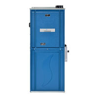
Chinook c120-2-d Manuals
Manuals and User Guides for Chinook c120-2-d. We have
1
Chinook c120-2-d manual available for free PDF download: Installation Manual And Owner's Manual
Chinook c120-2-d Installation Manual And Owner's Manual (57 pages)
Brand:
Chinook
| Category:
Furnace
| Size: 5 MB
Table of Contents
Table of Contents
2
1 Safety Regulation
6
Safety Labeling and Warning Signs
6
Important Information
6
Detection Systems
6
2 Introduction
8
Codes and Standards
8
Figure 1 Freeze Protection and Return Air Temp
8
1- Safety
9
2- General Installation
9
3- Combustion and Air Ventilation
9
4- Duct Systems
9
5- Acoustical Lining and Fibrous Glass Duct
9
6- Gas Piping and Pipe Pressure Testing
9
7- Electrical Connections
9
Electrostatic Discharge
9
Location
9
Table 1 Minimum Clearance to Combustible Material for All Units
9
1- Location Relative to Cooling Equipment
10
3 Venting
10
Figure 2 Installation in a Garage
10
Figure 3 Prohibited Installation
10
Figure 4 Dimensional Drawing
10
Table 2 Loose Parts List
10
4 Installation
11
General
11
Upflow Orientation
11
Figure 6 Drain Trap
11
Left Side Condensate Drain Connection
12
Right Side Condensate Drain Connection
12
Down Flow Orientation
12
Down Flow Condensate Drain Connection
12
Figure 7 Left Side Condensate Drain Connection
12
2- Downflow Venting Drainaged
13
3- Condensate Box Pressure Switch
13
Horizontal Right Orientation
13
Horizontal Right Condensate Drain Connection
13
Figure 8 : down Flow Orientation
13
Figure 9 Condensate Pressure Switch
13
2- Horizontal Right Vent Drainage
14
3- Condensate Box Pressure Switch
14
Horizontal Left Orientation
14
Horizontal Left Condensate Drain Connection
14
Figure 10 Horizontal Right Drain Trap Position
14
Figure 11 Horizontal Right Condensate Tubing
14
Figure 12 Pressure Switch Assembly
14
Condensate Box Pressure Switch
15
5 Duct Installation
15
Return Air Connections
15
1- Bottom Return Air Inlet
15
2- Side Return Air Inlet
15
Filter Arrangement
15
Supply Air Ducts
15
General Requirements
15
Figure 13 Horizontal Left Condensate Drain Connection
15
Figure 14 Return Air Base
15
1- Duct Work Acoustical Treatment
16
Table 3 Air Flow Capacity and Blower Data 2 Stage Variable
16
Table 4 : Air Flow Capacity and Blower Data 2 Stage Direct Drive
16
6 Gas Piping
17
Figure 15 Typical Gas Pipe Arrangement
17
Table 5 : Air Flow Capacity and Blower Date 1 Stage Direct Drive
17
Table 6 Maximum Capacity of Pipe in Ft³ of Gas/Hr
17
Table 7 Gas Pressure
17
Gas Pipe Grommet
18
7 Electrical Connections
18
Wiring
18
Table 8 Electrical Data
18
Wiring
19
Thermostats
19
Alternate Power Supply
19
Blower Speeds (4 Speed PSC Motor)
19
Figure 16 Power Cord Installation in the Furnace
19
Table 9 : Suggested Fan Speed on 1 Stage Furnace
19
Table 10 : Suggested Fan Speed on 2 Stage Furnace
19
Figure 17 Wiring Diagram - One Stage PSC
20
Figure 18 : Two Stage PSC - Furnace Control
21
Figure 19 : Two Stage ECM - Furnace Control
22
8 Venting
23
Special Venting Requirements for Installations in Canada
23
General
23
Figure 20 Electric Diagram X13
23
Materials
24
Direct Vent (2 Pipes Applications)
24
Non Direct Vent (1 Pipe) Applications
24
1- Termination Requirements for the Province of Alberta and Saskatchewan
24
Size of the Vent and Combustion Air Pipes
24
Connecting to Furnace
25
1- Combustion Air Piping
25
2- Exhaust Vent Piping
25
Figure 5 Vent Coupling and Adapter with Gaskets
25
Figure 21 Direct Venting
26
Figure 22 Multi Venting
26
Table 11 : Maximum Equivalent Straight Vent Length (Two Stage and Modulating)
27
Table 12 Maximum Equivalent Straight Vent Length (Single Stage)
27
Table 13 Deduction for Fitting
27
Table 14 Approved Combustion Air and Vent Pipe, Fitting and Cement Materials (U.S.A. Installation)
27
Combustion Air and Vent Piping Insulation Guidelines
28
Installing the Vent Termination
28
1- Concentric Vent
28
2- Two Pipes Termination
28
3- Sidewall Termination
29
9 Start Up, Adjustment and Safety Check
29
To Start the Furnace
29
Unit Operation Hazard
29
Setup Switches
29
Option Switches - 1 Stage, PSC and X13
29
Table 15: Option Switches Positions
29
1- Heat Mode
30
2- Cool Mode
30
3- Manual Fan on Mode
30
4- Twinning Interface
30
5- System Lockout and Diagnostic Features
30
6- System Lockout Features
30
7- Diagnostic Features
30
Option Switches - 2 Stage, PSC
30
1- Heat Mode
31
2- Cool Mode
31
3- Manual Fan on Mode
31
Table 16: Option Switches S1-3 & S1-4 Positions
31
Table 17: Option Switches S1-1 & S1-2 Positions
31
Table 18: Duty Cycles
31
Table 19: DIP Switches
32
Table 20: Duty Cycle
32
Table 21: DIP Switches
32
Fault Code Reset
32
Cool Mode
33
Table 22 : Dipswitch Setting for Airflow Selection
33
Prime Condensate Trap with Water
34
Check Safety Controls
35
Figure 23 Control Switch - Modulating Valve
35
Figure 24 Typical Flame Appearance
36
11 Maintenance of Your Furnace
36
Cleaning/Replacing the Filter
36
Advertisement
Advertisement
Related Products
Chinook c120-1-x
Chinook c120-1-d
Chinook c120-2-v
Chinook c105-1-x
Chinook c105-1-d
Chinook c105-2-d
Chinook c105-2-v
Chinook c45-1-x
Chinook c45-1-d
Chinook c75-1-x
Chinook Categories
Tent
Motorhomes
Air Compressor
Fan
Furnace
More Chinook Manuals
Login
Sign In
OR
Sign in with Facebook
Sign in with Google
Upload manual
Upload from disk
Upload from URL