Sign In
Upload
Manuals
Brands
Carrier Manuals
Air Conditioner
AirV 68RV11302A
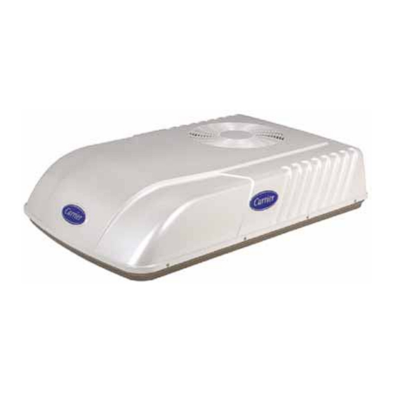
Carrier AirV 68RV11302A Manuals
Manuals and User Guides for Carrier AirV 68RV11302A. We have
2
Carrier AirV 68RV11302A manuals available for free PDF download: Service Manual
Carrier AirV 68RV11302A Service Manual (49 pages)
Brand:
Carrier
| Category:
Air Conditioner
| Size: 2.71 MB
Table of Contents
Service Manual
1
Table of Contents
6
Figure Number
10
Paragraph Number
10
Description
10
Introduction
10
Serial Number Identification
10
Design Change Descriptions
10
Figure 1-1 Model/Serial Number Plate (Typical)
10
Table 1-1 Model Chart
11
Figure 1-2 Roof Unit Component Identification
12
Table 1-2 Additional Support Manuals
12
Figure 1-3 Ceiling Unit Component Identification (Free-Blow)
13
Figure 1-4 Component Identification - Low Profile - Upper Unit
14
Figure 1-5 Component Listing-Ceiling Unit for Ducted Systems
15
Figure 1-6 Ducted System Air Flow Arrangement
16
Figure 1-7 Serial Number Locations
17
Airv SYSTEM COMPONENT SPECIFICATIONS
18
Refrigerant Charge
18
Compressor - 115 Volts, 60 Cycles, 1 Phase
18
Compressor - 220 Volts, 50 Cycles, 1 Phase
18
Thermostat Range (All Free Blow Units)
18
Start-Up
18
Refrigerant Cycle-Standard System
18
Figure 1-8 Refrigerant Flow Schematic (Standard System)
18
Refrigerant Cycle - Heat Pump
19
Cooling
19
Heating
20
Troubleshooting
21
No Power to Unit
21
Ducted Unit will Not Operate
21
Ducted Unit will Not Cool
21
Compressor Power Supply Open
21
Compressor Runs but Cycles, Fan Operating Erratically
21
Cycles on Compressor Overload
22
Insufficient Cooling, Cooling Air Not Adequate
22
Condenser Air Not Adequate
22
Insufficient Cooling
22
Compressor Flooding
22
Heater Cycles on Limit Switch (Heat/ Cool Version Only)
22
Air Sweep Not Working (Free Blow Version Only)
22
Water Leakage
22
Inadequate Heat (Free-Blow Heat Only)
23
Inadequate Heat (Heat-Pump)
23
Clearing Diagnostic Alarms
23
Table 2-1 System Self-Diagnostics Function (Ducted Remote)
24
Service and Maintenance
25
Preventative Maintenance
25
Service - General
25
Ceiling Unit - Free Blow Systems
25
Filter Removal
25
Ceiling Grill Removal
25
Ceiling Panel Removal
26
Master Control Switch
26
Air Sweep Switch Removal
26
Figure 3-2 Ceiling Grill - Free Blow
26
Figure 3-3 Ceiling Panel Assembly
26
Figure 3-4 Ceiling Panel with Heat Option
26
Figure 3-5 Control Box Assembly - Free Blow
26
Indoor Thermostat Removal
27
Air Sweep Removal
27
Heat Strip Assembly Removal
27
Figure 3-6 Indoor Thermostat
27
Figure 3-7 Air Sweep Motor
27
Figure 3-8 Heat Strip Assembly
27
Figure 3-9 Filter Removal - Ducted Unit
28
Figure 3-11 Control Box & PCB Cover
28
Figure 3-12 Control Box Assembly - Ducted
29
Figure 3-13 Main/Display Pcb's
29
Figure 3-16 Control Box Removal
30
Figure 3-17 Water Cover Removal
30
Compressor Replacement
30
Figure 3-18 Upper Scroll Assembly
31
Figure 3-19 Motor Assembly
31
Figure 3-20 Spring Clamp Removal
31
Figure 3-21 Motor Clip Removal
31
Figure 3-22 Condenser Fan Removal
32
Figure 3-23 Blower Wheel
32
Figure 3-24 Condenser with Motor Assembly & Compressor
32
Evaporator Blower Wheel Adjustment or Removal
32
Figure 3-25 Set-Up for Discharging a Capacitor
33
Capacitor Troubleshooting
33
Figure 3-26 Cover Assembly - Low Profile
34
Figure 3-27 Upper Scroll Assembly Locking Tabs (B.) & Screw Locations (C.)
34
Figure 3-28 Upper Scroll Assembly Keeper Tab Release
34
Service - Upper Unit - Low Profile
34
Figure 3-29 Upper Scroll & Control Box Cover Removed
35
Figure 3-30 Condenser Fan Assembly & Retaining Ring
35
Figure 3-31 Condenser Fan Motor & Fan Assembly Stop
35
Figure 3-32 Condenser Fan Motor & Fan Assembly Tab
35
Condenser Motor Removal
36
Figure 3-33 Condenser Motor Ground
36
Figure 3-34 Evaporator Motor Locking Tabs
36
Figure 3-35 Evaporator Motor/Blower Assembly in Cradle
36
Compressor Replacement
37
Figure 3-36 Evaporator Blower Wheel (Flush with End of Motor Shaft)
37
Figure 3-37 Control Box Assembly with Capacitor
37
Figure 3-38 Remote Control Components
38
Figure 3-39 Remote Control PCB (FR9 Location)
38
Thermostat Installation and Start-Up Instructions (Wall Mounted)
39
Check Thermostat Operation
40
Temperature Display
40
Timeguard Timer
41
Cycle Timer
41
Minimum on Timer
41
Error Messages
41
Figure 3-40 Wall Thermostat Wiring Diagram - Cool Only Model
41
Figure 3-41 Wall Thermostat Wiring Diagram - Heat/Cool Model
42
Wiring Schematics
43
Introduction
43
Figure 4-1 Upper Unit Schematic - Standard & HC
43
Figure 4-3 Ceiling Unit Schematic - Cooling Only
44
Advertisement
Carrier AirV 68RV11302A Service Manual (20 pages)
Rooftop Air Conditioning Systems
Brand:
Carrier
| Category:
Air Conditioner
| Size: 0.79 MB
Advertisement
Related Products
Carrier AirV 68RV15102A
Carrier AirV 68RV15103A
Carrier AirV 68RV14102A
Carrier AirV 68RV14103A
Carrier AirV 68RV14112A
Carrier AirV 68RV11112A
Carrier AirV 68RV11122A
Carrier AirV 68RV14113A
Carrier AirV 68RV14123A
Carrier AirV 68RV0010BA
Carrier Categories
Air Conditioner
Heat Pump
Furnace
Thermostat
Chiller
More Carrier Manuals
Login
Sign In
OR
Sign in with Facebook
Sign in with Google
Upload manual
Upload from disk
Upload from URL