Sign In
Upload
Manuals
Brands
Carrier Manuals
Chiller
30KAV-ZE 350A
Carrier 30KAV-ZE 350A Manuals
Manuals and User Guides for Carrier 30KAV-ZE 350A. We have
1
Carrier 30KAV-ZE 350A manual available for free PDF download: Installation, Operation And Maintenance Instructions
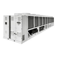
Carrier 30KAV-ZE 350A Installation, Operation And Maintenance Instructions (96 pages)
Liquid chiller with variable speed screw compressor and greenspeed smart technology
Brand:
Carrier
| Category:
Chiller
| Size: 11.35 MB
Table of Contents
Table of Contents
3
Safety Consideratons
5
Protection Devices Safety Considerations
5
Refrigerant Safety Considerations
7
Installation Safety Considerations
9
Maintenance Safety Considerations
10
Electrical Safety Considerations
10
System Interventions Safety Considerations
11
Receipt of Goods
12
Checking the Equipment Received
12
Handling
12
Positioning
13
Proximity to Walls
13
Underneath a Roof
13
Installation of Multiple Chillers
13
Positionning of Potentially Flammable Zone Around the Unit
14
Dimensions, Clearances
15
30KAV-ZE 350A & 400A; 30KAVIZE 500; Without Hydraulic Module
15
30KAV-ZE 350A & 400A, with Hydraulic Module
15
30KAV-ZE 450A & 500A, Without Hydraulic Module
16
30KAV-ZE 450A & 500A, with Hydraulic Module
16
30KAV-ZE 550A & 600A; 30KAV-ZE 350A, 400A, 450A, 500A - Opt 119; 30KAVPZE 350A, 400A, 450A, 500A; 30KAVIZE 800; Without Hydraulic Module
17
30KAV-ZE 550A & 600A; 30KAV-ZE 350A, 400A, 450A, 500A - Opt 119; 30KAVPZE 350A, 400A, 450A, 500A
17
With Hydraulic Module
17
30KAV-ZE 650A & 750A; 30KAV-ZE 550A - Opt 119; 30KAVPZE 550A; Without Hydraulic Module
18
30KAV-ZE 550A - Opt 119 & 30KAVPZE 550A; with Hydraulic Module
18
30KAV-ZE 800A; 30KAV-ZE 600A & 650A - Opt 119; 30KAVPZE 600A & 650A; Without Hydraulic Module
19
30KAV-ZE 600A - Opt 119; 30KAVPZE 600A; with Hydraulic Module
19
30KAV-ZE 750A & 800A - Opt 119; 30KAVPZE 750A & 800A
20
30Kav-Ze 900A; 30Kavize 1100; 30Kavize 1250
20
30Kav-Ze 1000A
21
30KAV-ZE 1100A; 30KAV-ZE 900A - Opt 119
21
30KAV-ZE 1200A & 1300A; 30KAV-ZE 1000A & 1100A - Opt 119
22
Water Connections
23
Operating Precautions
23
Victaulic Type Hydraulic Connections
24
Evaporator Water Boxes Screws Tightening
25
Flow Rate Detection
25
Frost Protection
25
Adjusting the Installation Nominal Water Flow Rate
26
Evaporator Water Flow Recirculation
27
Water Flow Evaporator Bypass
28
Variable Flow Evaporator
28
Minimum System Water Volume
28
Maximum System Water Volume (Option 293)
29
Minimum & Maximum Chilled Water Flow Rate
29
Evaporator Pressure Drop Curves
30
Electrical Connections
31
Power Supply
31
Voltage Phase Imbalance (%)
31
Power Connection/Disconnect Switch
31
Power Cable Access Routing
31
Recommended Cable Sections
32
Field-Installed Control Wiring
33
Customer and Service Power Reserves
33
Fan Motors
33
Speed Regulator
35
Cabinets for the Electrical Equipment
35
Electrical Data
36
Short Circuit Current Withstand Capability
39
Compressor Usage Per Circuit (A, B)
40
Electrical Data Notes
41
Major System Components
42
Compression Function
42
Evaporator Function
44
Economizer Function
44
Sensors
44
Condenser Function
44
Application Data
45
Unit Operating Range
45
Physical Data
46
System Inital Start-Up
50
Checks before System Start-Up
50
Commissioning
50
Essential Points to Check
51
Unit Start-Up Checklist for Installers Prior to Contacting Carrier Service
52
System Standard Maintenance
55
Level 1 Maintenance
55
Level 2 Maintenance
56
Level 3 (or Higher) Maintenance
57
Tightening Torques
57
Condenser Coils Maintenance
58
Flooded Evaporator Maintenance
59
Screw Compressor Maintenance
59
Variable Frequency Drive Maintenance
60
Precautions When Fitting the Casing Panel to the Side of the Control Cabinet
60
System Final Shutdown
61
Shutting down
61
Recommendations for Disassembly
61
Fluids to be Recovered for Treatment
61
Materials to be Recovered for Recycling
61
Waste Electrical and Electronic Equipment (WEEE)
61
Options
62
Hydraulic Module (Options 116A / 116W)
65
Free Cooling Dry Cooler (Option 313)
75
Brine (Options 5 / 6 / 8)
76
Heat Recovery (Options 49 / 50 / 50+)
82
Operation of Two Units as a Master/Slave Pair (Option 58)
88
Service Valves (Option 92)
88
Ultra Fast Capacity Recovery (Option 295+)
89
Connected Services (Option 298A)
90
Low & very Low Noise (Options 15 / 15LS)
92
VFD High Ambient (Option 16)
93
Appendices (Provided in the Document Wallet with the Instruction Manual)
95
Appendix 1: Declaration of Conformity
95
Appendix 2: Wiring Diagram
95
Appendix 3: Machine PID
95
Appendix 4: Dimensional Drawings
95
Advertisement
Advertisement
Related Products
Carrier AquaForce PUREtec 30KAV-ZE 350
Carrier AquaForce PUREtec 30KAV-ZE 400
Carrier AquaForce PUREtec 30KAV-ZE 500
Carrier AquaForce PUREtec 30KAV-ZE 900
Carrier AquaForce PUREtec 30KAV-ZE 1200
Carrier AquaForce PUREtec 30KAV-ZE 1300
Carrier 30KAV-ZE 750A
Carrier 30KAV-ZE 800A
Carrier 30KAV-ZE 900A
Carrier 30KAV-ZE 1000A
Carrier Categories
Air Conditioner
Heat Pump
Furnace
Thermostat
Chiller
More Carrier Manuals
Login
Sign In
OR
Sign in with Facebook
Sign in with Google
Upload manual
Upload from disk
Upload from URL