Sign In
Upload
Manuals
Brands
Carel Manuals
Heat Pump
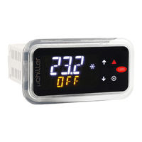
MuChiller UCHBE00001130
Carel MuChiller UCHBE00001130 Manuals
Manuals and User Guides for Carel MuChiller UCHBE00001130. We have
1
Carel MuChiller UCHBE00001130 manual available for free PDF download: User Manual
Carel MuChiller UCHBE00001130 User Manual (109 pages)
Controller for Chiller/Heat Pump
Brand:
Carel
| Category:
Heat Pump
| Size: 3 MB
Table of Contents
General Warnings
3
Key to the Symbols
4
Index
5
Introduction
7
Main Functions
7
Accessories
8
Models
8
User Terminal
8
EVD Evolution/Evd Evolution Twin Valve Driver
9
Pressure Sensors
9
Temperature Sensors
9
Ultracap Module
10
Unipolar Valve
10
USB/RS485 Converter
11
Panel Version
12
Warnings
12
Mountin
12
Installation
12
DIN Rail Version
13
Electrical Installation
13
Removal
13
Description of the Terminals
14
DIN Rail Model
14
Enhanced / High Efficiency
14
Panel Model
14
Probe Connection
15
0-10 VDC Probes
15
NTC Probes
15
4-20 Ma Probes
15
Connecting Serial Ports with Two Circuits
16
Positioning Inside the Panel
16
Connection to Power+
17
Positioning of Probes/Components
18
Water-Cooled Unit (Left) and Air-Cooled Unit (Right)
18
Functional Diagrams
19
Chillers, On/Off Compressors and Thermostatic Expansion Valve
19
Analogue Inputs - Master Circuit 1
20
Analogue Inputs - Slave Circuit 2
20
Digital Inputs - Master Circuit 1
20
Digital Inputs - Slave Circuit 2
20
Analogue Outputs - Master Circuit 1
21
Analogue Outputs - Slave Circuit 2
21
Digital Outputs - Master Circuit 1
21
Digital Outputs - Slave Circuit 2
21
Chillers, On/Off Compressors and Unipolar Exv Expansion Valve
28
Analogue Inputs
34
Analogue Outputs
34
Digital Inputs
34
Digital Outputs
34
APPLICA App
35
Commissioning
35
Configuration Procedure
35
Preparing for Operation
35
Unit Set-Up Parameter List
36
Applica: Date and Time Setting
37
Applica Desktop
38
Applica: Copy Configuration
38
Commissioning Software (Applica Desktop)
38
Icons
41
Keypad
41
User Interface
41
Standard Display
42
Dashboard
42
Direct Access Functions
43
Programming Menu
44
Programming Mode
44
Functions
46
PID Control
46
Temperature Control
46
Set Point Compensation
47
Request from BMS
48
Compensation in Heating
48
High Evaporator Outlet Temperature Alarm
48
Compensation in Cooling
48
User Pumps
49
Frost Protection Alarm
50
Frost Protection Control
50
Frost Protection Alarm Operation
51
Frost Protection Threshold with Glide
52
Capacity Distribution
53
Frost Prevention
53
Type of Rotation
53
Frost Protection with the Unit off
53
Capacity Distribution with BLDC Compressors
54
Compressor Capacity Distribution in Steps
54
Force Rotation (Destabilisation)
54
Rotation Due to Alarm
54
Predefined BLDC Compressors
55
Safety Times
55
Tandem BLDC Oil Equalisation
56
BLDC Compressor Protectors
56
BLDC Oil Recovery
56
BLDC Compressor Start-Up
56
BLDC Comp. Alarm Prevention
58
Prevention Actions for BLDC Compressors
58
High Compression Ratio Prevention (Zones 3-4)
59
Low Evaporation Pressure Prevention (Zone 2)
59
High Condensing Pressure Prevention (Zone 5)
60
High Evaporation Pressure Prevention (Zone 7)
60
High Motor Current Prevention (Zone 6)
60
Low Compression Ratio Prevention (Zone 8)
60
Compressor Alarms
61
Compressor Delay at Start-Up/In Operation
61
Compressor Shutdown
61
Power+ Speed Drive
61
Source Pump
62
Source Fans
62
Dedicated Electronic Expansion Valve Parameters
62
Control of the Expansion Valve
62
Control in Chiller Mode
63
Control in Heat Pump Mode
64
Set Point Control
64
"Low Noise” Function
65
Fan Anti-Blocking Function
65
Condensing Unit with Common Air Circuit
66
Free Cooling
66
Types of Free Cooling
66
Air-Cooled Condensing Unit with Separate Air Circuit
67
Outputs Used
67
To Enable Free Cooling
67
Water-Cooled Condensing Unit
68
Dynamic Control Gain
69
Free Cooling Functions
69
Valve Anti-Block Management
70
Effectiveness Control
70
End Defrost Can be Managed in Two Ways
71
Example of Defrost Activation
71
Defrost Procedure
71
Cycle Reversal and Waiting Time after Reversal
72
Decrease Capacity to Start Defrosting
72
Synchronisation
72
Waiting Time before Reversing the Cycle
72
Table of Contents
73
Waiting after Cycle Reversal (Case with Comp. ON)
73
Defrosting
73
Dripping (Case with Compressor On)
73
Decreased Compressor Capacity to End Defrost
73
Post-Dripping Phase (Case with Comp. OFF)
74
Quick Start Phase (Case with Comp. OFF)
74
Sliding Defrost
74
User Code Description Def Min Max UOM
74
Defrost Synchronisation
75
Independent
75
Simultaneous
75
Defrosting
75
User Code Description Def Min Max UOM
75
4-Way Valve Management
76
Manual Device Management
76
Parameter Table
77
Compressor
79
BLDC and Inverter
81
Valve
81
Source
82
BDLC Compressor Speed in Defrost 80.0 0.0
83
Dripping: Duration 90
83
Min
83
S S047 Defrost: Max Duration
83
S S050 Minimum Delay between Consecutive Defrosts
83
S S051 BDLC Compressor Speed in Defrost
83
S S046 Defrost: Min Duration
83
4-Way Valve: Pressure Differential for Reversing 3.0 0.0
84
I/O Settings
84
M S054 4-Way Valve: Pressure Differential for Reversing
84
BMS Port
86
Dashboard Values
86
Password
86
Settings
88
Coil Status
89
Supervisor Table
89
Input Status
90
Holding
92
Register
92
Input Register
96
Active Alarms
98
Alarms and Signals
98
Types of Alarms
98
Alarm List
99
Technical Specifications
102
Advertisement
Advertisement
Related Products
Carel MuChiller UCHBE00001140
Carel MuChiller UCHBP00000090
Carel MuChiller UCHBD00001130
Carel MuChiller UCHBP00000100
Carel MuChiller UCHBDH0001140
Carel MuChiller UCHBDE0001140
Carel uChiller UCHBE00001230
Carel uChiller UCHBE00001150
Carel uChiller UCHBD00001230
Carel uChiller UCHBD000X1230
Carel Categories
Controller
Humidifier
Control Unit
Touch terminals
Measuring Instruments
More Carel Manuals
Login
Sign In
OR
Sign in with Facebook
Sign in with Google
Upload manual
Upload from disk
Upload from URL