Sign In
Upload
Manuals
Brands
Camfil Manuals
Dust Collector
FARR GOLD GS48
Camfil FARR GOLD GS48 Manuals
Manuals and User Guides for Camfil FARR GOLD GS48. We have
1
Camfil FARR GOLD GS48 manual available for free PDF download: Installation, Operation And Maintenance Manual
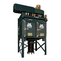
Camfil FARR GOLD GS48 Installation, Operation And Maintenance Manual (206 pages)
Brand:
Camfil
| Category:
Dust Collector
| Size: 10 MB
Table of Contents
Section 1
4
Table of Contents
4
Introduction
8
Section 100 - Safety Precautions
10
Understand Signal Words and Symbols
10
Warning Decals and Guards
10
Lock-Out / Tag-Out Requirements
11
Section 200 - Receiving Your Equipment
12
The Purchaser's Responsibility
12
System Components
12
Understanding Your Serial Plate
13
Un-Crating and Inspection
13
How Your Equipment Is Shipped
13
Section 300 - Installation of Your Equipment
14
Gold Series Assembly Tools
14
Section 310 - Assembling Your Farr Gold Series
15
Hardware
15
Hoppers
16
Support Legs and Braces
17
Hopper Support Legs and Braces
17
Filter Module
17
Channel Baffle Inlet
18
Discharge Assembly
20
Platform / Ladder
20
Collector Top Access Rails
22
Farr Gold Series Integrated Safety Monitoring Filter (Ismf)
22
Filter Installation / Replacement
23
Differential Pressure Monitor
23
Section 320 - Attaching Duct Work to Your Farr Gold Series
24
Inlet Duct Design (Side View)
24
Inlet Duct Design (Top View)
25
Inlet Flanges
26
Discharge Hopper Flange
30
Top Mount Fan Discharges
30
Remote Mount Fan Discharges
30
Section 330 - Field Utility Connections
31
Motor Connections
32
Timer Control
32
Solenoids
32
Solenoid Heaters
35
Collector Timer Control Connections
36
Integrated Safety Monitoring Filter - Ismf
36
Compressed Air Connection
37
Sprinkler Connections
38
Section 340 - Explosion Vents
40
Concerning Explosion Vents
40
General Explosion Vent Guidelines
41
Explosive Dusts
41
Explosion Vent Operation
42
Location of Vents and Vented Equipment
42
Ignition Sources
43
Vent Discharge Ducts
43
Vent Inspection and Maintenance
43
Section 350 - Filter Installation and Replacement
44
Clean Seal Filter Upgrade
45
Pre-Coating Procedure
46
Section 360 - Precoating of Filters
46
Section 370 - Glide Pack / Riga Flo SMF Installation
47
Transitioning: Top Mounting Arrangement
47
Remote Mounting Arrangement
47
Filter Assembly: Prefilter
47
Final Filter Holding Frame and Clips
47
Final Filter Assembly
47
Magnehelic Gage and Accessory Kit
47
Magnehelic Gage and Accessory Kit
48
Magna Pac / Hepa Filter SMF Installation: Transitioning
48
Final Filter
48
Filter Assembly: Prefilter
48
Section 380 - Overbag Assembly
49
Section 400 - Operation of Your Equipment
50
System Operation
50
Cleaning Filters
51
Cleaning Components: Header (Compressed Air Pressure Reservoir)
51
Solenoid/Diaphragm Valves
51
Pulsejet Blow Pipe
51
Features
53
Specifications
54
System Overview
55
Installing the Controls
56
Electrical Hookup
56
Dust Collector Controller Operation
57
Run Mode
57
Offline Cleaning Mode
57
Standby Mode
57
Program Mode
57
Solenoid Output
58
Programming the Core Timer Module
58
Alarm Events
58
Solenoid on Time
59
Number of Offline Cleaning Cycles
59
Offline Cleaning Time Delay
59
Standby
59
P Pressure Differential Meter Programming
59
Solenoid off Time
59
P Cleaning High Set Point
61
Security Code
61
P Cleaning Low Set Point
61
P Alarm High Set Point
61
P Unit of Measure
61
Zero Calibration
62
Core Expander Module Addressing
62
Communications Jumper Logic
62
Core Timer Module Status Leds
62
Expansion Module Leds
63
Dwyer DCT1000 Automatic Timer Controller Features
66
Integrated Control Panel
69
Rotary Air Lock
69
Fan Operation
70
Basic Cast Air Lock
70
Installation
70
Fabricated Air Lock
70
Startup Procedure
73
Shutdown Procedure
73
Recommended Timer Settings
74
Section 500 - Preventive Maintenance and Troubleshooting
75
Filter Elements
75
Hopper
75
Fan Motor Lubrication
75
Inspection Log
76
Automatic Timer Control (if Equipped)
76
Cleaning and Repair
76
Solenoid and Diaphragm Valves
76
Suggested Preventative Maintenance Schedule
77
High Pressure Drop
78
Moisture in Collector
79
Low Air Pressure
80
Controller Failure
80
Dust Bridging in Hopper
81
Media Failure
82
Poor Efficiency
83
Poor Airflow
84
Abnormal Noise
85
Repeat Fires or Explosions
86
Installation Problems
86
Section 600 - Definitions
88
Section 700 - Replacement Parts List
92
Section 800 - Job Specific Information
99
Section 2
134
Installation, Operation and Maintenance
135
Introduction
135
Prescribed Design Considerations
135
Lock out / Tag out
136
Safety Precautions
136
Installation
137
Performance Limits
137
Inspection and Maintenance Cover
139
Locking Mechanism (Patent Pending)
139
Operation and Maintenance
139
Flap Blade Replacement
140
Activation Sensor
141
Advantages
141
Sensor Specifications
141
Sensor Wiring
142
Post Activation Inspection
143
When an Explosion Activates Your Valve
143
Replacement / Spare Parts
145
Dimensions
146
Documentation Requirements
147
Inspection
147
Installation
147
Installation, Inspection and Maintenance of Explosion Control Systems
147
Mechanical and Electrical
147
System Acceptance
147
Activation Sensor Circuit
148
Corrosion
148
Grounding and Bonding
148
Inspection Points
148
Blade to Seat Gap
149
Blade Wear
149
Body Wear
149
Bolts
149
Dust Buildup
149
Latching Arm
149
Manufacturers Inspection Form for the Stinger Isolation Valve
150
Advertisement
Advertisement
Related Products
Camfil FARR GOLD GS4
Camfil FARR GOLD GS6
Camfil FARR GOLD GS16L
Camfil FARR GOLD GS16SQ
Camfil FARR GOLD GS20
Camfil FARR GOLD GS24
Camfil FARR GOLD GS32
Camfil FARR GOLD GS60
Camfil FARR GOLD GS84
Camfil FARR GOLD GS120
Camfil Categories
Air Cleaner
Dust Collector
Measuring Instruments
Water Filtration Systems
Fan
More Camfil Manuals
Login
Sign In
OR
Sign in with Facebook
Sign in with Google
Upload manual
Upload from disk
Upload from URL