Table of Contents
Advertisement
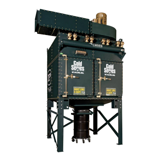
FARR GOLD SERIES
Customer
Western Technical College
LaCrosse, WI
Location
Job #
C44361005
AIR POLLUTION CONTROL
DUST COLLECTOR
®
I n s t a l l a t i o n , O p e r a t i o n a n d M a i n t e n a n c e M a n u a l
#C-1000-21 Rev. M-1 (US Customary Units)
Local Rep
Rep Phone
3505 S. Airport Road, Jonesboro, AR 72401 | 870-933-8048
www.camfilapc.com | e-mail: filterman@camfil.com | 800-479-6801
Synergic Engineering
Tim O'Keefe
952-906-3806
Camfil APC
Advertisement
Chapters
Table of Contents

Related Manuals for Camfil FARR GOLD GS2

Summary of Contents for Camfil FARR GOLD GS2
- Page 1 #C-1000-21 Rev. M-1 (US Customary Units) Customer Western Technical College Synergic Engineering Local Rep Tim O'Keefe LaCrosse, WI Location Rep Phone 952-906-3806 Job # C44361005 Camfil APC 3505 S. Airport Road, Jonesboro, AR 72401 | 870-933-8048 www.camfilapc.com | e-mail: filterman@camfil.com | 800-479-6801 AIR POLLUTION CONTROL...
- Page 2 Camtain™ GS2 on Pharmaceutical Dust GS6 on Silica Powder Multiple Gold Series on Soybean Seed Processing GS 8 on woodworking Multiple Farr Gold Series units on a mining rock crushing application.
- Page 3 GS48 on welding fume in Camfil APC’s own welding shop – Intake openings in the top of the duct every 20 feet facing upwards towards the ceiling actually use the ceiling as a capture plenum to help draw in the weld smoke. This is much more effective than facing the openings down.
-
Page 4: Table Of Contents
Table of Contents Introduction ............1 Section 100 —... - Page 5 Section 330 — Field Utility Connections ........24 330.1 —...
- Page 6 Section 400 — Operation of Your Equipment ....... 43 400.1 — System Operation ......... 43 400.2 —...
- Page 7 400.8 — Fan Operation ..........63 400.9 —...
-
Page 8: Introduction
DO NOT DISCARD THIS MANUAL! Congratulations on your selection of Camfil Air Pollution Control equipment. As the owner or operator of this equipment, you have an important responsibility to see that it is operated and maintained in It contains information a safe manner. - Page 9 WARNING! Do not attempt to operate or maintain this piece of equipment until you have read and thoroughly understood all of the safety information contained in this manual. All such information must be taken seriously. This piece of equipment contains moving parts and potential pinch points, which can cause serious injury or death.
-
Page 10: Section 100 - Safety Precautions
Camfil APC equipment is a part. It is the responsibility of the end user of this equipment to take the necessary precautions to minimize the inherent risks associated with combustible dust. -
Page 11: Lock-Out / Tag-Out Requirements
100.3 — Lock-Out / Tag-Out Requirements Control of this equipment must be in accordance with OSHA Standard 1910.147 “Control of Hazardous Energy (Lock-Out / Tag-Out)”. This standard “requires employers to establish a program and utilize procedures for affixing appropriate lock-out / tag-out devices to energy isolating devices and to otherwise disable machines or equipment to prevent unexpected energizing, start-up or release of stored energy in order to prevent injury to employees”. -
Page 12: Section 200 - Receiving Your Equipment
It is the purchaser’s responsibility to file shortage reports and damage claims with the carrier and your Camfil APC representative. The carrier is responsible for any damage to the equipment while it is in transit unless specific arrangements are made otherwise. -
Page 13: How Your Equipment Is Shipped
200.3 — How Your Equipment is Shipped It is Camfil APC’s goal to ship our products as economically and practically as possible. In order to save our customers shipping costs, it is our goal to load your collector on as few trucks as necessary. -
Page 14: Section 300 - Installation Of Your Equipment
Section 300 — Installation of Your Equipment 300.1 — Gold Series Assembly Tools The following items may be required to install your unit: Only trained, authorized personnel should be permitted to service or maintain electrical or safety components. It is the buyers and installers responsibility to ensure that all applicable electrical and safety codes are met. -
Page 15: Section 310 - Assembling Your Farr Gold Series
Section 310 — Assembling Your Farr Gold Series 310.1 — Hardware Refer to Figure 3.11.1 for typical assembly points of a standard collector. Refer to the General Dimension drawings for specifics, such as item part numbers, inlet and outlet locations, foundation dimensions and accessories. -
Page 16: Hoppers
310.2 — Hoppers Locate the hoppers and support legs. Remove the hoppers from the skids and place on a flat, level surface. If your collector includes multiple hoppers place them in the correct configuration as shown on the General Dimensions drawing. Using a tape measure or string line, square the hoppers as necessary. -
Page 17: Support Legs And Braces
310.3 — Support Legs and Braces Refer to Figure 310.2.1 for general assembly and your support structure drawing for specific parts. Locate the support legs and bolt them to the corner support brackets. Locate the cross braces and bolt them to the support legs. If your collector contains knee braces, bolt one end to the support leg and the other end to the corner support bracket. -
Page 18: Channel Baffle Inlet
310.5.2 — Channel Baffle Inlet If your filter module is supplied with a lowered channel baffle assembly for the inlet, install at this time as follows: 1. Channel baffle tabs fit to the inside of the frame as shown. 2. Attach center baffle channel if required (Figure 310.5.2.2). 3. - Page 19 Figure 310.5.2.2 Refer to the Installation DVD for detailed procedures for installation.
-
Page 20: Discharge Assembly
310.6 — Discharge Assembly Figure 310.6.1 Locate the hopper discharge accessory supplied with Slide Gate your collector. This will be a drum kit/slide gate, rotary airlock or screw conveyor. Install the accessory to the Hose Clamp hopper discharge flanges using the General Dimensions drawing and Section 320 as a guide. - Page 21 Figure 310.7.1 Parts / Descriptions 1. Modular Platform for Ladder 2. Hand Rail Ass’y, Side 3. Hand Rail Ass’y, Front 4. Hand Rail Ass’y, Side, Ladder 5. Knee Brace Bracket, L.H. 6. Knee Brace Bracket, R.H. 7. Right Arm 8. Left Arm...
-
Page 22: Collector Top Access Rails
The GS Integrated HEPA Filter is used down stream from a Farr Gold Series Dust Collector to provide high efficiency filtration in applications requiring air recirculation. It contains a Camfil APC XH HEPA Filter that is 99.97% efficient on 0.3 μm Particles. The filter is housed in a Farr Gold Series frame which bolts directly to the roof of your FGS Collector. -
Page 23: Filter Installation / Replacement
Substituting filters other than original OEM filters would violate the NFPA standards and void the performance based certification of this filter system. Reference Camfil APC’s bulletin for the iSMF for more detailed information. 310.9.3 — Differential Pressure Monitor A Magnehelic Pressure Monitor must be installed to monitor the differential pressure across the filters. -
Page 24: Section 320 - Attaching Duct Work To Your Farr Gold Series
Section 320 — Attaching Duct Work to Your Farr Gold Series 320.1.1 — Inlet Duct Design (Side View) This section covers flange details and design guidelines for ducting to your Farr Gold Series dust collector. When you run ducting to your collector, it is important to follow these guidelines. 1. -
Page 25: Inlet Duct Design (Top View)
320.1.2 — Inlet Duct Design (Top View) In Figure 320.1.2.1 the Recommended design shows a straight section of duct that is at least 2 duct diameters long, before entering the inlet. The air direction will cause the dust to be evenly distributed to all of the filters in the collector. -
Page 26: Inlet Flanges
320.2 — Inlet Flanges Depending on the size and orientation of your Farr Gold Series collector, the inlet will have one or more of three inlet designs. These inlets are configured and classified with the number of modules that the collector uses to support the inlet plenum. Larger collectors may have more than one inlet plenum and vary in the size of the inlet. - Page 27 Units are inches; bolt holes are ”-16 NC Figure 320.2.2 Single Inlet Flange Drop-Out Module Double Inlet Flange Drop-Out Module Triple Inlet Flange Drop-Out Module...
- Page 28 Figure 320.2.3 Units are inches; bolt holes are ”-16 NC Side Outlet Flange Side Outlet Panel (Half) Top Outlet Flange Top Outlet Flange (Half)
- Page 29 Units are inches; bolt holes are ”-16 NC Figure 320.2.4 Top Outlet Double Top Outlet Triple...
-
Page 30: Remote Mount Fan Discharges
320.4 — Top Mount Fan Discharges Top mount fans, provided by Camfil APC, are field mounted on the top of the Farr Gold Series collector. All Camfil APC provided fans will have a fan damper supplied with the fan. When attaching duct work to this flange, always be sure to caulk or place gasket between the duct and damper outlet before bolting them together. -
Page 31: Section 330 - Field Utility Connections
Section 330 — Field Utility Connections Figure 330.1... -
Page 32: Motor Connections
330.1 — Motor Connections Follow all Lock-out/ Camfil APC can supply the fan, motor starter, and rotary air locks (or other discharge devices) Tag-out procedures for our dust collectors. However, the customer or Camfil APC representative may elect to supply before you make the fan and other accessories. - Page 33 Figure 330.3.1 Attach common wire to either end of the pre-wired common terminals Attach numbered hot (load) wired from controller to corresponding solenoid Table 330.3.2 Farr Gold Series Timer Requirements # of Timer Outputs # of Solenoids Double Timer Model / Diaphragms Outputs Dwyer...
- Page 34 Figure 330.3.3...
-
Page 35: Solenoid Heaters
Failure to do so can result in property The heater can be wired to the 110V power supply for the standard Camfil APC FDC controller, but it damage, personal must not be wired from the timer board. (The heater is rated at 100 watts.) injury, or death. -
Page 36: Collector Timer Control Connections
In like manner, the polyline fittings on the bottom of the Collector Timer Control provided by Camfil APC are labeled in the same manner. Simply connect the “Dirty Air / High Pressure” and the “Clean Air / Low Pressure ports on the collector to the same ports on the Timer Control, using matching polylines. -
Page 37: Compressed Air Connection
Collector & all located close to the unit. Camfil APC recommends that the compressed air supply be kept at iSMF Assembly. a dew point of -40 F. Make provisions for draining any condensation from the air reservoir with an automatic tank drain or by other means. -
Page 38: Sprinkler Connections
330.7 — Sprinkler Connections NOTE If your collector is equipped with a sprinkler system, locate the sprinkler connection coupling(s). If you are supplying Refer to the General Dimensions drawing for locations. more than one sprinkler connection Figure 330.7.1 shows a side wall sprinkler head system. A single 1/2” orifice sprinkler head is coupling with a installed into a GS sprinkler flange. - Page 39 Figure 330.7.3 shows an internal sprinkler system, which is used on large GS collectors. All sprinkler heads are supplied through a single coupling, welded near the bottom of a lower side panel. NOTE Water leaks in the collector will cause cartridge failure and hopper flow problems.
-
Page 40: Section 340 - Explosion Vents
Agency (NFPA) provides comprehensive guidelines for dealing with explosive dusts. Following is a list of publications that are highly recommended by Camfil APC for use in determining if the installation of your dust collection system meets all of the NFPA recommendations with regards to conveying, collecting and processing explosive dusts. -
Page 41: General Explosion Vent Guidelines
340.2 — General Explosion Vent Guidelines • It is important to note that venting does not prevent a deflagration. Venting can, however, minimize the destructive effects of a deflagration. • Refer to NFPA 654 Standard for design requirements for the complete dust collection system. •... -
Page 42: Explosion Vent Operation
• Appropriate signs should be posted to provide warning as to the location of a vent. Replacement decals are available from Camfil APC and are listed in the spare parts section of this manual. • A vent closure should be inspected and properly maintained in order to ensure dependable operation. -
Page 43: Ignition Sources
340.8 — Vent Inspection and Maintenance • Camfil APC incorporates rupture diaphragm style explosion vents on their dust collectors. Explosion vents should be inspected every three months. The inspection and maintenance points are outlined below. -
Page 44: Section 350 - Filter Installation And Replacement
To reach the inside cartridges Camfil APC provides a telescoping extraction pole with a hook on the end. 5. Remove a new cartridge from the shipping carton, taking care not to cut or otherwise damage the filter media. -
Page 45: Clean Seal Filter Upgrade
Figure 350.0.2 (left) Figure 350.0.3 (right) Filter extraction with hook on top of pan for Filter extraction with hook in hand hole on obsolete round gasket filters. bottom of the ban for new square gasket filters. Figure 350.0.4 350.1 — Clean Seal Filter Upgrade The enhanced Gold Cone top pan features gaskets placed at the edge of the pan to prevent dust from accumulating on the top. -
Page 46: Section 360 - Precoating Of Filters
Section 360 — Precoating of Filters In applications where the dust concentration is high and/or the dust particles are large (more than 0.5 μm), pre-coating of the filters is not required. In applications where the dust concentration is low and/or the dust particles are small (less than 0.5 μm), pre-coating will result in a higher initial efficiency and extended filter life. -
Page 47: Section 370 - Glide Pack / Riga Flo Smf Installation
Section 370 — Glide Pack / Riga Flo SMF Installation Figure 370.3.1.1 370.1 — Transitioning: Top Mounting Arrangement If a small unit (up to 1 high × 3 wide), a transition plate and air diffuser are supplied on the air entering side of the filter housing. Typically this plate is supplied with the cutout to match the blower or silencer opening with bolts attached. -
Page 48: Magna Pac / Hepa Filter Smf Installation: Transitioning
370.4.1 — Magna Pac / Hepa Filter SMF Installation: Transitioning Applies same as the Glide Pac / Riga Flo SMF. Insure all flange joints are sealed with either rope caulk or silicone. 370.4.2 — Filter Assembly: Prefilter Figure 370.4.2.1 This filter should be installed in the 2” wide track on the air entering or upstream side of the housing. -
Page 49: Section 380 - Overbag Assembly
Section 380 — Overbag Assembly If your application requires cartridge overbags your initial set of filters with your collector will already have these installed. This instruction is for replacement cartridges. If your filters require precoating, do this operation before assembly your new overbags. This operation is much easier with two people performing the assembly. -
Page 50: Section 400 - Operation Of Your Equipment
Section 400 — Operation of Your Equipment Camfil APC has prepared this proprietary user’s manual for the exclusive use of its customers. The recommendations contained herein are based on proven techniques and on test data believed to be reliable. It is intended that personnel having specialized training in accordance with currently accepted practice and normal operating conditions use this manual. -
Page 51: Cleaning Filters
400.2 — Cleaning Filters Figure 400.2.1 The Gold Cone cartridge elements are sequentially cleaned by back flushing with air. This momentary airflow reversal is induced by a short burst of compressed air. The air is released from the compressed air reservoir by a fast-acting, high-flow diaphragm valve. This “pulse” of air dislodges the accumulated dust from the filter element. - Page 52 Section 400.4 — FDC Controller Figure 370.4 Scan to see Farr Gold Series Instruction Video FDC Controller, Part 1...
-
Page 53: Features
Simple programming via push button and dial knob • Non-volatile memory for program and status storage • On-Demand operation with Camfil APC Differential Pressure Meter • 3-digit, 7-segment alpha-numeric Display • Settable alarm output relay normally open or normally closed on timer module •... -
Page 54: Specifications
400.4.2 — Specifications WARRANTY Inputs All of Camfil APC Supply 100–240 VAC, 50 / 60Hz, 4 VA max @ 240 VAC without loads Dust Collector Fuse 3A fast, 5x20 mm Controller products ∆ Pressure Switch Input Dry contact, 4 mA @ 13 VDC max... -
Page 55: System Overview
The Camfil APC Dust Collector Controller’s flexible design allows it to be adapted to many dust damage. In order to collector configurations. The Core Timer Control Module will sequentially pulse up to ten outputs keep abreast with in “On-Demand”... -
Page 56: Installing The Controls
50/60 Hz to the Controller, and the supplied voltage will be correspondingly switched to the outputs. 400.4.4 — Installing the Controls The Camfil APC Dust Collector Controller is designed to be mounted in most industrial environments. Its NEMA 4X enclosure also allows it to be mounted outdoors as well as in dusty environments. -
Page 57: Dust Collector Controller Operation
400.4.6.1 — Dust Collector Controller Operation The Camfil APC Dust Collector Controller is shipped from the factory with the default program (see details below). Power must be applied and solenoid(s) connected, in order to have a functioning system. From this point, Program Items can be tailored to the specific application. There are four basic modes of operation for the Controller;... -
Page 58: Alarm Events
400.4.7 — Alarm Events Alarm events are generated either by faulty solenoid detection or by High ∆P alarm detection. When a Solenoid Fault occurs, the Alarm Relay located on the Core Timer module changes state and the “System Status Alarm” LED turns on. To acknowledge the alarm and view its corresponding information, press the “Program Select”... -
Page 59: Solenoid On Time
400.1.8.3 — Solenoid On Time Default: 150 ms Select the “Solenoid On Time” Program Item as described above. This value sets the ON duration of the solenoid, and is adjustable from 0.10 to 0.50 seconds. 400.1.8.4 — Solenoid Off Time Default: 15 seconds Select the “Solenoid Off Time”... - Page 60 F ig u r e 1 – P r e s s u r e D iffe r e n tia l M e te r P r o g r a m m in g Normal Operation Figure 400.4.9 PRESSURE Change DIFFERENTIAL METER...
-
Page 61: P Alarm High Set Point
If the number is entered correctly, the programming sequence will continue. If the number is entered incorrectly, the display will revert to normal operation. If the security code is forgotten, Camfil APC Customer Service must be contacted for an emergency security code. -
Page 62: Zero Calibration
400.4.9.7 — Zero Calibration To calibrate the Pressure Differential Pressure meter, advance the programming until the display flashes set. With the system shut down (Blower stopped) press and hold the Up and the Down arrow buttons simultaneously until display stops flashing. Press the set button one time to exit programming and check to see if the meter is reading “00.0”. -
Page 63: Expansion Module Leds
Output Status The Output Status LED will light Green whenever the outputs on the Controller or expansion board are scheduled to fire. In case of an output related alarm (overcurrent, etc), the LED will turn Red until the Alarm is cleared or the outputs are no longer in queue. CANbus Status The CANbus Status LED will light whenever the unit is transmitting. - Page 64 Figure 400.4.10.2 Pressure Differential Meter Wiring...
- Page 65 Figure 400.4.10.3 Figure 400.4.10.4...
-
Page 66: Dwyer Dct1000 Automatic Timer Controller Features
400.5 — Dwyer DCT1000 Automatic Timer Controller Features The DCT1000 is designed for on-demand or continuous cleaning applications. Continuous cleaning applications do not require external inputs and can be used for time based “on demand” cleaning through use of the cycle delay feature. For on-demand applications, the plug-in pressure module can be used to take full advantage of all the DCT1000 features. - Page 67 This value should only be used on light loadings and is not recommended for fibrous dusts. The upper settable value is the calibration pressure of the pressure module and the lower limit is zero. Figure 400.5.1 Pressing Select will change the system to the High Alarm Setup Mode. NEMA 4X Enclosure High Alarm Setup...
- Page 68 Figure 400.5.2 Dwyer DCT1000 Timer Plug-in Pressure Module Wiring Diagram High Com Low Alarm Man DT Alarm 3 Position Selector Limit Limit Com Mode Ovr Cln Reset Com Switch 4-20 MA Output Process (IN H Last Output Time Off (sec) Time On (msec) High Limit Continuous...
-
Page 69: Integrated Control Panel
Camfil APC Customer Service at 1-800-479-6801 for a replacement packet. Unless a special RAL has been ordered for your system, Camfil APC supplies two standard types of airlocks, with many options available, please contact your sales representative for further information. -
Page 70: Basic Cast Air Lock
Consult the information packet attached to your fan before proceeding with installation and wiring. connections. (See If your fan does not include an information packet contact the fan supplier. If Camfil APC supplied Section 100.3) your fan, contact Camfil APC Customer Service at (1-800-479-6801). - Page 71 60 HZ Fan Performance Table Camfil APC Fan Sizes Static Pressure (in wg) vs Air Flow (cfm) Part # Model 208188-001 126GI-1.0-60-8 — 1320 1173 — — — — 208189-001 146GI-1.5-60-10 — — — — — — 1367 1228 1069 208181-001 15PLR-2.0-60-9...
- Page 72 50 HZ Fan Performance Table Camfil APC Fan Sizes Static Pressure (in wg) vs Air Flow (cfm) Part # Model FS1-50 209217-001 146CGI-1.0-50-9 1564 1408 1251 1095 — — — — — FS2-50 209218-001 PB1706-1.5-50-9.5 — — — — 1525...
-
Page 73: Startup Procedure
400.9 — Startup Procedure 1. Make a routine check of the fan, discharge devices, ductwork, electrical wiring, cartridges (clamped in position) and compressed air connections. 2. Make sure the collector doors are closed and latched and the slide gate is in the open position. 3. -
Page 74: Recommended Timer Settings
4. Repeat steps 2 and 3 until the dust collector stabilizes at 2 to 3 in w.g. These adjustments may have to be reversed as the filters age. Recommended Settings Pulse Duration (on time) 150 milliseconds This is Camfil APC’s recommended setting. Increasing this value will decrease compressed air consumption. Decreasing this value will increase compressed air consumption. -
Page 75: Section 500 - Preventive Maintenance And Troubleshooting
Farr Gold Series dust collectors may vary. Camfil APC often provides the fan with the collector, but many times the fan is provided by other sources. If Camfil APC provided the fan, it will be one of two types. One type has sealed-for-life bearings and requires no maintenance. The other type motor provided with the fan has grease fittings on the top and bottom of the motor. -
Page 76: Solenoid And Diaphragm Valves
An inspection log should be maintained to assure that a proper maintenance routine is followed. The following page is an example of a commonly used inspection log. Copy and use this inspection log or contact Camfil APC, Customer Service Department (1-800-479-6801) for a copy. -
Page 77: Suggested Preventative Maintenance Schedule
500.8 — Suggested Preventative Maintenance Schedule Date Time Inspector Notes DAILY 1. Record Differential Pressure (DP) “w.g. “w.g. “w.g. “w.g. “w.g. Check Controller & Pressure Drop 2. Are any Control indicators alarms on? Y / N Y / N Y / N Y / N Y / N 1. -
Page 78: High Pressure Drop
• Perform off-line cleaning • Add more compartments or modules and filter media • Evaluate dust to find correct Air-to-Cloth Ratio (Camfil APC lab) • Replace cartridges (service life is determined by the application) End of Cartridge service life •... -
Page 79: Moisture In Collector
(high air to cloth ratio) Collector undersized Install overbags to prevent blinding Perform off-line cleaning Add more compartments, modules or filter media Evaluate dust to find correct air to cloth ratio (Camfil APC lab) 510.2 — Moisture In Collector Cause Solution... -
Page 80: Low Air Pressure
• Keep fan running for 5 to 10 minutes after process is shut down • Insulate the collector if it is to be located outside System is not purged • Install a bypass line to allow pre-heating of the collection system after shutdown •... -
Page 81: Dust Bridging In Hopper
• Check to see if timer is indexing to all contacts • Check output on all terminals • Check wiring between controller and solenoid valves (repair) Improper wiring • Check power connections to board (correct if necessary) • Confirm the type of controller used and refer to appropriate section in this manual or the controller manual •... -
Page 82: Media Failure
• See sections following Moisture in Collector • Assure that only dry compressed is used, install air dryer • Insulate collector if it is located outside • Preheat the collector before operation • Purge the collector of all high humidity process air after operation Moisture in collector •... -
Page 83: Poor Efficiency
• Replace baffle plate with abrasion resistant material • Reduce velocity of inlet air, damper fan • Install filter cartridges of different media type Application too abrasive • Install additional modules to reduce Air-to-Cloth ratio • Confirm appropriate location of pickup points and hoods •... -
Page 84: Poor Airflow
• Confirm correct placement of cartridges, prevent ramping of filters • Confirm locking mechanism is in the closed position Leaking gaskets • Remove filters and clean tube sheet to assure a good seal • If cam-bars are not bent, replace support brackets for cam-bars •... -
Page 85: Abnormal Noise
510.9 — Abnormal Noise Cause Solution • Most Camfil APC provided fans range from 89 to 99 decibels • To reduce sound levels, install a fan silencer - Call Customer Service for a Quote. Normal noise level of fan •... -
Page 86: Repeat Fires Or Explosions
Cause Solution • Consult Camfil APC and install the required life safety measures as prescribed Dust is explosive in NFPA 654: Standard for the Prevention of Fire and Dust Explosions from the Manufacturing, Processing, and Handling of Combustible Particulate Solids. - Page 87 Wrong top panel, replace panel (if Camfil APC provided fan) Fan flange does not match top • Drill or cut flange into blank top panel (if other than Camfil APC fan) panel bolt pattern (top mount • Use alignment pins to match flanges during assembly fans only) •...
-
Page 88: Section 600 - Definitions
Section 600 — Definitions Abrasion Resistance The ability of a fiber or fabric (media) to withstand surface wears. ACFM Actual cubic feet of gas per minute. The volume of gas flowing per minute at the operating temperature, pressure, elevation and composition. Air-to-Cloth Ratio The ratio between ACFM flowing through a dust collector and the square feet of filter area available (ACFM/Ft2). - Page 89 Dust Cake A dust build-up on the filter elements that increases the efficiency of the filter media. Dust Loading The weight of solid particulate suspended in an air stream, usually expressed in grains per cubic foot (or grams per cubic meter). Electrostatic Forces The presence of an electrostatic charge on the particles and the filter can increase dust capture.
- Page 90 Magnehelic Gage An instrument used to measure differential pressure drop. Manometer A U-shaped tube filled with a specific liquid. The difference in height between the liquid in each leg of the tube gives the difference in pressure on each leg of the tube. Used to monitor differential pressure.
- Page 91 Pulse Clean Dust Collector A dust collector using short intermittent pulses of compressed dry air to clean dust from the filter media. Re-entrainment The phenomenon where dust is collected from an air stream and is then returned to the air stream. This occurs when dust is dislodged from a filter media during cleaning and is again captured by the same or an adjacent filter media.
-
Page 92: Section 700 - Replacement Parts List
If this information is not gasket geometry of available to you, please contact your Camfil APC Representative or Camfil APC Customer Service all of its filters to a at 1-800-479-6801 for genuine Camfil APC replacement parts. - Page 93 211922-011 TK-SY-244-34"L 211872-011 TK-XS - eXtreme Synthetic TK-XS-197-27"L 211922-012 TK-XS-244-34"L 211872-012 Other Items Camfil APC Part # Description Filter Accessories 084404-000 Pamic Filter 208721-001 Cartridge Removal Tool 203774-001 Pre-Coat, Dust, Expanded Perlite 20 lb. bag 207087-001 Overbag, Nylon, for Gold Cone Cartridge...
- Page 94 After Filter Fasteners 114353-000 C-99 Spring Fastener (for Riga-Flo 200 Filters) 063159-002 Swing Bolt (for Absolute 2000 HEPA Filters) 043911-002 Wing Nut (for Absolute 2000 HEPA Filters) 063343-000 Clamp (for Absolute 2000 HEPA Filters) After Filter Gage & Pneumatics 033988-003 Magahelic Gage, 0-4"...
- Page 95 Dust Collector Controller 214538-001 Basic Dust Collector Controller (BDC10) w/o Gage 214538-002 Basic Dust Collector Controller (BDC20) w/o Gage 214538-010 Camfil APC Dust Collector Controller Kit (FDC10) 214538-020 Camfil APC Dust Collector Controller Kit (FDC20) 214382-001 DFA-T2610-010 Timer Board 214383-001...
- Page 96 205764001 Door Hinge 205229001 Gold Bolt (price each, minimum of 100 per order) 074492000 Rope Caulk 251159001 Camfil APC Green - Touch-up Paint (1 GALLON) Safety Decals 205821001 Label, Entrapment 6"×3" 205822001 Label, Explosion 6"×3" 205819001 Label, Safety Instructions 3"×6"...
- Page 97 The following is a part list and diagram of common hardware parts on your collector. To identify your replacement part, match the item in the list with the balloon number on the diagram. Check the description to be sure you have the specific part for your collector. Item Part # Description...
- Page 98 206019-002 Manual Slide Gate 069441-015 Flex Hose - 10” Diameter 207551-007 Hose Clamp - 10” Diameter 209573-010 Drum Cover with Gasket 210511-001 Drum Latch ring 094562-001 55 Gallon Drum Fan (Refer to your fan name plate, bill of lading, or original packing slip for part no.) 210274-001 Differential Pressure Filter Kit...
-
Page 99: Section 800 - Job Specific Information
Section 800 - Job Specific Information 810 Sales order specific certified drawings 810.1 Top level print 810.2 Startup box print 810.3 Support drawing 810.4 810.5 810.6 820 Blower data 820.1 Fan curve and data sheets 820.2 Fan manual 830 Collector Discharge information 830.1 Airlock –... - Page 100 Reference drawing in startup box for latest Rev.
- Page 101 Reference drawing in startup box for latest Rev.
- Page 102 Reference drawing in startup box for latest Rev.
- Page 103 Fan-to-Size Project: Fan Selection Data Location: Contact: Fan Tagging: Camfil APC Fan Design Backward Inclined Class IV Product: Arrangement: SWSI Size/Model: Drive type: Direct Wheel Type: Acoustafoil AMCA Performance Class: Wheel Material: Mild Steel Wheel Width: 87.0 % Wheel Diameter: 100.0 %...
- Page 104 New York Blower Company Date: 1/7/2015 File: 2014-09440 Control: Sequence: Chg Order: Revision: Processor: CAMFIL APC Customer: Office Reference: 39700 Tagging: P/N 2262430019007 SO #C44361 FAN INFORMATION Quantity: Product Line: Backward Inclined SWSI Class IV Size: Bearing Mfg. & Model:...
- Page 105 Performance Curve Date: 06-Jan-15 File: 2014-09440-001 Performance Cust. No.: 288935 Options: Customer: CAMFIL APC Inlet Box 3505 S. Airport Road 87.0% Width Wheel Product Line: Backward Inclined SWSI Class IV - ACF Size: Capacity: Operating Volume (CFM): 11,500 Pressure (in wg): 15...
- Page 117 INSTALLATION MAINTENANCE, IM-100 OPERATING INSTRUCTIONS CENTRIFUGAL FANS AcF/PLR, AF, RTS, HPBC SOUND Some fans can generate sound that could be hazardous to exposed personnel. It is the responsibility of the system designer and user to determine sound levels of the system, the degree of personnel exposure, and to comply with applicable safety requirements to protect personnel from excessive noise.
- Page 118 HANDLING AND STORAGE Fans should be lifted by the base, mounting supports, or lifting eyes only. Never lift a fan by the wheel, shaft, motor, motor bracket, housing inlet, outlet, or any fan part not designed for lifting. A spreader should be used to avoid damage. On direct drive Arrangement 7 or 8 fans, lifting holes are pro- vided in the motor base to assist in handling the fan assembly.
- Page 119 Belts tend to stretch somewhat after installation. Recheck START-UP tension after several days of operation. Check sheave Safe operation and maintenance includes the selection and use alignment as well as setscrew and/or bushing bolt tightness. of appropriate safety accessories for the specific installation. This is the responsibility of the system designer and requires COUPLING consideration of equipment location and accessibility as well as...
- Page 120 During any routine maintenance, all setscrews and bolts Table 1 - WHEEL SETSCREW TORQUES should be checked for tightness. See the table for correct Setscrew Size Carbon Steel Setscrew Torque* torques. Diameter (in.) lb.-in. lb.-ft. When installing a new wheel or cone, the proper wheel-to- inlet cone clearance must be maintained (see Figure 3 for 5/16 correct full-width wheel dimensions).
- Page 121 Lubrication BEARINGS Use the table for relubrication scheduling according to operating speed and shaft diameter. Bearings should be lubricated with a premium Storage quality lithium-based grease conforming to NLGI Grade 2. Examples Any stored bearing can be damaged by condensation caused by are: temperature variations.
- Page 122 COMMON FAN PROBLEMS Excessive Vibration Premature Component Failure Prolonged or major vibration. A common complaint regarding industrial fans is “excessive Inadequate or improper maintenance. vibration”. nyb is careful to ensure that each unit is precisely Abrasive or corrosive elements in the airstream or sur- balanced prior to shipment;...
- Page 123 WHEEL ROTATION AS VIEWED FROM DRIVE SIDE (COUNTERCLOCKWISE) AF-FORTY ARROW INDICATES CORRECT ROTATION ROTATABLE CENTRIFUGAL FANS NON-ROTATABLE CENTRIFUGAL FANS PARTS LIST 1.INLET HANGER BRACKET 2.INLET COLLAR ASSEMBLY 3.INLET CONE WITH DIVERTER # 4.WHEEL *# 5.SHAFT * 6.HOUSING # 7.HOUSING/BEARING PEDESTAL ASSEMBLY 8.DRIVE SIDE HANGER ASSEMBLY 9.BEARINGS * *Suggested Repair Parts...
- Page 124 INSTALLATION MAINTENANCE, IM Insert - All OPERATING INSTRUCTIONS INFORMATION AND WARNINGS ON ALL NYB FANS Beginning in June 2012, warning signage has been placed on all nyb fans in the form of readily understandable symbols or pictograms, as specified by ISO and recommended by the European Union.
- Page 133 I n s t a l l a t i o n , O p e r a t i o n a n d M a i n t e n a n c e M a n u a l Rev. A, September 10, 2014 Patent Pending Camfil APC 3505 S. Airport Road, Jonesboro, AR 72401 | 870-933-8048 www.camfilapc.com | e-mail: filterman@camfil.com | 800-479-6801 AIR POLLUTION CONTROL...
- Page 134 Table of Contents Installation, Operation and Maintenance ......................3 Introduction ............................3 Prescribed Design Considerations ......................3 Safety Precautions ........................... 4 Lock Out / Tag Out ..........................4 Installation ............................... 5 Performance Limits ..........................5 Operation and Maintenance ..........................7 Locking Mechanism (patent pending) ......................
-
Page 135: Installation, Operation And Maintenance
Camfil APC valves are tested per the EU standard since it is the only test protocol for flow activated flap valves. Camfil APC valves are not ATEX certified at this time but will be in the future. -
Page 136: Safety Precautions
Camfil APC equipment is a part. It is the responsibility of the end user of this equipment to take the necessary precautions to minimize the inherent risks. -
Page 137: Installation
Installation Performance Limits Isolation valves must be installed within their tested performance limits. Following are the limits for the Camfil APC ST series Flap Valves: Specifications: Flow Capacity (cfm) Model Size: inches NFPA Compliant: Length (inches) Dust Classification: ST1 - Kst < 200 bar m/s... -
Page 139: Operation And Maintenance
An optional inlet inspection duct with access door will provide access for routine inspection of explosion of wear and build up of dust in the valve. This is available from Camfil APC or an access door isolation devices. could be installed by the ducting contractor in the pipe in front of the valve. This offers a quick See section on and easy way to provide access to the interior of the flap valve. -
Page 140: Flap Blade Replacement
Flap Blade Replacement If the wear liner is worn or if there has been an explosion you will need to replace the flap Cover removed blade. If there was an explosion refer to the section on explosions and valve activation to determine if other parts are damaged. -
Page 141: Activation Sensor
Activation Sensor Your Camfil APC flow activated flap valve, the Stinger, may be equipped with an activation sensor. This sensor will signal if the valve has been activated due to a deflagration. It should not signal when the valve closes during system shut down. If a signal is received when the system fan is shut down then the valve latching mechanism is not working properly and should be inspected and adjusted immediately. -
Page 142: Sensor Wiring
The activation sensor can be wired in normally open or normally close positions. Use the wiring schematic below to connect your interlock circuit. Camfil APC recommends that the circuit be wired using the normally closed position so that cable faults would be detected. -
Page 143: When An Explosion Activates Your Valve
If you have had a combustible dust explosion in your dust collector Camfil APC stands ready to get you back up and running as fast as possible. Use this section to determine what parts may need to be replaced and what information you will need to send to Camfil APC Technical Services. apctechnicalservices@camfil.com The first thing to do is inspect your valve. - Page 144 Post Activation Inspection Cont’d Damage to the blade edges: Cracked edges require replacement. Deformation on the blade face: Structural deformation of the blade requires replacement. Damage to the inlet seat: Any damage here requires blade replacement Damage to self adjusting latch: If the teeth are flattened or damaged then replace this part Damage to locking arm:...
-
Page 145: Replacement / Spare Parts
Replacement / Spare Parts Valve and Blade Locking Mechanism arm and brackets Model and Size Top Assy Blade / Locking Arm Latch Base Catch Guard (inches) rubber assy ST1- 6 225047006 225047306 ST1- 8 225047008 225047308 225052005 225050502 225050503 225052004 ST1- 10 225047010 225047310... -
Page 146: Dimensions
Dimensions Model-Size No Holes Weight(lbs) ST- 6 23.25 7.3125 8.03125 0.28125 ST- 8 9.5625 10.125 0.375 ST- 10 31.25 11.8125 12.875 0.4375 ST- 12 33.25 14.00 15.125 0.4375 ST- 14 35.75 16.00 17.125 0.4375 ST- 16 18.00 19.125 0.4375 ST- 18 20.00 21.125 0.4375... -
Page 147: Installation, Inspection And Maintenance Of Explosion Control Systems
OSHA has been emphasizing combustible dust hazards since 2008. Combustible dust is at the top of their top 30 violations check list. Camfil APC cannot stress enough how important it is to follow the requirements for documentation and record keeping found in... -
Page 148: Inspection Points
Camfil APC recommends inspection of the Stinger flow actuated flap valve on a quarterly basis. The inspection list below should be used in combination with the inspection form in NFPA 69, Annex A.15.7.3. (The design an installation requirements for the valve have been defined in the body of this manual.) -
Page 149: Blade Wear
4. Blade Wear Remove the access cover or open the inspection door on the inlet duct to the valve. Look for NOTE wear on the blade. The blade has an abrasion resistant rubber surface. You should photograph the blade to document the wear. If you can see metal, the blade needs to be replaced as soon Flow activated flap as possible. -
Page 150: Manufacturers Inspection Form For The Stinger Isolation Valve
Manufacturers Inspection Form for the Stinger Isolation Valve This form outlines the manufacturers recommended inspection points. It should be used in conjunction with the inspection form provided in NFPA 69. Figure A.15.7.3 Company Name: Date Inspected: Equipment location: Inspected By: System Identification: Equipment Inspected: Inspection point:... - Page 152 SANI-V-S EXPLOSION VENTS DESCRIPTION Damage to industrial equipment subjected to explosions can be controlled through the use of explosion venting. Explosion venting as a concept introduces a “weak element” in the pressure envelope of the equipment, relieving the internal combustion pressure in case of an explosion. Fike's high performance Sani-V-S™...
- Page 153 SPECIFICATIONS • Materials of construction(food grade quality): - Membrane: Stainless Steel - Seal: Silicone - Process Gasket: EPDM, up to 245 o F (120 o C), Silicone, up to 460 o F (240 o C) • Maximum Operating Pressure/Maximum Vacuum Rating: Up to 80% of the minimum stamped burst pressure •...
- Page 154 EXPLOSION VENT ACCESSORIES Burst Indicator Type RI “Breakwire Type” Introduction Explosion venting is used to protect industrial installations against the devastating pressure effects created by an explo- sion. Explosion venting devices, are built in the pressure- bearing envelope of the protected equipment and designed to provide an instantaneous opening to pressure.
- Page 161 EMPLOYEE RESPONSE SHEET I acknowledge that I have read the operating instructions for the equipment and controls provided by Clarke’s Sheet Metal, Inc. of Eugene, Oregon. I further acknowledge that I understand these instructions and have had the opportunity to ask questions and have received answers to my best understanding and satisfaction.
- Page 162 TABLE OF CONTENTS HiSpeed ™ PowerReset Abort Gate INTRODUCTION This manual contains instructions for the installation, operation and maintenance of Clarke's equipment. Reliable operation, safety and long service life of this equipment depends on three important considerations. The care exercised during installation. The quality, frequency of maintenance and periodic inspection.
- Page 163 SECTION: INDEX HiSpeed ™ PowerReset Abort Gate SAFETY INFORMATION Page Safety Notice..........................3 Safety Precautions........................5 Safety Instructions........................7 Page 2...
- Page 164 1.0 SAFETY NOTICE HiSpeed PowerReset Abort Gate ™ This manual contains instructions for the operation and maintenance of Clarke’s equipment. Reliable operation, safety, and long service life of this equipment depends on three important considerations: 1. The care exercised during installation. 2.
- Page 165 CAUTION ALWAYS operate unit accordance with instructions in this manual. DO NOT open inspection doors while unit is in motion. NEVER work on unit and related components unless electrical power and motor drive has been locked out and tagged. NOTE: The National Electrical Code requires a manually operable disconnect switch located within sight of motor, or a controller disconnecting means capable of being locked if not in sight of the motor.
- Page 166 2.0 SAFETY PRECAUTIONS HiSpeed ™ PowerReset Abort Gate GENERAL Operating machinery always presents a hazard to the safety of personnel who must operate or move among the machines. This is especially true for personnel who are untrained, inexperienced or just passing through the area. Therefore it is the responsibility of management and the safety supervisor to train or instruct all personnel who will come into contact with these units in the proper safety procedures.
- Page 167 IT IS EXTREMELY IMPORTANT THAT THE FOLLOWING PRECAUTIONS BE FOLLOWED TO PREVENT PERSONAL OR PROPERTY DAMAGE: 1. Only persons properly trained and familiar with the equipment should be permitted to operate or perform maintenance. LOCK OFF ALL POWER prior to any inspection or any maintenance PERIODICALLY check for vibration, loose fasteners, noise, and bearing and drive temperatures NEVER walk on equipment or drive DO NOT place hands, head, feet, or clothing in openings, drive components...
- Page 168 3.0 SAFETY INSTRUCTIONS HiSpeed PowerReset Abort Gate ™ The PowerReset Abort gate should be thoroughly inspected before installation. Check for any damage that may have occurred during shipping. Check for proper installation, making sure no binding or distortion has occurred. Check all bolts for tightness and check blade and shaft assembly to make sure it operates freely.
- Page 169 SECTION: INDEX HiSpeed ™ PowerReset Abort Gate START UP AND OPERATING INSTRUCTIONS Page Installation Notes........................9 Operating Instructions ....................... 9 Page 8...
- Page 170 1.0 INSTALLATION NOTES HiSpeed PowerReset Abort Gate ™ The HiSpeed™ PowerReset Abort Gate must be supported and have an access platform for ease of maintenance, etc. 2.0 OPERATION The blade should always be in the raised position during normal operation. The Electro-Magnet that releases the blade can be de-energized manually or by a signal from the Clarke's PyroGuard Spark Suppression System.
- Page 171 SECTION: INDEX HiSpeed ™ PowerReset Abort Gate MAINTENANCE INSTRUCTIONS Page Maintenance Information ......................11 (Refer to attached Manufacturer's recommendations) Parts/Lubrication Drawing ......................12 Limit Switch Information Drawing ................... 13 Electrical Schematic........................ 14 (Refer to attached Manufacturer's recommendations) Page 10...
- Page 172 1.0 MAINTENANCE HiSpeed PowerReset Abort Gate ™ Seals: The HiSpeed™ ™ ™ ™ PowerReset Abort Gate blade is designed to be sealed. Replacement seals are available at Clarke's. General: The interior of HiSpeed™ ™ ™ ™ PowerReset Abort Gate should be checked for material build-up that may restrict operation.
- Page 176 INSTRUCTIONS OF 110-C ELECTROMAGNETS The 110-C electromagnets are designed to be operated by applying 110-120 volts direct current (DC) to the black and white wires of the power cord and connecting the green wire to a suitable ground. This magnet may be used for continuous operation. If you require the magnet to be used in any other application with parameters other than those listed, consult our engineering department for assistance.
- Page 178 Customer: Camfil-Jonesboro End User: Western Technical College Location: Lacrosse, WI Date: February 23, 2015...
- Page 181 WARNING! Please Read First. Important Information! The following information is critical to the proper operation of your system. SYSTEM WIRING: Many of the devices in the system contain highly sensitive DC components. It is highly CRITICAL that NO AC wiring be mixed with the DC wiring of the sensors, valves and flow switches.
- Page 182 Clarke's PyroGuard System Design Sheet Camfil-Jonesboro 36788 Western Technical College 0288936 Lacrosse, WI 12/11/2014 CXC-1 Console Model: Custom Information: Date Modified: Documentation: Equipment: 2583 2683 000000 036788 SS #: File Name: WesternTechnicalLacrosseWI Min. SUPPRESSION PIPE VEL. SENSOR DESCRIPTION DIA. NOZZLES...
- Page 183 Extinguishment System WesternTechnicalLacrosseWI.1 Mike Evans 12/11/2014 Western Technical College Lacrosse, WI Dust Collection 669.00 Feet 0.00 22.00 2.61 sq ft 0.0598 11,500.00 acfm scfm 11,683.82 1.23 4,404.13 50.00 °F °F 90.00 23.34 22.02 Feet sec. 5.00 0.30 sec. 31.90 2.71 53.00 (see note below) (1) SU-2 Extinguishment Unit with (1) 1 inch Solenoid Valve, Filter,...
- Page 184 CP-20 LP Abort Gate System WesternTechnicalLacrosseWI.1A Mike Evans 12/11/2014 Western Technical College Lacrosse, WI Return Air Abort 669.00 Feet 0.00 22.00 2.61 sq ft 0.0598 11,500.00 acfm scfm 11,683.82 1.23 4,404.13 50.00 °F °F 90.00 23.34 22.02 Feet sec. 5.00 0.30 sec.
- Page 206 Date : 9/24/2014 Collector Construction : Standard Subject : NFPA 68 - 2007 Calculations Hopper Configuration : Pyramid * Sales Order Number : C44361 Blast Orientation : Horizontal Blast * Drawing Number : C44361005 Maximum Horizontal Vent Distance : 84 inches * Drawing Revision Number : A Vent Area Required : 4.61 sqft...
Need help?
Do you have a question about the FARR GOLD GS2 and is the answer not in the manual?
Questions and answers