Sign In
Upload
Manuals
Brands
California Instruments Manuals
Power Supply
iL Series
California Instruments iL Series Manuals
Manuals and User Guides for California Instruments iL Series. We have
1
California Instruments iL Series manual available for free PDF download: User Manual
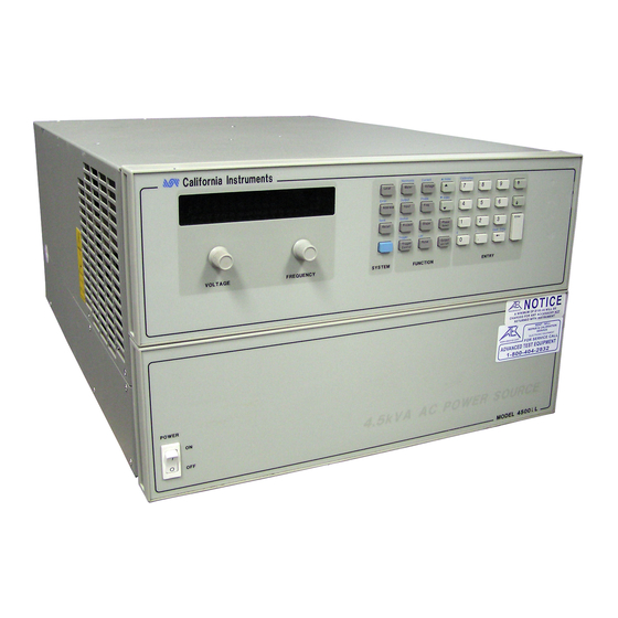
California Instruments iL Series User Manual (100 pages)
AC Power Source/Analyzers
Brand:
California Instruments
| Category:
Power Supply
| Size: 0.97 MB
Table of Contents
Table of Contents
5
Introduction
11
About this Chapter
11
Document Reference
11
Table 1 : User Manual Organization
11
Safety Considerations
12
General Description
12
Figure 1: AC Source Functional Elements
12
Table 2: Il Series Model Numbers
13
Figure 2: AC Source Output Characteristic
15
Options and Accessories
16
Figure 3: AC Source VA Capabilities
16
Table 3 : Options
16
Table 4 : Accessories
16
User-Replaceable Parts
17
Table 5 : Service Part Numbers
17
Installation
18
About this Chapter
18
Inspection
18
Packaging Material
18
Items Supplied
18
Bench Operation
19
Rack Mounting
19
Figure 4 Outline Diagram
19
Input Connections
20
Figure 5 Connecting the Power Cord
21
Figure 6 Output Connections
21
Table 6 : American Wire Gage (AWG) Characteristics
22
Table 7 : AWG Temperature Coefficients
22
Figure 7 Remote Sense Connections
23
OVP Considerations
24
Output Rating
24
Trigger Connections
24
Digital Connections
24
Controller Connections
25
Figure 8 FLT/INH Examples
25
Figure 9 RS232C PC to AC Source Cable Wiring Diagram
27
Table 8 : RS232C DB-9 Connector Pin Assignments
27
Turn-On Checkout
29
Preliminary Checkout
29
Using the Keypad
29
Output Checkout
30
Figure 10 Verification Connections
31
Table 9 : Connection Verification Steps
32
In Case of Trouble
33
Table 10 : Power on Selftest Error Codes
33
Front Panel Operation
35
Introduction
35
Front Panel Description
35
Figure 11 Front Panel, Overall View
35
Table 11 : Display Annunciator Descriptions
36
System Keys
38
Table 12 : Interface Selection
38
Function Keys
39
Figure 13 Function Keys
39
Table 13 : Immediate Action Keys
39
Table 14 : Phase Selection Display Annunciators
40
Table 15 : Measurement Display Readouts
41
Table 16 : Harmonic Measurement Display Readouts
42
Table 17 : Output Control Display Readouts
42
Table 18 : Current Limit Display Readouts
43
Table 19 : Frequency Control Display Readouts
43
Table 20 : Phase Control Display Readouts
44
Table 21 : Waveform Control Display Readouts
44
Table 22 : Pulse Menu Display Readouts
44
Table 23 : Output Menu List Display Readouts
45
Table 24 : Protection Menu List Display Readouts
46
Table 25 : Status Menu List Display Readouts
46
Entry Keys
47
Table 26 : Trigger Control List Display Readouts
47
Table 27 : List Command Display Readouts
47
Figure 14 Entry Keys
48
Examples of Front Panel Programming
49
Table 28 : Setting the Output Voltage Amplitude
50
Table 29 : Setting Individuals Output Phases in Three Phase Mode
51
Table 30 : Setting the Output Frequency
51
Table 31 : Setting Protection Parameters
52
Figure 15 Pulse Transients
53
Table 32 : Programming a Voltage Step Transient
53
Figure 16 List Transients
54
Table 33 : Programming a Voltage Pulse Transient
54
Trigger Delays and Phase Synchronization
55
Table 34 : Programming Transient Lists
55
Figure 17 Trigger Delays and Phase Synchronization
56
Programming Slew Rates
58
Figure 18 Phase Synchronization on Three Phase Sources
58
Figure 19 Programming Slew Rates
59
Measuring Peak Inrush Current
61
Setting the IEEE-488 Address and RS-232C Parameters
62
Saving and Recalling Operating States
63
Specifications
64
Performance Specifications
64
Table 35 : Il Series Performance Specifications
64
IEC Measurement Specifications
65
Table 36 : IEC Measurement Specifications
65
Typical Specifications
66
Table 37 : Il Series Typical Specifications
67
Calibration and Performance Verification
68
Equipment Required
68
Table 38 : Required Calibration Equipment
68
Operation Verification
69
Figure 20 Verification and Calibration Test Setup
69
Table 39 : Voltage Programming Readback Test Steps
70
Table 40 : Current Programming Readback Test Steps
71
Verification Test Checklist
72
Performing the Calibration Procedure
72
Table 41 : Verification Test Checklist
72
Table 42 : Front Panel Calibration Procedure Steps
76
Table 43 : Changing the Calibration Password
77
Table 44 : IEEE-488 Calibration Error Messages
77
Figure 21 Calibration Switches
78
Troubleshooting
79
Introduction
79
Localizing the Problem
79
Troubleshooting Procedure
80
Table 45 : Specific Troubleshooting Procedures
80
Firmware Revisions
81
Table 46 : AC Power Source Troubleshooting Procedure
83
Table 47 : Pin and Signal Voltages at A10 Connectors
83
Figure 22 Troubleshooting Diagram for no Output Present
84
Figure 23 Troubleshooting Diagram for One or more Outputs Missing
85
Principles of Operation
86
Introduction
86
General Description
86
Assembly Descriptions
86
Figure 24 AC Power Source Block Diagram
89
Replaceable Parts
90
Introduction
90
Replaceable Assemblies
90
Other User-Replaceable Parts/Options
91
Options
91
Accessories
91
Table 48 : Replaceable Assemblies
91
Table 49 : User Replaceable Parts
91
Table 50 : Available Options
91
Table 51 : Available Accessories
91
Diagrams
92
Figure 25 Auxiliary Power Supply Parts Location
92
Figure 26 AC Input Board Parts Location
93
Figure 27 Mother Board Parts Location
94
Error Messages
95
Table 52 : Standard Event Status Register (ESR) Bits
95
Table 53 : Standard Event Status Register (ESR) Error Codes
97
Advertisement
Advertisement
Related Products
California Instruments 12000L-1P
California Instruments 12000L-3P
California Instruments 12000L/2-1
California Instruments 12000L/2-3
California Instruments 1251RP Series
California Instruments 13500L/3-1
California Instruments 13500L/3-1P
California Instruments 13500L/3-3
California Instruments 13500L/3-3P
California Instruments 18000L/3-1
California Instruments Categories
Power Supply
AC Power Distribution
Portable Generator
Motherboard
More California Instruments Manuals
Login
Sign In
OR
Sign in with Facebook
Sign in with Google
Upload manual
Upload from disk
Upload from URL