Sign In
Upload
Manuals
Brands
BVM Manuals
Motherboard
BVME4000
BVM BVME4000 Manuals
Manuals and User Guides for BVM BVME4000. We have
1
BVM BVME4000 manual available for free PDF download: User Manual
BVM BVME4000 User Manual (87 pages)
Brand:
BVM
| Category:
Motherboard
| Size: 0 MB
Table of Contents
Table of Contents
5
1 Introduction
11
Scope
11
BVME4000 Part Numbers
11
BVME6000 Part Numbers
11
Memory Module Part Numbers
11
2 Overview
12
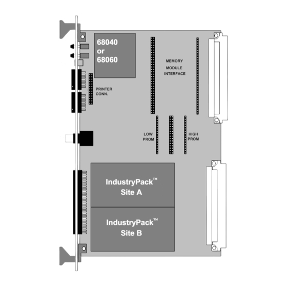
Board Layout
12
Figure 1 Board Layout
12
Features
13
Applications
13
3 Description
14
Block Diagram
14
Figure 2 Block Diagram
14
Processor
15
Memory
15
Real Time Clock
15
Serial Communications
16
Parallel Port
16
SCSI Interface
16
Ethernet Interface
16
Ip I/O
16
Vmebus Interface
17
Vmebus Master
17
Vmebus Slave
17
Interrupts
18
Vmebus Interrupt Handler
18
Internal Interrupts
18
Vmebus Interrupter
18
Vmebus System Controller Functions
19
Power Supply Monitor/Watchdog
19
Local Bus Monitor
19
Configuration Switch
19
Eeprom
19
4 Installation
20
5 Configuration
21
PCB Layout
21
Figure 3 PCB Layout
21
Link and Switch Definitions
22
LK1 Abort Switch Enable
22
LK2 Reset Switch Enable
22
Figure 4 LK1 Abort Switch Enable Location
22
Figure 5 LK2 Reset Switch Enable Location
22
LK3 Vmebus Reset out Enable
23
LK4 Vmebus Reset in Enable
23
Figure 6 LK3 Vmebus Reset out Enable Location
23
Figure 7 LK4 Vmebus Reset in Enable Location
23
LK5 CPU Cache Inhibit
24
LK6 Cheapernet Heart Beat Enable
24
Figure 8 LK5 CPU Cache Inhibit Location
24
Figure 9 LK6 Cheapernet Heart Beat Enable Location
24
LK7,8,9 Ethernet Aui/Cheapernet Select
25
LK10,11,12,14,15 EPROM Size & Type Select
25
Figure 10 LK7,8,9 Ethernet Aui/Cheapernet Select Location
25
Figure 11 LK10,11,12,14,15 EPROM Size & Type Select Location
25
LK13 SCSI Termination Disable
26
LK18,19 CPU 5/3.3V Selection
26
Figure 12 LK13 SCSI Termination Disable Location
26
Figure 13 LK18,19 CPU 5/3.3V Selection Location
26
LK21 SRAM Backup Selection
27
LK22 Vmebus System Controller Enable
27
Figure 14 LK21 SRAM Backup Selection Location
27
Figure 15 LK22 Vmebus System Controller Enable Location
27
Configuration Switch
28
Indicators
28
Green LED - RUNNING
28
Red LED - Vmebus Master Access
28
Figure 16 Configuration Switch Location
28
6 Connector Pinouts
29
JP1 & JP2 Serial Port Connections
29
JP3 Parallel Port Connections
29
Figure 17 JP1 & JP2 Serial Port Connections
29
Figure 18 JP3 Parallel Port Connections
29
JP4 Cheapernet Connector
30
JP4 Optional 10Baset Connector
30
Figure 19 JP4 Optional 10Baset Connector
30
JP5A/B IP A/B Connections
31
Figure 20 IP Connector Pin Numbering Viewed from Solder Side of BVME4000/6000
31
Figure 21 Flat Cable Connector Pin Numbering Viewed from Front of JP5
31
JP7 CPU Fan Power
32
JP8 JTAG Connector
32
J1 SCSI Connections
32
Figure 22 JP7 CPU Fan Power
32
Figure 23 JP8 JTAG Connector
32
Figure 24 J1 SCSI Connections
32
J14 SCSI Peripheral Power Connections
33
P2 I/O Connections
33
Figure 25 J14 SCSI Peripheral Power Connections
33
Protection Fuses
34
Figure 26 Protection Fuse Positions
34
7 Programming
35
Address Map
35
I/O Address Map
36
Memory Module
36
Vmebus Master Access
37
A16:D16 (D08Eo)
37
A16:D32
37
A24:D16 (D08Eo)
37
A24:D32
38
A32:D16
38
A32:D32
38
Sram
39
Eprom
39
SCSI Controller
40
Overview
40
Programming
40
Hardware Specific Considerations
40
SCSI Controller Registers
41
SCSI Electrical Interface
42
Ethernet Controller
43
Overview
43
Programming
43
PORT Access
43
Channel Attention Access
44
Bus Error Handling
44
SYSBUS Byte Requirements
44
Electrical Interface
44
Interrupt Controller
45
Overview
45
Processor Interrupter
45
Vmebus Interrupter
46
Interrupt Controller Registers
46
VMEIRQ Enable Register
46
VMEIRQ Vector Register
46
VMEIRQ Level Register
47
LOCIRQ Enable Register
47
ETHIRQ Enable Register
47
Local IRQ Status Register
48
IP Controller
49
Overview
49
IP Expansion Interface
49
IP Interrupts
49
Memory Space Address Map
50
I/O & ID Space Address Map
51
IP Controller Registers
52
IRQ Level A0 Register
52
IRQ Level A1 Register
52
IRQ Level B0 Register
52
IRQ Level B1 Register
53
IP Clock Speed Select Register
53
IP SYNC Clock Select Register
53
Vmebus Slave Access Controller
55
Overview
55
Standard (A24) & Extended (A32) Accesses
55
Short I/O (A16) Accesses
56
Controlling the Window Size
56
Local Address Generation
56
Address Control Registers
57
A32VBA - A32 Vmebus Base Address Register
57
A32MSK - A32 Vmebus Address Mask Register
57
A24VBA - A24 Vmebus Base Address Register
57
A24MSK - A24 Vmebus Address Mask Register
57
A16VBA - A16 Vmebus Base Address Register
57
A32LBA - A32 Local Base Address Register
57
A24LBA - A24 Local Base Address Register
58
ADDRCTL - Address Control Register
58
Configuration Switch
59
Configuration Switch Layout
59
Configuration Switch Register
59
Figure 27 Configuration Switch Layout
59
Real Time Clock/Timers
60
Overview
60
Hardware Specific Considerations
60
Programming
61
Parallel Port/Timer
62
Overview
62
Port a Usage
62
Port B Usage
62
Port C Usage
64
Handshake Pin Usage
65
MC68230 PI/T Registers
65
Serial Communications Controller
66
Overview
66
Serial Clock Sources
66
Programming
67
8 Specifications
68
On-Board Functions
68
Vmebus Master
68
Vmebus Slave
68
Vmebus System Controller Functions
68
Vmebus Interrupts
69
IP Functions
69
Board Configuration
69
Operating Environment
69
Appendix A Data Sheet & Manual References
70
MC68040/68LC040/68EC040 User's Manual
70
MC68060/68LC060/68EC060 User's Manual
70
82596CA User's Manual
70
53C710 Data Manual & Programmers Guide
70
DP8570A Data Sheet
70
Z85230 User's Manual
70
MC68230 Data Sheet
70
Vmebus Specification
70
RS422/485 Interface Module User's Manual
70
NMC24C02 Data Sheet
71
MEM390 Memory Module User's Manual
71
MEM400 Memory Module User's Manual
71
MEM480 Memory Module User's Guide
71
MEM4SD Memory Module User's Guide
71
EXP100 Quad IP Expansion User's Manual
71
Appendix B CPU Cache Coherency and Bus Snooping
72
Bvme4000 (Mc68040)
72
Bvme6000 (Mc68060)
74
Appendix C Memory Module Pinout
76
Appendix D IP Expansion Interface Pinout
77
Appendix E Thermal Management
78
Appendix F Circuit Diagrams
79
Advertisement
Advertisement
Related Products
BVM BVME6000
BVM BVME310
BVM Bandit arf
BVM Categories
Toy
Computer Hardware
Control Unit
Security System
Accessories
More BVM Manuals
Login
Sign In
OR
Sign in with Facebook
Sign in with Google
Upload manual
Upload from disk
Upload from URL