Sign In
Upload
Manuals
Brands
Bustec Manuals
Matrix Switcher
ProDAQ 6140
Bustec ProDAQ 6140 Matrix Switching Unit Manuals
Manuals and User Guides for Bustec ProDAQ 6140 Matrix Switching Unit. We have
1
Bustec ProDAQ 6140 Matrix Switching Unit manual available for free PDF download: User Manual
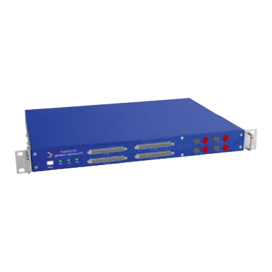
Bustec ProDAQ 6140 User Manual (56 pages)
LXI Matrix Switching Unit
Brand:
Bustec
| Category:
Matrix Switcher
| Size: 3.6 MB
Table of Contents
Table of Contents
3
Reference Documents
7
1 Introduction
9
Overview
9
Figure 1 - Prodaq 6140 LXI Matrix Switching Unit Usage
9
Theory of Operation
10
Applications
10
Monitoring
10
Calibration
11
Fault Insertion
12
2 Specifications
13
Available Versions
13
General
13
Relay Ratings
13
Signal Connectors
13
Network Interface
13
LXI Device Capabilities
13
Environmental Specifications
14
Power Supply
14
3 Getting Started
15
Unpacking and Inspection
15
Front Panel
15
Switches and Indicators
15
Figure 2 - Prodaq 6140-AA Front Panel
15
Figure 3 - Prodaq 6140-AB Front Panel
15
Connectors
16
Rear Panel Connectors
16
Figure 4 - Prodaq 6140 Rear Panel
16
Mounting the Prodaq 6140 in a 19" Rack
17
Device Discovery
17
Accessing the Prodaq 6140 Using Multicast DNS
17
Figure 7 - Bustec VISA Agent Popup-Menu Showing LXI Devices
17
Discovering the Prodaq 6140 Using VXI-11 Broadcast
18
Figure 8 - Prodaq 6140 Discovered Using the VISA Configuration Utility
18
4 Web
19
Instrument Home Page
19
Figure 9 - Instrument Home Page
19
IP Configuration
20
Figure 10 - IP Configuration Page
20
Relay Configuration
22
Figure 11 - Relay Configuration Page
22
Figure 12 - Single Relay Operation
23
Figure 13 - Toggling Several Relay States
23
Relay Operation
23
Figure 14 - Applying the Changes
24
Figure 15 - Open/Close Relays Tab
24
Aliases
25
Figure 16 - Using a List Expression
25
Figure 17 - Selecting a Channel Name (Alias) Field for Editing
26
Figure 18 - Editing the Channel Name (Alias) for Channel X2
26
Figure 19 - Aliases Tab
26
Figure 20 - Presets Tab
26
Presets
26
Figure 21 - Preset Name Display
27
Figure 22 - "Preset Not Saved" Warning
27
Figure 23 - Manage Presets Dialog
27
Device Status
28
Advanced Status
28
Figure 24 - Device Status Page
28
Figure 25 - Advanced Status Page
28
System Log
29
Figure 26 - System Log Page
29
Device Configuration
30
General Settings
30
Figure 27 - Device Configuration Page
30
Figure 28 - General Settings Page
30
Fan Settings
31
Security Settings
31
Figure 29 - Fan Settings Page
31
Firmware Update
32
Figure 30 - Security Settings Page
32
Figure 31 - Firmware Update Page
32
Datasheet and Manual
33
Figure 32 - Firmware Update Progress
33
5 Software Driver
35
Installation
35
Soft Front Panel
35
Starting the Soft Front Panel
35
Figure 33 - Example Installation Dialog
35
Figure 34 - Selecting the Connection Method
36
Figure 35 - Specifying the Instrument Address
36
Operating the Soft Front Panel
37
Figure 36 - Demo Mode Model Selection
37
Figure 37 -Soft Front Panel Application User Interface
38
Figure 38 - Switching a Relay to Its "Closed" State
38
Figure 39 - Relays X3, X4, Y3 and Y4 Are Toggled, but Not Switched on the Prodaq 6140
39
Figure 40 - after Apply Button was Pressed
39
Figure 41 - Relay Context Menus
40
Figure 42 - Using a List Expression
40
Figure 43 - Selecting a Channel Name (Alias) Field for Editing
41
Figure 44 - Editing the Alias for Channel X1
41
Figure 45 - Alias Context Menu Example
41
Figure 46 - Save Preset Dialog
42
Figure 47 - Load Preset Dialog
42
Figure 48 - Preset Name Display
42
Figure 49 - "Preset Not Saved" Warning
43
Figure 50 - Manage Presets Dialog
43
Using the Vxiplug&Play Driver
44
Connecting to the Device
44
Figure 51 - Connecting to the Prodaq 6140
44
Operating Relays
45
Figure 52 - Operating a Relay
45
Figure 53 - Switching Multiple Relays
47
Using the Internal Voltage Reference
48
Figure 54 - Setting the State of All Relays
48
Storing and Retrieving Aliases
49
Figure 55 - Using the Internal Voltage Reference
49
Managing Presets
50
6 Connector Pin-Outs
51
Signal Channels X1 - X96 (200-Pin Molex LFH Connector)
51
Signal Channels X97 - X192 (200-Pin Molex LFH Connector)
52
Signal Channels Y1 - Y96 (200-Pin Molex LFH Connector)
53
Signal Channels Y97 - Y192 (200-Pin Molex LFH Connector)
54
Rear Bus Daisy-Chaining
55
Advertisement
Advertisement
Related Products
Bustec ProDAQ 6150
Bustec ProDAQ 3120
Bustec ProDAQ 3424
Bustec ProDAQ 3150
Bustec ProDAQ 3020 USB 2.0 VXIbus Slot-0
Bustec ProDAQ 3202
Bustec ProDAQ 3411
Bustec Categories
Network Hardware
Motherboard
Recording Equipment
Media Converter
Matrix Switcher
More Bustec Manuals
Login
Sign In
OR
Sign in with Facebook
Sign in with Google
Upload manual
Upload from disk
Upload from URL