Table of Contents
Advertisement
Quick Links
Advertisement
Table of Contents

Summary of Contents for Bustec ProDAQ 6140
- Page 1 ProDAQ LXI Instruments ProDAQ 6140 LXI Matrix Switching Unit PUBLICATION NUMBER: 6140-XX-UM-1000 Copyright, © 2017, Bustec Production, Ltd. Bustec Production, Ltd. Bustec House, Shannon Business Park, Shannon, Co. Clare, Ireland Tel: +353 (0) 61 707100, FAX: +353 (0) 61 707106...
- Page 2 Production Ltd, be used, in whole or in part to solicit quotations from a competitive source or used for manufacture by anyone other than Bustec Production Ltd. The information herein has been developed at private expense, and may only be used for...
-
Page 3: Table Of Contents
Switches and Indicators .................... 13 3.2.2. Connectors ....................... 14 3.3. Rear Panel Connectors ....................14 Mounting the ProDAQ 6140 in a 19” Rack ..............15 3.4. 3.5. Device Discovery ......................15 3.5.1. Accessing the ProDAQ 6140 using Multicast DNS ........... 15 3.5.2. - Page 4 User Manual ProDAQ 6140 LXI Matrix Switching Unit 4.7.1. General Settings ....................... 28 4.7.2. Fan Settings ......................29 4.7.3. Security Settings ....................... 29 4.7.4. Firmware Update ...................... 30 4.8. Datasheet and Manual Pages ..................31 5. Software Driver ......................33 5.1.
- Page 5 Figure 38 - Switching a Relay to its “Closed” State ____________________________________ 36 Figure 39 - Relays X3, X4, Y3 and Y4 are toggled, but not switched on the ProDAQ 6140 ____ 37 Figure 40 - After Apply Button was pressed _________________________________________ 37...
- Page 6 User Manual ProDAQ 6140 LXI Matrix Switching Unit Figure 56 - Setting an Alias ______________________________________________________ 48 Figure 57 - “X”/”Y” Signal Connectors Pin Number Assignment __________________________ 49 Figure 6-58 Rear panel view of Bus Daisy Chain connector _____________________________ 53 Copyright © 2017, Bustec Production Ltd.
-
Page 7: Reference Documents
ProDAQ 6140 LXI Matrix Switching Unit User Manual Reference Documents Title Number Bustec VISA Library and Tools 8200-XX-UM ProDAQ 3202 Voltage Reference Datasheet 3202-XX-DS Glossary - Digital-to-Analog Converter FIFO - First-in First-out Memory - 16-bit number representing an analog value... - Page 8 User Manual ProDAQ 6140 LXI Matrix Switching Unit (This page was intentionally left blank.) Copyright © 2017, Bustec Production Ltd. Page 6 of 56...
-
Page 9: Introduction
The ProDAQ 3202 Voltage Reference plug-in can be installed in the unit and can be connected to either one of the four bus lines. The ProDAQ 6140 LXI Matrix Switching Unit is a fully compliant LXI device supporting all LXI core functions via a Gigabit LAN interface. -
Page 10: Theory Of Operation
Located between a data acquisition and control system and the device under test (DUT), the ProDAQ 6140 LXI Matrix Switching Unit can be used for a variety of applications. In its default mode, the unit simply connects all channels of the data acquisition and control system to the... -
Page 11: Calibration
NOTE The ProDAQ 3202 can only be installed in the factory. If your application wants to make use of it, you need to order it together with the ProDAQ 6140 initially or send the ProDAQ 6140 back for the installation. -
Page 12: Fault Insertion
ProDAQ 6140 LXI Matrix Switching Unit 1.6. Fault Insertion The ProDAQ 6140 can be used to create a number of hardware fault conditions commonly used in hardware fault insertion testing for mission critical systems where such fault conditions must lead to a known, deterministic response. -
Page 13: Specifications
ProDAQ 6140 LXI Matrix Switching Unit User Manual 2. Specifications 2.1. Available Versions Versions 6140-AA LXI Matrix Switching Unit for 96 signal channels and 4 bussed channels 6140-AB LXI Matrix Switching Unit for 192 signal channels and 4 bussed channels 2.2. -
Page 14: Environmental Specifications
User Manual ProDAQ 6140 LXI Matrix Switching Unit 2.7. Environmental Specifications Temperature 0 °C to +50 °C (operational) -40 °C to +70 °C (storage only) Humidity 5% - 95% (non-condensing) 2.8. Power Supply Input Voltage 85-265 VAC, 47-63 Hz Current Consumption 1.6 A max. -
Page 15: Getting Started
ProDAQ 6140 is switched on. The "LAN" indicator is a bi-color LED. It is used to identify the ProDAQ 6140 via its WEB interface or its Soft Front Panel and to indicate a LAN failure. When used for LAN identification, it flashes green, while a LAN failure is indicated by a constant red light. -
Page 16: Connectors
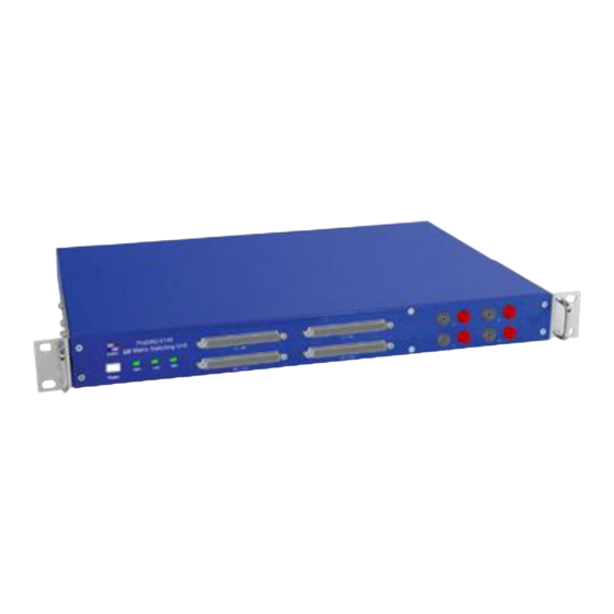
ProDAQ 6140 LXI Matrix Switching Unit 3.2.2. Connectors The ProDAQ 6140 features two (ProDAQ 6140-AA) or four (ProDAQ 6140-AB) LFH connectors to connect to the “X” and “Y” channels of the relay matrix and four pairs of 4mm banana sockets to connect to the “A”, ”B”, ”C”... -
Page 17: Mounting The Prodaq 6140 In A 19" Rack
Please refer to the ProDAQ 5725 assembly instructions for usage. 3.5. Device Discovery The most convenient way to start accessing a ProDAQ 6140 unit is to use one of the zero- configuration networking tools for your host computer that make use of the multicast DNS service supported by the ProDAQ 6140. -
Page 18: Discovering The Prodaq 6140 Using Vxi-11 Broadcast
VXI-11 protocol. After starting the configuration utility, select the “Network Instruments” tab and click on the button “Find Instruments”. To discover a ProDAQ 6140, the device type “INST” with device number 0 must be included in the search criteria shown in the “Find Network Instruments” dialog before you click the button “Search for Instruments”. -
Page 19: Web
The ProDAQ 6140 features an embedded web server, which allows you to configure and operate the ProDAQ 6140 by using a standard web browser from any host computer in your network. To make use of the complete functionality of the embedded web interface, the browser will need to have its JavaScript support enabled. -
Page 20: Ip Configuration
ProDAQ 6140 LXI Matrix Switching Unit 4.2. IP Configuration The IP Configuration Page allows you to change the settings for the ProDAQ 6140's LAN interface. Figure 8 - IP Configuration Page The IP Configuration page shows the current settings for the instruments LAN interface and allows you to change and store the following settings: User defined hostname for the device (without domain). - Page 21 The device has a LAN reset mechanism that restores all the IP back to factory defaults. In order to reset the settings press the “RST” button that can be found in the rear panel of the ProDAQ 6140 and wait for the device to reboot.
-
Page 22: Relay Configuration
User Manual ProDAQ 6140 LXI Matrix Switching Unit 4.3. Relay Configuration The Relay Configuration page provides user-friendly control over the whole relay matrix. The graphical tool is divided into three parts (from top to bottom): - A command area with three tabs allowing to select preset commands, relay group switch commands and alias settings commands. -
Page 23: Relay Operation
ProDAQ 6140 LXI Matrix Switching Unit User Manual 4.3.1. Relay Operation To change the state of the relays, you can operate single relays by just clicking a relay in the displayed schematic or you can operate groups of relays by using the commands available in the “Open/Close Relays”... -
Page 24: Figure 14 - Applying The Changes
User Manual ProDAQ 6140 LXI Matrix Switching Unit Figure 11 shows an example where the states of the relays X3, X4, Y3 and Y4 were toggled, but the apply button wasn’t used to update the relays on the device. Relays X3 and Y3 were changed from the “open”... -
Page 25: Aliases
ProDAQ 6140 LXI Matrix Switching Unit User Manual The standard commands in the drop-down list allow opening all relays, opening all relays in one of the columns (X, A, B, C, D, “Y”) or closing all relays in either the X or Y columns. -
Page 26: Presets
Figure 17 - Aliases Tab 4.3.3. Presets The entire device configuration of the ProDAQ 6140 can be stored on the device as a preset under a name and reapplied by loading it. A device configuration (preset) consists of the relay settings, assigned aliases as well as a voltage reference setting (if installed). -
Page 27: Figure 21 - Preset Name Display
“Load”. This operation updates both the device and the schematic editor. WARNING When a preset is loaded, it is automatically applied on the ProDAQ 6140 device. All the relays are set accordingly to the preset’s configuration. If a preset was loaded, its name is displayed in the lower right corner next to the “Apply” button (see Figure 19). -
Page 28: Device Status
User Manual ProDAQ 6140 LXI Matrix Switching Unit 4.4. Device Status The Device Status page displays the general status of the device like network connection status, temperature readings, power monitor status and list of open connections. Figure 22 - Device Status Page 4.5. -
Page 29: System Log
ProDAQ 6140 LXI Matrix Switching Unit User Manual Figure 23 shows an example of the Advanced Status page showing the output of the embedded “ifconfig” command. To select any of the available advanced status information, select one of the items from the list and select the “Refresh” button. The following advanced status information is currently available: Displays the output of the embedded “ifconfig”... -
Page 30: Device Configuration
User Manual ProDAQ 6140 LXI Matrix Switching Unit 4.7. Device Configuration The Device Configuration page allows you to change several parameters of the internal configuration of the device. In addition it allows you to reboot the device or update its firmware. -
Page 31: Fan Settings
ProDAQ 6140 LXI Matrix Switching Unit User Manual 4.7.2. Fan Settings This page allows to configure how the unit operates its build-in fans. Figure 27 - Fan Settings Page There are two modes of operation: The fans run at a low speed. This setting is not recommended Silent when the ambient temperature is high. -
Page 32: Firmware Update
ProDAQ 6140 LXI Matrix Switching Unit Figure 28 - Security Settings Page 4.7.4. Firmware Update To update the firmware on the ProDAQ 6140, use the “Update Firmware” button on the “Device Configuration” page. Figure 29 - Firmware Update Page Before you can start a firmware update, make sure that the file is available on the host computer where you run the internet browser. -
Page 33: Datasheet And Manual
ProDAQ 6140. 4.8. Datasheet and Manual Pages The “Datasheet” and “Manual” pages allow you to view the ProDAQ 6140 datasheet and user manual. Page 31 of 56... - Page 34 User Manual ProDAQ 6140 LXI Matrix Switching Unit (This page was intentionally left blank.) Copyright © 2017, Bustec Production Ltd. Page 32 of 56...
-
Page 35: Software Driver
5.1. Installation In order to install the software, run the ProDAQ 6140 installer package, 32 or 64 bit – appropriate to the operating system, and accept the license agreement. The files are copied by default to the IVIStandardRootDir respectively the VXIPNPPATH location. -
Page 36: Figure 34 - Selecting The Connection Method
IP address or host name of the instrument. Figure 33 - Specifying the Instrument Address If no ProDAQ 6140 is available in your system or to create/edit presets, the soft front panel application can be run in demo (offline) mode. -
Page 37: Operating The Soft Front Panel
The main purpose for working off-line is that it is possible to create and modify presets without physical connection to ProDAQ 6140. A preset can be imported from and exported to a file. The file for import can be taken from the real device for modification and the exported file can be uploaded to ProDAQ 6140. -
Page 38: Figure 37 -Soft Front Panel Application User Interface
Figure 36 - Switching a Relay to its “Closed” State The relays are not immediately switched on the ProDAQ 6140. Those being in a different state than is currently set on the device are additionally marked with a yellow frame. The last changes that haven’t been written to the device yet can be reverted by pressing “Undo”... -
Page 39: Figure 39 - Relays X3, X4, Y3 And Y4 Are Toggled, But Not Switched On The Prodaq 6140
ProDAQ 6140 LXI Matrix Switching Unit User Manual Figure 37 - Relays X3, X4, Y3 and Y4 are toggled, but not switched on the ProDAQ 6140 Figure 38 - After Apply Button was pressed Page 37 of 56 Copyright © 2017, Bustec Production Ltd. -
Page 40: Figure 41 - Relay Context Menus
User Manual ProDAQ 6140 LXI Matrix Switching Unit Toggling the relays independently may sometimes be time consuming. In such a case the group switching options available in the context menus for each of the relays are useful. They allow opening all relays, or opening the whole column: X, Y, A, B, C , or D. Also closing the whole X or Y column is possible. -
Page 41: Figure 43 - Selecting A Channel Name (Alias) Field For Editing
Once clicked, a text edit field allows you to enter or edit the alias. Press “Enter” to save the change made. Once an alias is edited, the change is immediately stored on the ProDAQ 6140 device. Each alias can be up to 31 characters long. -
Page 42: Figure 46 - Save Preset Dialog
6140 device or to run the Soft Front Panel offline in demo mode. WARNING When a preset is loaded, it is automatically applied on the ProDAQ 6140 device. All the relays are set accordingly to the preset’s configuration. If a preset was loaded or saved, its name is displayed in the lower right corner next to the “Apply”... -
Page 43: Figure 49 - "Preset Not Saved" Warning
More preset handling options are available when the “Manage Presets…” button is pressed. It opens a dialog where it is possible to delete presets or export them from the ProDAQ 6140 device to files on local or network storage device. The opposite is also possible – the user can import previously stored presets to ProDAQ 6140. -
Page 44: Using The Vxiplug&Play Driver
ProDAQ 6140 LXI Matrix Switching Unit 5.3. Using the VXIplug&play Driver This chapter shows how to operate the ProDAQ 6140 LXI Matrix Switching Unit using the VXIplug&play driver. The code section(s) shown are used to explain the basic functionality only, complete examples can be found in the “Examples”... -
Page 45: Operating Relays
50, ). As parameters you need to specify the relay column (channel I/Os “X”, “Y” or bus lines “A”, “B”, “C” and “D”), the row (1-96 for ProDAQ 6140 versions “AA” and “BA” or 1-192 for ProDAQ 6140 versions “AB” and “BB”) and the state the relay shall be switched to. The relay column as well as the relay state can be specified using a predefined macro from the bu6140.h include file or the... - Page 46 User Manual ProDAQ 6140 LXI Matrix Switching Unit this function, first all relays specified in the “open” mask are switched to their “open” state, then the relays specified in the “close” mask are switched to their “closed” state. Array Index Channel I/O “X”...
-
Page 47: Figure 53 - Switching Multiple Relays
52, ). It expects as the second parameter an array of 32-bit values where each bit of the values represent the state of a relay in the matrix. For ProDAQ 6140 versions “AA” and “BA” the array must contain 18 values; for the versions “AB” and “BB” it must contain 36 values. A bit equal to one (1) will set the relay to its “closed”... -
Page 48: Using The Internal Voltage Reference
User Manual ProDAQ 6140 LXI Matrix Switching Unit bu6140_getMatrixState() existing state of the matrix can be retrieved using the function (see also Figure 52, ). #include <visa.h> #include <bu6140.h> main (int argc, char **argv) ViStatus status; ViSession session; ViChar descr[256];... -
Page 49: Storing And Retrieving Aliases
ProDAQ 6140 LXI Matrix Switching Unit User Manual #include <visa.h> #include <bu6140.h> main (int argc, char **argv) ViStatus status; ViSession session; ViChar descr[256]; /* ... */ /* set the output of the voltage reference to 4.5 Volt */ if ((status = bu6140_setVoltRefOutput (session, 4.5)) < VI_SUCCESS) ... -
Page 50: Managing Presets
Figure 54 - Setting an Alias 5.3.5. Managing Presets The actual state of the ProDAQ 6140 unit - consisting of the relay states, list of aliases, voltage reference output setting (if installed) and voltage reference connection setting (if installed) - can be named and stored on the device. -
Page 51: Connector Pin-Outs
ProDAQ 6140 LXI Matrix Switching Unit User Manual 6. Connector Pin-outs 6.1. Signal channels X1 - X96 (200-pin Molex LFH connector) Figure 55 - “X”/”Y” Signal Connectors Pin Number Assignment Signal Signal Signal Signal -X25 -X49 -X73 +X25 +X49 +X73... -
Page 52: Signal Channels X97 - X192 (200-Pin Molex Lfh Connector)
User Manual ProDAQ 6140 LXI Matrix Switching Unit Signal Signal Signal Signal +X19 +X43 +X67 +X91 -X20 -X44 -X68 -X92 +X20 +X44 +X68 +X92 -X21 -X45 -X69 -X93 +X21 +X45 +X69 +X93 -X22 -X46 -X70 -X94 +X22 +X46 +X70 +X94... -
Page 53: Signal Channels Y1 - Y96 (200-Pin Molex Lfh Connector)
ProDAQ 6140 LXI Matrix Switching Unit User Manual Signal Signal Signal Signal +X115 +X139 +X163 +X187 -X116 -X140 -X164 -X188 +X116 +X140 +X164 +X188 -X117 -X141 -X165 -X189 +X117 +X141 +X165 +X189 -X118 -X142 -X166 -X190 +X118 +X142 +X166 +X190... -
Page 54: Signal Channels Y97 - Y192 (200-Pin Molex Lfh Connector)
User Manual ProDAQ 6140 LXI Matrix Switching Unit Signal Signal Signal Signal +Y20 +Y44 +Y68 +Y92 -Y21 -Y45 -Y69 -Y93 +Y21 +Y45 +Y69 +Y93 -Y22 -Y46 -Y70 -Y94 +Y22 +Y46 +Y70 +Y94 -Y23 -Y47 -Y71 -Y95 +Y23 +Y47 +Y71 +Y95... -
Page 55: Rear Bus Daisy-Chaining
ProDAQ 6140 LXI Matrix Switching Unit User Manual Signal Signal Signal Signal +Y116 +Y140 +Y164 +Y188 -Y117 -Y141 -Y165 -Y189 +Y117 +Y141 +Y165 +Y189 -Y118 -Y142 -Y166 -Y190 +Y118 +Y142 +Y166 +Y190 -Y119 -Y143 -Y167 -Y191 +Y119 +Y143 +Y167 +Y191...
Need help?
Do you have a question about the ProDAQ 6140 and is the answer not in the manual?
Questions and answers