Sign In
Upload
Manuals
Brands
BUSKRO Manuals
Label Maker
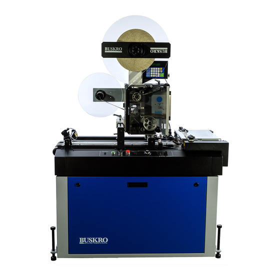
BK730-2
BUSKRO BK730-2 Manuals
Manuals and User Guides for BUSKRO BK730-2. We have
1
BUSKRO BK730-2 manual available for free PDF download: User Manual
BUSKRO BK730-2 User Manual (157 pages)
Tabber
Brand:
BUSKRO
| Category:
Label Maker
| Size: 6 MB
Table of Contents
Table of Contents
3
1 General Information
5
Description
6
Features
7
High Speed Production
7
Integration with Buskro and
7
Rd Party Equipment
7
Simplified Mechanical Adjustments
7
Software Controlled Tabber/Labeler Head Functions
8
Construction, Safety Features, and Maintenance
8
Tabbing Quality Considerations
8
Tabber/Labeler Base Specifications
10
Tabber/Labeler Head Specifications
11
Tabber/Labeler Base and Head Dimensions
12
2 BK730-2 Base
14
Instrument Panel Functions
15
Feed Disable Control
15
START Pushbutton
16
STOP Pushbutton
16
JOG/RUN Selector
16
Speed Control Module Connector
17
POWER Rocker Switch (Main Power)
17
HEAD Rocker Switch (Head Power)
18
Production Speed Regulation Dial
18
Tabber Connection Receptacle Panel
19
Upstream and Downstream Installation Instructions
20
Physical Alignment of Upstream/Downstream Equipment
20
Electrical Connection to Upstream/Downstream Equipment
21
The Base Control Board (P/N 9102380A)
22
The Speed Control Board (P/N 9102421)
25
Product Setup Instructions
31
To Adjust the Base Speed for Smooth Product Transfer
31
Skidbar and Material Side Guide Adjustments
32
Product Thickness Adjustment (Upper Transport)
36
Advanced Setup Instructions
37
Crease and Pinch Roller Adjustment
37
Maintenance Schedule
40
Mechanical Adjustments
41
Tabber/Labeler Head Lateral Positioning
42
Peel Point Setup for Different Product Thickness
43
Peel Point Lateral Adjustment
44
Label Spool Threading and Lateral Positioning
45
Despool Brake Adjustment
47
Labeler Connector Panel
48
Wide Labeler Guidelines (BK731-2WL & UBK-731-WL)
49
Importance of the Right & Left Side Guides
49
The Tabber Skidbar Assembly
50
Wide Label Pressure Roller
52
Label Backer Tension
53
Idler Roller Setup
54
Fanfold Supply Tray Assembly (P/N 9102031A)
55
Independent Nip Roller Height Adjustment
56
4 User Interface
58
Tabber/Labeler Keypad Interface
59
Keypad Setup Menu
60
Front or Back Product Sensor Selection
60
Adjustment of the Product Sensor Position
61
Production Counter Resetting
61
Software Version
62
Factory Reset
62
Life Count Display
62
Form Size Error
63
Displaying Metric Units on the Operator Keypad
63
Keypad Test Menu
64
Keypad Position Menu
66
Label Spacing Option
66
Number of Labels
67
Product Length Entry
67
Manual Label Position
68
Keypad Labels Menu
69
Label Pitch Auto and Manual Setting
69
Type of Label Setting
71
Peel Point Sensor Adjustment
71
Peel Point Sensor Nudge Factor
72
Operational Controls
72
Online/Offline Status
72
Product Count, Production Rate, and Belt Speed Display
73
Error Conditions
73
Maintenance Schedule
74
Assembly Drawings a
75
Table A-1: BK730A-2 Tabbing System
79
Figure A-1: BK730A-2 Tabbing System
80
Table A-2: Tabber Skidbar Assembly (330740A
81
Figure A-2: Tabber Skidbar Assembly (330740A
82
Figure A-3: Jam Switch Assembly, Tabber (603520A
83
Table A-3: Jam Switch Assembly, Tabber (603520A
83
Figure A-4: Cable, Conveyor Interconnect(614530A
84
Table A-4: Cable, Conveyor Interconnect(614530A
84
Figure A-5: Front Mounting Rail Assembly (9101077A
85
Table A-5: Front Mounting Rail Assembly (9101077A
85
Figure A-6: Output Cable Assembly, BK730-2 (9101656A
86
Table A-6: Output Cable Assembly, BK730-2 (9101656A
86
Figure A-7: Power Cable Assembly, BK730-2 (9101657A
87
Table A-7: Power Cable Assembly, BK730-2 (9101657A
87
Figure A-8: Encoder Cable Assembly, BK730-2 (9101658A
88
Table A-8: Encoder Cable Assembly, BK730-2 (9101658A
88
Figure A-9: Photo F/B Cable Assembly, BK730-2 (9101659A
89
Table A-9: Photo F/B Cable Assembly, BK730-2 (9101659A
89
Figure A-10: Jam Cable Assembly (9101660A
90
Table A-10: Jam Cable Assembly (9101660A
90
Table A-11: Tabber Head Assembly, Version 2 (BK731A-2
91
Figure A-11: Tabber Head Assembly, Version 2 - Page 1 of 2 (BK731A-2
92
Figure A-12: Tabber Head Assembly, Version 2 Page 2 of 2 (BK731A-2
93
Figure A-13: Unwind Assembly (9101051A
94
Table A-12: Unwind Assembly (9101051A
94
Figure A-14: Rewind Assembly (9101052A
95
Table A-13: Rewind Assembly (9101052A
95
Figure A-16: Idler Roller Assembly (9101060A
97
Table A-15: Idler Roller Assembly (9101060A
97
Figure A-17: Lower Pivot Arm Assembly (9101069A
98
Table A-16: Lower Pivot Arm Assembly (9101069A
98
Figure A-18: Peel Point Base Assembly (9101081A
99
Table A-17: Peel Point Base Assembly (9101081A
99
Figure A-19: Front Cover Assembly (9101111A
100
Table A-18: Front Cover Assembly (9101111A
100
Figure A-21: Keypad Mounting Rail Assembly (9101121A
102
Table A-20: Keypad Mounting Rail Assembly (9101121A
102
Table A-23: Tabber Connector Plate Harness (9101134A
105
Figure A-24: Tabber Connector Plate Harness (9101134A
106
Figure A-26: Oscillating Idler Assembly (9101233A
108
Table A-25: Oscillating Idler Assembly (9101233A
108
Table A-27: Peel Point Assembly (9101264A
110
Figure A-28: Peel Point Assembly (9101264A
111
Figure A-29: Suspension Base Block Assembly (9101565A
112
Table A-28: Suspension Base Block Assembly (9101565A
112
Figure A-30: Terminal Block Assembly, BK731-2 (9101575A
113
Table A-29: Terminal Block Assembly, BK731-2 (9101575A
113
Figure A-32: 2-Phase Stepper Motor Driver Assembly (9103542A
115
Table A-31: 2-Phase Stepper Motor Driver Assembly (9103542A
115
Table A-33: Base, BK730-2, 115 VAC (9103970A
117
Figure A-34: Base, BK730-2, 115 VAC (9103970A
118
Figure A-35: Base, BK730-2, 115 VAC (9103970A
119
Table A-34: Upper Transport Assembly (212735A
120
Figure A-36: Upper Transport Assembly (212735A
121
Table A-35: Tabletop Assembly (325530A
122
Figure A-37: Tabletop Assembly (325530A
123
Table A-36: Tabber Base Mechanical Assembly (330730A
124
Figure A-38: Tabber Base Mechanical Assembly (330730A
125
Figure A-39: Height Adjustment Screw Assembly (100540A
126
Table A-37: Height Adjustment Screw Assembly (100540A
126
Figure A-40: Bridge Handwheel Assembly (438311A
127
Figure A-41: Sensor, Magnetic, NO/NC Cable (9101557A
128
Table A-39: Sensor, Magnetic, NO/NC Cable (9101557A
128
Figure A-42: Tabber Motor Assembly (530707A
129
Table A-40: Tabber Motor Assembly (530707A
129
Table A-46: Base Cabinet Assembly (9104015A
135
Figure A-48: Base Cabinet Assembly (9104015A
136
Figure A-49: Cable, Rear Panel, Upstream to BCB (9104143A
137
Table A-47: Cable, Rear Panel, Upstream to BCB (9104143A
137
Figure A-50: Cable, Downstream to BCB (9104144A
138
Table A-48: Cable, Downstream to BCB (9104144A
138
Advertisement
Advertisement
Related Products
BUSKRO BK731
BUSKRO BK760
BUSKRO BK76IB
Buskro BK7IB-2
BUSKRO BK703
BUSKRO Apollo BK-IDM-4H
BUSKRO Categories
Label Maker
Digital Mailing system
Printer
Printer Accessories
Accessories
More BUSKRO Manuals
Login
Sign In
OR
Sign in with Facebook
Sign in with Google
Upload manual
Upload from disk
Upload from URL