Sign In
Upload
Manuals
Brands
Burford Manuals
Industrial Equipment
2100
Burford 2100 Manuals
Manuals and User Guides for Burford 2100. We have
1
Burford 2100 manual available for free PDF download: Manual
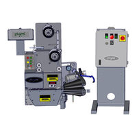
Burford 2100 Manual (221 pages)
ELECTRONIC SERVO TYER MODEL
Brand:
Burford
| Category:
Industrial Equipment
| Size: 30.08 MB
Table of Contents
Section 1
4
Safety Precautions
2
Disclaimer Warning
3
Table of Contents
4
Table of Flow Charts
11
Chapter 1: Introduction
14
Specifications
15
Models
15
Conveyor Requirements
16
Bag Neck Length Requirements
17
Unit Overview
18
E-Stop Location
19
Chapter 2: Key Components
22
Tyer Head
22
Control Panel
22
Needle
23
Twister Hook
24
Holder / Shear
25
Holder / Shear, Cont'D
26
Holder / Shear, Cont'D
27
Bag Switch
28
Ribbon Dispense Encoder
29
Ribbon Guide
30
Gathering Belts
31
Belt Speed Switch
31
Main Enclosure
32
Main Disconnect
32
Ribbon Tension Assembly
33
Ribbon Tension Spring
33
Brake
34
Dancer Arm
35
Ribbon Drop Sensor
35
Gathering Brush
36
Adjustment Knob
36
Pressure Regulator
37
Bag Stop
37
Optional Key Components
38
Package Detection Sensor
39
Speed Follower Encoder
40
Operator Display
41
Bag Tail Blower
41
Stand
42
Conveyor
42
Chapter 3: Installation
44
Mechanical Installation
44
Mechanical Installation, Cont'D
45
Mechanical Installation, Cont'D
46
Mechanical Installation, Cont'D
47
Electrical Interconnections
48
Bagger Enable Circuit (Safety Interlock)
48
Bagger-Active Circuit
49
Counter Output / External Counter Output
49
Installation Arrangements
50
Chapter 4: Operation Procedures
52
Theory of Operation
52
Control Panel
53
STOP" Pushbutton
54
RUN" Pushbutton
54
THREAD" Pushbutton
54
MOTORS ENABLED" Light
55
INITIALIZED" Light
55
TYER FAULT" Light
55
BELT SPEED" Push Wheel Switch
56
Main Enclosure
57
Package Recognition System
58
Package Detection System (PDS)
59
Dual Ribbon Spool System
60
Ribbon Tension
61
Changing and Threading the Ribbon
62
Changing and Threading the Ribbon, Cont'D
63
Changing and Threading the Ribbon,Cont'D
64
Changing and Threading the Ribbon,Cont'D
65
Speed Following Feature
66
Daily Startup
67
Daily Startup, Cont'D
68
Chapter 5: Timing and Adjustments
70
Bag Switch Adjustment
70
Holder Shear Adjustment
71
Shuttle Bar Alignment
72
Gathering Belts Tension Adjustment
73
Gathering Belts Speed Adjustment
74
Belt Guide Tension Adjustment
75
Gathering Belts Teeth Mesh
75
Proximity Sensor Adjustment
76
Proximity Sensor Adjustment, Cont'D
77
Gathering Brush Tension Adjustment
78
Gathering Brush Air Adjustments
79
Ribbon Dispenser Adjustment
79
Ribbon Dispenser Adjustment, Cont'D
80
Ribbon Dispenser Adjustment, Cont'D
81
Needle Roller Replacement
82
Needle Roller Replacement, Cont'D
83
Spacing of Twister Hook Shaft to Tip of Holder Shear
84
Adjusting Tie Tightness
85
Nominal Adjustment
86
Adjusting the Eccentric Ribbon Guide
86
Adjusting the Belt Pulley
86
Auxiliary DIP Switch Settings
87
CPU DIP Switch Settings
88
Fuse and Circuit Breaker List
89
Counter Output
90
PROM Replacement
90
PROM Replacement, Cont'D
91
PROM Replacement, Cont'D
92
Chapter 6: Communications
94
Terminal Option
94
Communicating with the Controller
94
Burford TERMINAL Program
95
Terminal Program in Microsoft Windows Version 3.0 or
96
Servo Tyer Controller and PC Communication Cable
97
Servo Tyer Commands
98
Starting the Servo Tyer
98
When You Start the Servo Tyer, Cont'D
99
TIME and DATE Commands
100
TROUBLE Command
100
QUERY Command
101
QUERY Command, Cont'D
102
RESET Command
103
DEBUG Command
103
HOME Command
104
DISPENSE Command
104
DISPENSE Command, Cont'D
105
(+) Command
105
(+) Command, Cont'D
106
Chapter 7: Troubleshooting
108
Troubleshooting Considerations
108
Diagnostic Led's
109
Diagnostic Led's, Cont'D
110
Seven Segment LED Error Codes
112
Seven Segment LED, Error Codes, Cont'D
113
Seven Segment LED, Error Codes, Cont'D
114
Audible Alarm Codes
115
Troubleshooting Flow Charts
115
Flow Chart 0-1 Unit will Not Power up and Initialize
116
Flow Chart 0-2 Gathering Belts will Not Run
117
Flow Chart 0-3 Brush Motor Not Running
118
Flow Chart 0-4 Motor for Gathering Brushes Won't Run
119
Flow Chart 0-5 Blower Motor Not Running
120
Flow Chart 0-6 Tyer Not Allowing Bagger to Start
121
Flow Chart 0-7 E001 Error Code
122
Flow Chart 0-8 E101 Error Code
123
Flow Chart 0-9 E102 Error Code
124
Flow Chart 0-10 E111 Error Code
125
Flow Chart 0-11 E112 or E113 Error Code
126
Flow Chart 0-12 E114 Error Code
127
Flow Chart 0-13 E115 or E116 Error Code
128
Flow Chart 0-14 E117 Error Code
129
Flow Chart 0-15 E121 Error Code
130
Flow Chart 0-16 E122 or E123 Error Code
131
Flow Chart 0-17 E124 Error Code
132
Flow Chart 0-18 E125 or E126 Error Code
133
Flow Chart 0-19 E127 Error Code
134
Flow Chart 0-20 E131 Error Code
135
Flow Chart 0-21 E132 or E133 Error Code
136
Flow Chart 0-22 E134 Error Code
137
Flow Chart 0-23 E135 and E136 Error Code
138
Flow Chart 0-24 E137 Error Code
139
Flow Chart 0-25 E146 Error Code
140
Flow Chart 0-26 E151-169 Error Codes
141
Flow Chart 0-27 E201 Error Code
142
Flow Chart 0-28 E300 Error Code
143
Flow Chart 0-29 Excessive Ribbon Drops
144
Flow Chart 0-30 Ribbon Drops During Homing Sequence
145
Flow Chart 0-31 Needle Punches Holes through Bag Neck
146
Flow Chart 0-32 Bags Drag Hard against Flight
147
Flow Chart 0-33 Tyer Aborts Cycle on Good Package
148
Flow Chart 0-34 Excessive Belt Fuse Failure
149
Flow Chart 0-35 Twist Tie Breaks During Tying
150
Flow Chart 0-36 Ties Not Centered on Product
151
Flow Chart 0-37 Two Packages Tied Together
152
Flow Chart 0-38 Ribbon Wraps Around Hook Shaft
153
Flow Chart 0-39 Holes Being Formed in Bag
154
Flow Chart 0-40 Excessive Wear on Gathering Belts
155
Chapter 8: Maintenance
158
Lubrication
158
Preventive Maintenance
159
Daily
159
Weekly
159
Monthly
159
Quarterly
159
Preventive Maintenance, Cont'D
160
Semi-Annually
160
Yearly
160
Month
160
Power Supply Board Fuse Replacement
161
Operating Voltages
161
Chapter 9: Test Procedures
164
Motor Encoders Test Procedure
164
Motor Continuity Test Procedure
165
Servo Motor Fuses Test Procedure
166
Volt DC Power for Motors Test Procedure
167
Proximity Switch Leds Test Procedure
168
And 12 Volt D.C. Power Supply Test Procedure
169
BCD Switch Test Procedure
170
Section 2
194
Frame Assembly
195
Recommended Spare Parts
195
Belt Drive Assembly
197
Bag Switch Assembly / Needle Assembly
199
Tyer Covers
201
Ribbon Tension Assembly
203
Tapered Brush Assembly / Regulator Mounting Bracket Kit
205
Tapered Brush Assembly Detailed
207
Install Kit
209
Package Detection Assembly
211
Operator Display
213
Electrical BOM
215
Electrical Ladder
217
Electrical Layout
219
Advertisement
Advertisement
Related Products
Burford 2000
Burford 2200
Burford 2300
Burford 2200M
Burford 2300M
Burford 8830
Burford Categories
Industrial Equipment
More Burford Manuals
Login
Sign In
OR
Sign in with Facebook
Sign in with Google
Upload manual
Upload from disk
Upload from URL