Sign In
Upload
Manuals
Brands
Bruker Manuals
Laboratory Equipment
NMR MS 500 54 Ascend
User Manuals: Bruker NMR MS 500 54 Ascend Magnet System
Manuals and User Guides for Bruker NMR MS 500 54 Ascend Magnet System. We have
1
Bruker NMR MS 500 54 Ascend Magnet System manual available for free PDF download: User Manual
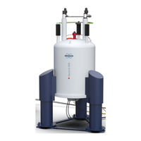
Bruker NMR MS 500 54 Ascend User Manual (98 pages)
Brand:
Bruker
| Category:
Industrial Equipment
| Size: 1 MB
Table of Contents
Table of Contents
3
Contact
7
1 Introduction
9
General Information
9
Limitation of Liability
9
Customer Service
9
Warranty
9
Copyright
9
General View
10
Figure 1.1: General View of a Magnet System with 2 Helium Turrets
10
2 Safety
11
Approved Persons
11
Customer Responsibilities
12
Key Words
13
Danger
13
Residual Risks
14
Persons
14
Intended Use
14
Safety Devices
15
Spare Parts
15
Signs and Labels
16
Technical Risks
16
Warning
17
Cryogenic Agents
17
Electricity
17
Gas under Pressure
18
Low Temperatures
19
Personal Protective Equipment
22
Description of Signs and Labels
23
Safety Devices
24
Figure 2.1: Safety Devices of the Cryostat with 2 Helium Turrets
24
Behavior in Danger and Emergency Situations
26
Fire Department Notification
26
3 Transportation
27
Safety
27
Packaging
27
Figure 3.1: Packaging (Without Surrounding Panels)
27
Disposal
28
Transport Inspection
28
Transportation by Fork Lift / Pallet Jack
29
Figure 3.2: Transportation by Forklift - Front Side
29
Figure 3.3: Transportation by Forklift - Rear Side
29
Transportation with a Crane
30
Figure 3.4: Attachment Points for Lifting Equipment
30
Figure 3.5: Instruction Label for Lifting Equipment
30
Storing
31
Disposal
31
4 Assembly
33
Safety
33
5 Operation
35
Safety
35
Magnetic Field
35
Persons
35
Set into Operation
36
Figure 5.1: Start the Magnet Stand
36
Figure 5.2: Stop the Magnet Stand
36
6 Troubleshooting
37
Safety
37
Spontaneous Ignition and Explosion
37
Problem
38
During Transportation
38
During Assembly
38
During Cooling Procedure
40
During Energizing and Shimming
44
During Operation of the Magnet Stand
47
During Standard Operation
49
During De-Energizing and Warming
51
Troubleshooting Work
52
After a Quench
52
Figure 6.1: Magnet System During a Quench
52
7 Maintenance
53
Safety
53
Cleaning
53
Maintenance Timetable
54
Maintenance-Free Components
54
Table 7.1: Maintenance Timetable
54
Table 7.2: Maintenance-Free Components of the Magnet System
54
8 Disassembly
55
Safety
55
9 Technical Data MS 400'54 Ascend
57
Environmental Conditions
57
Identification Plate
57
Table 9.1: Environmental Conditions
57
Dimensions
58
Weights
58
Dimensions for Transportation
58
Table 9.2: Weight of the Magnet System
58
Dimensions Cryostat
59
Figure 9.1: Dimensions of the Cryostat (Front View)
59
Table 9.4: Dimensions of the Cryostat - Front View
60
Figure 9.2: Dimensions of the Cryostat (Top View)
61
Table 9.5: Dimensions of the Cryostat - Top View
61
Safety Valves
62
Figure 9.3: Safety Valves of the Cryostat
62
Table 9.6: Opening Pressure of the Safety Valves of the Magnet System
62
Nitrogen Level Sensor
63
Figure 9.4: Nitrogen Level Sensor
63
Table 9.7: Nitrogen Level Sensor
63
Helium Level Sensor
64
Figure 9.5: Helium Level Sensor
64
Table 9.8: Helium Level Sensor
64
Temperature Sensors
65
Figure 9.6: Characteristic Curve of PT 100 Sensor
65
Table 9.9: Characteristic Values of PT 100 Sensor
65
Figure 9.7: Characteristic Curve of IBT Carbon Sensor
66
Table 9.10: Characteristic Values of IBT Carbon Sensor
66
Technical Data Magnet
67
Table 9.11: Specification of the Magnet
67
Fringe Field Plot
68
Figure 9.8: Fringe Field Plot of the Magnet System at Maximum Field
68
Table 9.12: Fringe Field Data of the Magnet System at Maximum Field
68
Filling Volume, Evaporation Rate and Hold Time
69
Table 9.13: Cryogenic Agents Consumption During Installation
69
Table 9.14: Cryogenic Agents
69
Nitrogen Level Graph
70
Figure 9.9: Nitrogen Level Graph
70
Helium Level Graph
71
Figure 9.10: Helium Level Graph
71
Resistance at Room Temperature
72
Table 9.15: Resistance at Room Temperature
72
Heater Currents
73
Shim Switch Heater
73
Table 9.16: Heater Currents
73
Table 9.17: Shim Switch Heater Operation
73
Energizing Assignment and Currents
74
Table 9.18: Energizing Assignment and Currents
74
Magnetic Center
75
Figure 9.11: Magnetic Center and Shimsystem Offset (SO)
75
Table 9.19: Magnetic Center
75
Cycling Assignment and Shim Currents
76
Table 9.20: Cycling Assignment and Shim Currents
76
Energizing Currents
77
Deenergizing Assignment and Currents
77
Table 9.21: Energizing Currents
77
Table 9.22: Deenergizing Assignment and Currents
77
Current Lead
79
Figure 9.12: Current Lead 55 Pin
79
Wiring Diagram Magnet
80
Figure 9.13: Wiring Diagram Magnet
80
Wiring Diagram Magnet Control and Shims
81
Figure 9.14: Wiring Diagram Magnet Control and Shims
81
Wiring Diagram Magnet Diagnostic and Temperature Sensors
82
Figure 9.15: Wiring Diagram Magnet Diagnostic and Temperature Sensors
82
Shorting Plug
83
Figure 9.16: Shorting Plug 55 Pins
83
Nitrogen Refill Report
84
Helium Refill Report
86
Appendix A
89
Warning Signs
89
List of Figures A.2 Figures
91
Figures
91
Tables
93
Glossary / Abbreviations
95
Advertisement
Advertisement
Related Products
Bruker Ascend MS 500'54
Bruker minispec
Bruker NMR MS 600'89 D359 Ascend DNP
Bruker NMR MS 300 54 Ascend ULH
Bruker NMR MS 400 89 Ascend DNP
Bruker NMR MS 600 89 Ascend DNP
Bruker MPA I
Bruker NMR 600'89 Ascend DNP
Bruker NMR 300 54 Ascend ULH
Bruker NMR 400 89 Ascend DNP
Bruker Categories
Laboratory Equipment
Measuring Instruments
Industrial Equipment
Security Sensors
Microscope
More Bruker Manuals
Login
Sign In
OR
Sign in with Facebook
Sign in with Google
Upload manual
Upload from disk
Upload from URL