Sign In
Upload
Manuals
Brands
BRP Manuals
Engine
Rotax 912 i Series
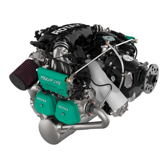
User Manuals: BRP Rotax 912 i Series Aircraft Engine
Manuals and User Guides for BRP Rotax 912 i Series Aircraft Engine. We have
2
BRP Rotax 912 i Series Aircraft Engine manuals available for free PDF download: Maintenance Manual
BRP Rotax 912 i Series Maintenance Manual (526 pages)
Brand:
BRP
| Category:
Engine
| Size: 56 MB
Table of Contents
List of Effective Pages
7
Table of Contents
21
General
22
Type Description
23
Abbreviations and Terms (Depending on Respective Engine Type)
24
Wiring Color Codes
29
Conversion Table
30
Safety Notice
31
Environmental Note
31
Safety Information
32
Instruction
34
Maintenance Concept
35
Technical Documentation
36
Use for Intended Purpose
38
Inspection of Parts and Report of Findings
39
Classification of Parts for Maintenance/Repair
41
Maintenance
44
Fastener Information
45
LOCTITE Application Procedure
46
Consumable Materials
51
Tools
55
Special Tools
61
Service Products
62
System Description
64
EMS Power Supply
64
Drive
64
Safety Instruction
64
Maintenance
64
General Information - Removal
64
Before the Internal Generator Is Removed
65
Measurement of Generator a and B
66
Removal
72
Ignition Housing - Removal
72
Sealing of the Plug Screws
74
Fly Wheel Assy. Removal
74
Stator Assy. - Removal
75
Inspection
79
Ignition Housing - Check
79
Bearing Bushing - Inspection
79
Stator Assy. and Flywheel Assy. - Inspection
80
Crankshaft Position Sensor (CPS_1/CPS_2) - Inspection
80
Oil Pressure Sensor (OPS) - Inspection
80
Wear Limits
81
Assembly
82
Ignition Housing - Assembly
82
Oil Seal Replacement
82
Oil Seal - Installation
82
Stator Assy. - Installation
83
Stator Connectors - Installation
84
Installation
88
Fly Wheel Assy. - Installation
88
Ignition Housing Assy. - Installation
88
Finishing Work
91
Tightening Torque
95
System Description
96
Drive
96
Safety Instruction
96
Maintenance
96
Before the External Alternator Is Removed
96
Removal
97
V-Belt Pulley - Removal
97
Alternator - Removal
97
Installation
99
V-Belt Pulley - Installation
99
Alternator - Installation
99
V-Belt Tension
101
Finishing Work
101
Special Tools
105
Service Products
106
System Description
108
Safety Instruction
108
Maintenance
108
Removal
109
Vacuum Pump - Removal
109
Inspection
112
Drive Sleeve - Inspection
112
Vacuum Pump Gear - Inspection
112
Vacuum Pump - Inspection
112
Installation
113
Oil Seal - Installation
113
Vacuum Pump Gear - Installation
113
Vacuum Pump - Installation
113
Finishing Work
114
Special Tools
119
Service Products
120
System Description
122
Safety Instruction
122
Maintenance
122
Removal
123
Governor - Removal
123
Governor Flange - Removal
123
Governor Drive - Removal
124
Inspection
126
Governor - Inspection
126
Governor Drive - Inspection
126
Wear Limits
128
Installation
129
Needle Sleeve - Installation
129
Ball Bearing - Installation
129
Roller Bearing Configuration 3 - Installation
130
Governor Drive - Installation
130
Governor Flange - Installation
130
Governor Installation
132
Finishing Work
133
Special Tools
137
Service Products
138
Installation Checklist
139
General Note
142
Delivery of the Engine
142
Engine Preservation
142
Return to Service
144
Treating Rust and Surface Damage
144
System Description
145
Description of Design
145
Technical Data
145
Operating Limits
145
Operating Fluids/Capacities
145
Weights
145
Serial and Part no
145
Serial Number
145
Part no
145
Engine/Components, General
146
Engine Components, Engine Views, Cylinder Designation and Definition of Main Axis
147
Maintenance
151
Power Plant
152
Safety Instruction
152
Power Plant - Removal
152
Removal of the Power Plant from the Aircraft
153
Power Plant - Installation
153
Trestle Adapter Assy. - Installation and Removal
155
Trestle Adapter Assy. - Removal
156
Finishing Work
157
Removal
158
Engine Suspension Frame - Removal
158
Inspection
160
Engine Suspension Frame - Inspection
160
Installation
161
Engine Suspension Frame - Installation
161
Finishing Work
161
System Description
165
Safety Instruction
165
Finishing Work
168
Wear Limits
170
Special Tools
173
Service Products
174
System Description
176
Safety Instructions
176
Maintenance
176
Removal
177
Disassembly
178
Disassembly of the Propeller Gearbox
178
Removal of the Propeller Shaft
179
Removal of the Ball Bearing
180
Blinding Shim - Removal
181
Removal of the Roller Bearing - Configuration 2
182
Removal of the Roller Bearing - Configuration 3
182
Inspection
184
Propeller Gearbox Single Parts - Inspection
184
Gear Cover Assy. - Inspection
184
Propeller Shaft - Inspection
185
Dog Hub - Inspection
186
Thrust Washer, Bearing Bushing - Inspection
187
Step Collar, Disc Spring - Inspection
187
Checking the Splines
188
Checking the Gear Set
188
Pitting, General Information
189
Slight Pitting
189
Destructive Pitting
190
Flake Pitting (Large-Area Flank Fractures)
191
Wear Limits
192
Propeller Gearbox
194
Assembly
196
Oil Spray Nozzle - Installation
196
Ball Bearing - Installation
196
Propeller Shaft - Installation
197
Adjustment of the Disc Spring Pretension
199
Assembly of the Propeller Gearbox Assy
200
Installation
201
Blinding Shim - Installation
201
Roller Bearing - Installation (Configuration 2)
201
Roller Bearing - Installation (Configuration 3)
201
Finishing Work
203
Special Tools
206
Service Products
207
General Note
209
Safety Instructions
209
Maintenance
209
Removal
210
Sprag Clutch - Removal
210
Sprag Clutch Housing - Removal
210
Disassembly
213
Disassembling the Sprag Clutch Housing
213
Inspection
214
Sprag Clutch Housing Single Parts - Inspection
214
Sprag Clutch Housing - Inspection
214
Sprag Clutch - Inspection
215
Free Wheel Gear - Inspection
215
Starter Idle Gear - Inspection
215
Assembly
216
Assembly of the Sprag Clutch Housing
216
Installation
217
Sprag Clutch Housing - Installation
217
Measuring the Axial Clearance of the Free Wheel Gear
218
Wear Limits
219
Finishing Work
220
Special Tools
224
Service Products
225
System Description
226
Safety Instruction
226
Maintenance
226
Removal
227
Surrounding Assemblies - Removal
227
Cylinder Head - Removal
229
Disassembly
231
Cylinder Head
231
Rocker Arm - Removal
231
Valve - Removal
231
Coolant Elbow Inlet - Removal
232
Oil Return Tubes - Removal
232
Coolant Elbow Outlet - Removal
232
Inspection
234
Cylinder Head Single Parts - Inspection
234
Cylinder Head Studs - Inspection
234
Cylinder Head Assy. - Inspection
234
Hardness Test Method
235
Valve Guide - Inspection
235
Valve - Inspection
236
Valve Seats - Inspection
237
Valve Spring - Inspection
238
Spring Force Measurement
238
Washer - Inspection
239
Rocker Arm and Rocker Arm Shaft - Inspection
240
Rocker Arm Bushing - Inspection
241
Push Rod - Inspection
241
Wear Limits
242
Assembly
247
Cylinder Head - Assembly
247
Oil Return Tube Installation
247
Coolant Elbow Inlet - Installation
247
Coolant Elbow Outlet - Assembly
248
Coolant Elbow - Installation
248
Valve Installation
249
Rocker Arm - Installation
250
Installation
251
Cylinder Head - Installation
251
Cylinder Head (Single) Repaired Per Engine Side
252
Cylinder Heads (Both) Repaired Per Engine Side
253
Valve Cover Installation
255
Finishing Work
255
Special Tools
259
Service Products
259
System Description
260
Safety Instruction
260
Maintenance
260
Removal
261
Cylinder and Piston - Removal
261
Hydraulic Valve Tappet - Removal
262
Inspection
264
Displacement Parts - Inspection
264
Piston - Inspection
264
Piston Rings - Inspection
265
Piston Pin - Inspection
266
Cylinder - Inspection
266
Hardness Test Method
267
Hydraulic Valve Tappet - Inspection
267
Wear Limits
268
Installation
274
Cylinder and Piston - Installation
274
Hydraulic Valve Tappet - Installation
274
Piston - Installation
274
Studs - Installation
277
Cylinder Installation
278
Finishing Work
278
Fuel System
279
System Description
281
Fuel Filter
281
Safety Instruction
281
Special Tools
285
Service Products
286
System Description
289
Fuel Pump Module
289
Fuel Distribution
289
Safety Instruction
290
Maintenance
290
Removal
291
Environmental Note
291
Fuel Pressure Regulator - Disassembly
291
Fuel Pressure Regulator Assy. - Removal
292
Fuel Line Assy. - Removal
293
Fuel Rail - Removal
294
Fuel Rail - Disassembly
296
Throttle Body Assy. - Removal
297
Intake Manifold - Removal
298
Airbox - Removal
300
Fuel Pump Assy. - Removal
301
Inspection
303
Fuel Line Assy. - Inspection
303
Fuel Pressure Regulator Assy. - Inspection
303
Pressure Regulator Housing - Inspection
304
Fuel Rail - Inspection
304
Fuel Injector - Inspection
304
Intake Manifold - Inspection
305
Connecting Socket - Inspection
306
Airbox - Inspection
306
Throttle Body - Inspection
306
Fuel Pump Assy. Single Parts - Check
307
Fuel Pump - Inspection
307
Air Filter - Inspection
308
Fuel Filter - Inspection
308
Assembly
311
Fuel Pump Assy. Single Parts - Assembly
311
Fuel Pump Assy. - Assembly
313
Fuel Pressure Regulator - Assembly
313
Airbox - Assembly
315
Installation
316
Fuel Pump - Installation
316
Airbox - Installation
316
Intake Manifold - Installation
316
Fuel Rail - Installation
317
Fuel Pressure Regulator Assy. - Installation
319
Fuel Line Assy. - Installation
321
Throttle Body Assy Installation
322
Finishing Work
323
Ignition Unit
325
System Description
328
Service Products
331
System Description
332
Internal Generators
332
Double Ignition Coils
332
Ignition Cable Assy
332
Spark Plugs
332
Wiring Harness
333
Fuse Box
333
Crankshaft Position Sensor (CPS)
333
Safety Information
333
Removal
334
Internal Generator - Removal
334
Spark Plug Connector and Ignition Cable Assy. - Removal
334
Double Ignition Coil - Removal
335
Spark Plug - Removal
337
Knock Sensor - Removal
337
Inspection
338
Double Ignition Coil Assy. and Ignition Cable Assy. - Inspection
338
Spark Plug Connector - Inspection
339
Spark Plug - Inspection
339
Knock Sensor (Knock) - Inspection
339
Installation
340
Knock Sensor - Installation
340
Spark Plug - Installation
340
Spark Plug Connector and Ignition Cable Assy. - Installation
340
Double Ignition Coil (Screwed Connection) - Installation
341
Double Ignition Coil (Plugged Connection) - Installation
343
Internal Generator - Installation
346
Finishing Work
346
Special Tools
349
Service Products
350
System Description
353
Coolant
353
Radiator
353
Water Pump
353
Expansion Tank
353
Overflow Bottle
353
Safety Information
353
Connections for Display Systems
353
Coolant Temperature Sensor (CTS)
354
Maintenance
354
Removal
355
Environmental Note
355
Surrounding Assemblies - Removal
355
Expansion Tank with Upper Form Hoses - Removal
357
Cooling Air Baffle - Removal
358
Water Pump Housing with Lower Form Hoses - Removal
358
Disassembly
361
Ignition Housing - Disassembly
361
Water Pump Shaft - Removal
361
Oil Seal and Rotary Seal - Removal
361
Form Hoses - Removal
361
Water Pump Housing - Disassembly
362
Inspection
363
Cooling System Single Parts - Inspection
363
Axial Position of Water Pump Shaft Inspection
363
Expansion Tank - Inspection
363
Water Pump Housing - Inspection
364
Wear Limits
365
Assembly
366
Ignition Housing - Assembly
366
Water Pump Housing - Assembly
367
Form Hose - Installation
368
Installation
372
Ignition Housing - Installation
372
Water Pump Housing with Lower Form Hoses - Installation
372
Cooling Air Baffle - Installation
374
Expansion Tank and Form Hoses - Installation
374
Surrounding Assemblies - Installation
375
Finishing Work
376
Engine Control
379
Special Tools
382
System Description
384
General Note
384
Safety Instruction
384
Maintenance
384
Technical Data
385
Ecu Removal
387
Ecu - Inspection
388
Ecu Installation
389
Ecu - Read out and Flashing
390
Ecu on Workbench
391
Identify Current Ecu Configuration
391
Read out Log Files
393
Software Update
394
Ecu Installed in Aircraft
396
Finishing Work
396
System Description
399
General Note
399
Safety Instruction
399
Maintenance
399
Fuse Box - Removal
401
Regulator B - Removal
401
Regulator a - Removal
404
Installation
406
Regulator B - Installation
407
Regulator a - Installation
410
Cover - Installation
414
Fuse Box - Installation
415
Finishing Work
416
Inspection of the Fuse Box Installation
416
Special Tools
420
System Description
423
Safety Instruction
423
Maintenance
423
Starter Relay - Disconnection
424
Ambient Air Pressure and Temperature Sensor - Disconnection
425
Fuel Pump - Disconnection
426
Oil Temperature Sensor and Oil Pressure Sensor - Disconnection
429
Wiring Harness Removal
433
Installation
435
Wiring Harness - Installation
436
Service Products
446
System Description
449
Actuators and Indicators
449
Maintenance
450
Oil Pressure Sensor (Ops) - Removal
452
Oil Temperature Sensor (Ots) - Removal
454
Throttle Potentiometer (Tps) - Removal
457
Double Ignition Coil - Removal
458
Sensors and Actuators
459
General Resistance Measurement
459
General Test Procedure
459
Resistance Measurement
460
Voltage Measurement
460
Current Measurement
461
Oil Temperature Sensor (Ots) - Inspection
463
Knock Sensor (Knock) - Inspection
465
Double Ignition Coil - Inspection
468
Installation
470
Oil Pressure Sensor (Ops) - Installation
470
Oil Temperature Sensor (Ots) - Installation
472
Knock Sensor (Knock) - Installation
474
Throttle Potentiometer (Tps) - Installation
476
Double Ignition Coil - Installation
476
Finishing Work
477
Exhaust System
479
Exhaust Pipe Removal
487
Exhaust Assy. - Inspection
488
Exhaust Pipe and Cylinder Head - Inspection
488
Finishing Work
490
Oil Pump
497
Oil Pump Assy. Removal
497
Oil Pump - Disassembly
498
Oil Pump Housing - Inspection
500
Rotary Piston/Rotor - Inspection
501
Oil Pump Shaft - Inspection
501
Oil Pressure Regulator - Inspection
501
Oil Pump - Assembly
503
Oil Pump Installation
505
Oil Pump Housing O-Rings
505
Oil Filter - Installation
506
Oil Tank - Disassembly
508
Oil Tank - Assembly
509
Oil Tank - Installation
510
Oil Lines
511
Electric Starter
513
Electric Starter - Removal
517
Electric Starter Inspection
517
Electric Starter - Installation
518
Advertisement
BRP Rotax 912 i Series Maintenance Manual (186 pages)
Brand:
BRP
| Category:
Engine
| Size: 36 MB
Table of Contents
Brp-Rotax Maintenance Manual Line Chapter: 00-00-00 General Note
15
Table of Contents
15
General
16
Abbreviations and Terms (Depending on Respective Engine Type)
17
Wiring Color Codes
22
Conversion Table
23
Safety Notice
24
Safety Information
25
Instruction
27
Maintenance Concept
28
Technical Documentation
29
Use for Intended Purpose
31
Brp-Rotax Maintenance Manual Line Chapter: 05-00-00 Maintenance
35
General Note
36
Authorized Personnel
38
Procedure Notes
39
Troubleshooting
41
Consumable Materials
42
Acceptable Methods, Techniques and Practice
46
Brp-Rotax Maintenance Manual Line Chapter: 05-10-00 Time Limits
49
Definition of Terms
50
Operating Hours
50
Terminology
50
General Overhaul (TBO)
51
Life Cycle
51
Purging the Oil System
51
Time Limit
51
Time Limit
52
Annual Inspection
54
Time Limit for Parts
54
Time Limit for the Coolant
54
Brp-Rotax Maintenance Manual Line Chapter: 05-20-00 Scheduled Maintenance Checks
55
Scheduled Maintenance Checks
56
Unscheduled Maintenance Checks
57
Visual Inspection
59
Maintenance Schedule Procedures (Maintenance Check List)
60
Check List/Maintenance Schedule
61
Maintenance Schedule
63
Brp-Rotax Maintenance Manual Line Chapter: 05-50-00 Unscheduled Maintenance Checks
71
Engine Check after Propeller Strike Incidents
72
Removal of the Propeller Gearbox
72
Drive Gear - Removal
75
Propeller Strike Inspection
76
Installation of Propeller Gearbox
81
Checking of the Overload Clutch
85
Examination after Engine Failure
88
Returning Engine to Service after Submerging in Water
89
Diminished Functional Capability of EMS
91
Inspection in Extreme Climatic Conditions
91
Returning Engine to Service after Influence by Fire
91
Exceeding of Max. Admissible Engine RPM
92
Exceeding of Max. Coolant Temperature
94
Non Compliance with the Coolant Specification
96
Checking of the Cooling System / Radiator Cap
97
Exceeding the Max. Permissible Oil Temperature
104
Oil Pressure below Minimum Value
106
Oil Specification Not Respected
108
Non Compliance of Fuel Quality
110
Spark Plug Not in Accordance with Specification
110
Smooth Performance of the Engine
111
Lightning Strike
112
Reporting
113
Brp-Rotax Maintenance Manual Line Chapter: 12-10-00 Replenishing Operating Fluids
117
Servicing Points on the Engine
118
Fluid Capacities
119
Coolant Check/Replenish
120
Cooling System
120
Lubrication System
123
Oil Level Check/Replenish
123
Brp-Rotax Maintenance Manual Line Chapter: 12-20-00 Scheduled Maintenance
127
Engine Cleaning
129
Checking the Engine Suspension
130
Corrosion
130
Visual Inspection
130
Leakage Check
131
Differential Pressure Check
133
Compression Check for Fault-Tracing
137
Checking ECU
139
Engine Control Unit (ECU)
139
Read out the ECU Data Memory
139
Locking/Loosening of the Crankshaft
141
Test Run of Engine
143
Checking the V-Belt Tension
145
Belt Tension Adjustment
146
Air Intake System
147
Checking Air Intake System
148
Cleaning the Dry Air Filter
148
Replacing the Dry Air Filter
150
Cooling System
151
Checking the Cooling System
152
Replacing the Coolant
153
Flushing the Cooling System
155
Expansion Tank, Radiator Cap
156
Accessories (Including Radiator, Radiator Hoses, Hose Clamps, Cooling Air Ducts)
157
Overflow Bottle
157
Fuel System
158
Checking the Fuel Lines
159
Checking the Fuel Pressure Regulator
159
Leak Tests
159
Check Valves
160
Fuel Injectors
160
Fuel Pumps
160
Fuel Rail
160
Lubrication
161
Oil Change
163
Oil Filter Removing
164
Inspecting of the Oil Filter Components
166
Installing New Oil Filter
168
Cleaning the Oil Tank
169
Flushing the Oil Circuit
171
Purging the Oil System
171
Inspecting the Magnetic Plug
173
Installation of the Magnetic Plug
174
Electric System
175
Check of Wiring
176
Inspection of Spark Plugs
177
Remove the Spark Plugs
177
Replacement of Spark Plugs
177
Installation of Spark Plug
179
Fuse Box
180
Checking the Propeller Gearbox
181
Propeller Gearbox
181
Advertisement
Related Products
BRP ROTAX 912 Series
BRP ROTAX 912 A
BRP ROTAX 912 F
BRP ROTAX 912 S
BRP ROTAX 912 UL
BRP ROTAX 912 ULS
BRP ROTAX 912 ULSFR
BRP Rotax 912 S/ULS
BRP ROTAX 916 iSc A
BRP ROTAX 914 F
BRP Categories
Offroad Vehicle
Engine
Snowmobiles
Outboard Motor
Boat
More BRP Manuals
Login
Sign In
OR
Sign in with Facebook
Sign in with Google
Upload manual
Upload from disk
Upload from URL