Sign In
Upload
Manuals
Brands
Brooks Manuals
Measuring Instruments
MT3810G
Brooks MT3810G Manuals
Manuals and User Guides for Brooks MT3810G. We have
2
Brooks MT3810G manuals available for free PDF download: Installation And Operation Manual, Installation & Operation Manual
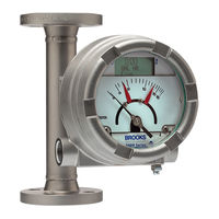
Brooks MT3810G Installation And Operation Manual (93 pages)
Metal Tube Variable Area Flowmeters
Brand:
Brooks
| Category:
Measuring Instruments
| Size: 10 MB
Table of Contents
Table of Contents
4
1 Introduction
7
Design Features
7
Overview of Meter Specifications
7
B ELF Body/Float Stop/Float/Metering Tube Material Restrictions
8
1-1B ELF Body/Float Stop/Float/Metering Tube Material Restrictions
9
1-1A Meter Specifications
9
Number
9
Flow Capacities, Pressure Drop and Viscosity Immunity Ceiling Values
9
Pressure Ratings
10
Model MT3809/MT3810 Pressure Ratings, Flanged
10
Model MT3809/MT3810 Pressure Ratings, NPT Female
11
Model MT3809/MT3810 Pressure Ratings, NPT Male
12
Temperature Ratings
13
Outline and Dimensions
13
Model MT3809 and MT3810 Dimensional Drawings (MM/In) and Weights (Kg/Lbs) - General Purpose Housing
14
Model MT3809 and MT3810 Dimensional Drawings (MM/In) and Weights (Kg/Lbs) - Intrinsically Safe Housing
15
Model MT3809 and MT3810 Dimensional Drawings (MM/In) and Weights (Kg/Lbs) - Explosion Proof Housing
16
Optional Valves and Flow Controllers
17
Optional Electronic Features
17
Inductive Alarms
17
1-6 Temperature Cut-Off Tables
18
Current Loop 4-20 Ma with HART Transmitter, with Alarms, Display and Pulse Output
18
Ma with HART Transmitter Description Table
18
F Fieldbus Transmitter Description Table
19
1-8 Foundationfieldbus Transmitter Description Table
20
1-7-2 Foundation Fieldbus Transmitter, with Alarms and Pulse Output
20
Inductive Alarms
20
Inductive Alarms Description Table
20
Product Approvals Overview
21
Product Approvals
21
Pro
24
Pro Cess and Ambient Temperature Limits
24
Cess and Ambient Temperature Limits
26
Electrical Data: Intrinsic Safety
26
Electrical Entries
27
General
28
Receipt of Equipment
28
Recommended Storage Practices
28
Return Shipment
28
Installation of Flowmeter
29
Typical Bypass Installation
30
How to Remove and Reinstall GP Housing Indicator Covers
31
How to Remove and Reinstall IS Housing Indicator Covers
32
How to Remove and Reinstall XP Housing Indicator Covers
33
Electrical Connections to MT3809 with 4-20 Ma/Hart Transmitter, Alarms and Pulse Output
34
Power Supply Vs. Maximum Load Resistance
34
Mechanical Indicator Zero
36
Transmitter Indicator Zero
37
Ma/Hart Transmitter Intrinsically Safe Installation
38
B Wiring Diagram, Model MT3809, Transmitter 4-20 Ma (Continued)
39
A Wiring Diagram, Model MT3809, 4-20 Ma Transmitter, One or Two Optical Alarms and PPU
40
B Wiring Diagram, Model MT3809, 4-20 Ma Transmitter, One or Two Optical Alarms and PPU (Continued)
41
A Wiring Diagram, Model MT3809, One or Two Inductive Alarms
42
B Wiring Diagram, Model MT3809, One or Two Inductive Alarms (Continued)
43
A Wiring Diagram, Model MT3809, 4-20 Ma Transmitter, One or Two Inductive Alarms
44
Ma/Hart Transmitter Division 2 Installation
46
Ma/Hart Transmitter Flameproof Installation
46
2-18
47
2-8B Wiring Diagram, Model MT3809, 4-20 Ma Transmitter, One or Two Inductive Alarms (Continued)
47
2-8A Wiring Diagram, Model MT3809, 4-20 Ma Transmitter, One or Two Inductive Alarms
47
Wiring Diagram, Model MT3809 Explosion Proof with Transmitter And/Or Inductive Alarm
47
Electrical Connection to MT3809 with F Oundation Fieldbus Transmitter, Alarms and Pulse Output
48
Mechanical Indicator Zero
49
F Fieldbus Transmitter Indicator Zero
50
2-21
51
F Oundation Fieldbus Transmitter Intrinsically Safe Installation
51
2-11 Foundation Fieldbus Transmitter Indicator Zero
52
Wiring Diagram, Model MT3809, F
52
Installation of the Model MT3809 Flowmeter with Inductive Alarms (1 or 2 Switches)
56
3 Operation
58
Start-Up and Operation of Flowmeter
58
Operation of the Model MT3809 Flowmeter with a Transmitter with or Without Optional Alarms and Pulse Output for Totalization
59
2-15 Wiring Diagram, Model MT3809, F Oundation Fieldbus - Entity Concept - Transmitter
60
Communication with HART Transmitter Using Device Descriptor
60
Model MT3809 Electronics Basic Setup Menu Tree
60
Model MT3809 Electronics Detailed Setup Menu Tree
61
Communication with F Oundation Fieldbus Transmitter
63
Communication with Transmitter Using Local Operator Interface with LCD Display
63
Adjusting Inductive Alarms (1 or 2 Switches)
63
Simulate
63
Transmitter "Simulate" Connection
63
Model MT3809 Electronics LOI Chart Menu
64
General Service Information
65
Meter Float Cleaning (MT3809 & MT3810)
66
Exploded View, Model MT3809G and MT3810G - Gas Service
69
Exploded View, Model MT3809G and MT3810G - Liquid Service
70
Meter Float Cleaning (MT3809 ETFE Option)
71
Meter Indicator Reference Mark (Zero) Adjustment
71
Transmitter Replacement with or Without Alarms and Pulse Output
71
Inductive Alarm Replacement
72
Transmitter Replacement with Inductive Alarms
72
Digital Display Replacement
72
Advertisement
Brooks MT3810G Installation & Operation Manual (72 pages)
Metal Tube Variable Area Flowmeters
Brand:
Brooks
| Category:
Measuring Instruments
| Size: 9 MB
Table of Contents
Table of Contents
3
Introduction
6
Design Features
6
Pressure Ratings
9
1-4 Temperature Ratings
12
Outline and Dimensions
12
Optional Valves and Flow Controllers
16
Optional Electronic Features
16
Current Loop 4-20 Ma with HART Transmitter, with Alarms, Display and Pulse Output
17
FOUNDATION TM Fieldbus Transmitter, with Alarms and Pulse Output
18
Inductive Alarms
19
Product Approvals Overview
20
General
27
Receipt of Equipment
27
Recommended Storage Practices
27
Return Shipment
27
Installation of Flowmeter
28
How to Remove and Reinstall GP Housing Indicator Covers
30
How to Remove and Reinstall IS Housing Indicator Covers
31
How to Remove and Reinstall XP Housing Indicator Covers
32
Electrical Connections to MT3809 with 4-20 Ma/Hart Transmitter, Alarms and Pulse Output
33
4-20 Ma/Hart Transmitter Intrinsically Safe Installation
37
4-20 Ma/Hart Transmitter Division 2 Installation
45
4-20 Ma/Hart Transmitter Flameproof Installation
45
Oundation
47
FOUNDATION Fieldbus Transmitter Intrinsically Safe Installation
50
Installation of the Model MT3809 Flowmeter with Inductive Alarms (1 or 2 Switches)
55
Operation
57
Start-Up and Operation of Flowmeter
57
Operation of the Model MT3809 Flowmeter with a Transmitter with or Without Optional Alarms and Pulse Output for Totalization
58
Communication with HART Transmitter Using Device Descriptor
59
Communication with FOUNDATION Fieldbus Transmitter
62
Communication with Transmitter Using Local Operator Interface with LCD Display
62
Adjusting Inductive Alarms (1 or 2 Switches)
62
Simulate
62
General Service Information
64
Meter Float Cleaning (MT3809 & MT3810)
65
Meter Float Cleaning (MT3809 ETFE Option)
70
Meter Indicator Reference Mark (Zero) Adjustment
70
Transmitter Replacement with or Without Alarms and Pulse Output
70
Inductive Alarm Replacement
71
Transmitter Replacement with Inductive Alarms
71
Digital Display Replacement
71
Advertisement
Related Products
Brooks MT3809G Metal Tube
Brooks Ar-Mite MT3750C
Brooks MT 3809
Brooks MT 3819
Brooks MT3809 ELF
Brooks MT3810
Brooks MT3809G TFE Lined
Brooks MT3809 TFE Lined
Brooks Ar-Mite MT3750
Brooks MF50 S
Brooks Categories
Measuring Instruments
Controller
Laboratory Equipment
Security System
Robotics
More Brooks Manuals
Login
Sign In
OR
Sign in with Facebook
Sign in with Google
Upload manual
Upload from disk
Upload from URL