Sign In
Upload
Manuals
Brands
Bosch Manuals
Control Panel
Rexroth IndraControl VCP 25
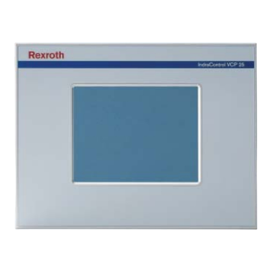
Bosch Rexroth IndraControl VCP 25 Manuals
Manuals and User Guides for Bosch Rexroth IndraControl VCP 25. We have
1
Bosch Rexroth IndraControl VCP 25 manual available for free PDF download: Project Planning Manual
Bosch Rexroth IndraControl VCP 25 Project Planning Manual (82 pages)
Brand:
Bosch
| Category:
Control Panel
| Size: 2.93 MB
Table of Contents
Table of Contents
3
Fig. 1-1: VCP 25 with Touch Screen
7
System Presentation
7
Brief Description of the VCP 25
7
Commissioning
8
Operating System
8
Important Directions for Use
9
Appropriate Use
9
Introduction
9
Areas of Use and Application
10
Inappropriate Use
10
Fig. 3-1: Hazard Classification (According to ANSI Z535)
11
Safety Instructions for Electric Drives and Controls
11
Explanations
11
Introduction
11
Hazards by Improper Use
12
General Information
12
Protection against Contact with Electrical Parts
14
Protection against Electric Shock by Protective Low Voltage (PELV)
15
Protection against Dangerous Movements
16
Protection against Contact with Hot Parts
18
Protection against Magnetic and Electromagnetic Fields During Operation and Mounting
18
Protection During Handling and Mounting
19
Battery Safety
19
Protection against Pressurized Systems
20
Technical Data
21
Front Panel and Housing
21
Touch Screen and Display
21
Electrical Data
22
Central Processing Unit and Memory
23
Interfaces
23
Connection System
24
Ambient Conditions
24
Standards and Guidelines
24
Compatibility Test
25
Dimensions
27
Installation
27
Front Panel Dimensions
28
Fig. 5-1: Front Panel Dimensions
28
Fig. 5-2: Mounting Cutout
29
Mounting Cutout
29
Standard Device
30
Fig. 5-3: Side View and Mounting Depth for the Standard Device
30
Side View, Mounting Depth
30
Field Bus Device
31
Fig. 5-4: Side View and Mounting Depth for the Field Bus Device
31
Setting the Contrast / Brightness
33
Fig. 6-1: Values for the Representation Type
33
Display
33
Display and Operating Components
33
Default Contrast / Default Brightness Setting
34
Character Attributes
34
Fonts
34
Touch Screen
35
Reset Key
35
User Mode Switch
35
Fig. 6-2: User Mode Switch
35
Interfaces
37
Fig. 7-1: Device Variants
37
Fig. 7-2: Rear View of Standard Device
38
Standard Interfaces
38
TTY / 20 Ma Current Loop (X3-SER1)
40
Pin Assignment
40
Fig. 7-3: 25 Pin D-SUB Female Connector Strip
40
Fig. 7-4: Pin Assignment TTY / 20 Ma, Passive
40
Termination
41
Fig. 7-5: Pin Assignment TTY / 20 Ma, Active
41
Fig. 7-7: Pin Assignment RS485
42
Fig. 7-6: 25 Pin D-SUB Female Connector Strip
42
Termination
42
Pin Assignment
42
Rs485 (X3-Ser1)
42
Fig. 7-8: Block Diagram Termination RS485
43
Fig. 7-9: Resistance Values Termination RS485
43
Fig. 7-10: Termination Switch
43
Rs232C (X3-SER1)
44
Pin Assignment
44
Termination
44
Fig. 7-11: 25 Pin D-SUB Female Connector Strip
44
Fig. 7-12: Pin Assignment Rs232C
44
Fig. 7-14: Pin Assignment of the Rs232C Interface
45
Rs232C (X3-SER2)
45
Fig. 7-13: 25-Pin D-SUB Female Connector Strip
45
Pin Assignment
45
Field Bus Interfaces
46
Devicenet
46
Fig. 7-15: Rear View Devicenet
46
Pin Assignment
48
Cable
48
Fig. 7-16: 9-Pin D-SUB Male and Female Connector Strip
48
Fig. 7-17: Pin Assignment Devicenet
48
Fig. 7-18: Data Line Devicenet
48
Termination
49
Diagnostics
49
Fig. 7-19: Baud Rate Devicenet
49
Fig. 7-20: Arrangement of the Devicenet Diagnostics LED
49
Fig. 7-21: Function of the Devicenet Diagnostics LED
49
Interbus
50
Fig. 7-22: Rear View INTERBUS
50
Fig. 7-25: Pin Assignment INTERBUS
52
Fig. 7-24: Pin Assignment INTERBUS
52
Fig. 7-23: 9-Pin D-SUB Male and Female Connector Strip
52
Pin Assignment
52
Cable
53
Diagnostics
53
Fig. 7-26: Arrangement of the INTERBUS Diagnostics Leds
53
Fig. 7-27: Functions of the INTERBUS Diagnostics Leds
53
Profibus Dp
54
Fig. 7-28: Rear View PROFIBUS DP
54
Fig. 7-30: Pin Assignment PROFIBUS DP
56
Cable
56
Fig. 7-29: 9-Pin D-SUB Female Connector Strip
56
Pin Assignment
56
Termination
57
Diagnostics
57
Fig. 7-31: Baud Rate PROFIBUS DP
57
Fig. 7-32: Arrangement of the PROFIBUS DP Diagnostic LED
57
Fig. 7-33: Function of the PROFIBUS-DP Diagnostic LED
57
Fig. 7-34: Rear View of the Memory Card
58
Fig. 7-35: Inserting the Memory Card
58
Inserting the Memory Card
58
Memory Card (Option)
58
Ejecting the Memory Card
59
Shielding D-SUB Connectors
59
Fig. 7-36: Ejecting the Memory Card
59
Fig. 7-37: Shielding D-SUB Connectors
59
Unpacking the Device
61
Data Backup
61
Exchange of Hardware Components
61
General Information
61
Maintenance and Installation
61
Identification
62
Fig. 8-1: Nameplate (Example)
62
Connecting
63
Supply Voltage 24 V
63
Fig. 8-2: Pin Assignment Supply Voltage
63
Fig. 8-3: Preparing the Cable
64
Fig. 8-4: Connecting the Female Connector Strip
64
Fig. 8-5: Female Connector Strip Is Plugged on
65
Fuse
65
Front Panel
65
Battery
66
Changing the Battery
66
Fig. 8-6: Screws on the Standard Device (Left) / Field Bus Device
66
Battery Disposal
67
Ordering Information
69
Type Code
69
Accessories
70
List of Figures
71
Index
73
Helpdesk
75
Internet
75
Service & Support
75
Service-Hotline
75
Deutschland - Germany
76
Kundenbetreuungsstellen - Sales & Service Facilities
76
Vor der Kontaktaufnahme
76
Europa (West) - Europe (West)
77
Europa (Ost) - Europe (East)
78
Afrika, Asien, Australien (Inkl. Pazifischer Raum) - Africa, Asia, Australia (Incl. Pacific Rim)
79
Nordamerika - North America
80
Südamerika - South America
80
Advertisement
Advertisement
Related Products
Bosch Rexroth IndraControl VCP 05
Bosch Rexroth IndraControl VCP 20
Bosch REXROTH IndraControl VAM 12.1
Bosch Rexroth IndraControl VR 21 Series
Bosch Rexroth IndraControl VR2107 Singletouch
Bosch Rexroth IndraControl VR2109 Singletouch
Bosch Rexroth VAM 10.2
Bosch Rexroth VAM 40.2
Bosch Rexroth VAM 10.1
Bosch Rexroth IndraControl VAM 11.1
Bosch Categories
Dishwasher
Washer
Oven
Power Tool
Dryer
More Bosch Manuals
Login
Sign In
OR
Sign in with Facebook
Sign in with Google
Upload manual
Upload from disk
Upload from URL