Sign In
Upload
Manuals
Brands
BK Vibro Manuals
Monitor
VIBROCONTROL 6000
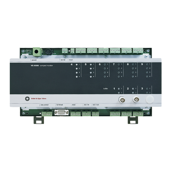
User Manuals: BK Vibro VIBROCONTROL 6000 Monitor
Manuals and User Guides for BK Vibro VIBROCONTROL 6000 Monitor. We have
1
BK Vibro VIBROCONTROL 6000 Monitor manual available for free PDF download: Technical Documentation Manual
BK Vibro VIBROCONTROL 6000 Technical Documentation Manual (233 pages)
Compact monitor
Brand:
BK Vibro
| Category:
Monitor
| Size: 6 MB
Table of Contents
Table of Contents
11
Safety Advice
13
2 What Is a VIBROCONTROL 6000 Compact Monitor
14
3 Structure of this Documentation
15
4 The Name Plate
16
5 The Signal-Flow Chart
17
6 Parameter Configuration Sheet
19
7 The Configuration Sheet
21
Plug to Socket Position Arrangement (in the Example)
22
8 System Reliability
23
Technical Data
25
OK-Monitoring Function
26
Channel Over-Ranging Identification Function
27
Instrument Conduct after a Power Failure
30
Significance of the Logbook
31
9 Mounting and Installation
32
Site Conditions
33
Mounting the Instrument
35
Wiring and Connection of Sensors
36
Wiring and Connection of Peripheral Equipment
39
System Connections
41
Commissioning and Function Testing
44
Function Testing
45
10 Digital Communication
46
11 Typical Measurement Tasks
47
Rolling-Element Bearing Condition Unit – BCU
48
Relative Shaft Vibration Acc. to DIN ISO 7919
49
Process Value
50
Vector
51
12 Contents Index for the Following Documentation
52
Ac Power Supply
72
System Function
73
Electrical Data
94
Contents - Components
101
Sensor Block
107
Function
107
Parameters and Setting Ranges
107
Parameter List
107
Summary of the Parameters
110
Sensor-(A/B) Block
111
Function
111
Parameters and Setting Ranges for GP-TIM
111
Parameter List
111
Summary of the Parameters for GP-TIM
113
Parameters and Setting Ranges for BCU-CON
113
Parameter List
113
Summary of Parameters for BCU-CON
114
Binary-Input Block
115
Function
115
Parameters and Setting Ranges
115
Parameter List
115
Summary of the Parameters
117
Highpass / Lowpass Filter
118
Function
118
Parameter List with Setting Ranges
118
Bandpass Filter Acc. to DIN ISO
119
Highpass Filter Acc. to DIN ISO
119
Bandpass Filter for Rolling-Element Bearing Condition
120
Lowpass Filter for Rolling-Element Bearing Condition
120
Highpass Filter for Rolling-Element Bearing Condition
120
Lowpass Filter Acc. to DIN ISO
119
Variable Bandpass Filter
120
Variable Lowpass Filter
120
Variable Highpass Filter
121
Analogue Signal Integration
122
Frequency Response Linearisation
122
Summary of Parameters for Signal Filtering
122
Function
123
Parameter List
123
Parameters and Setting Ranges
123
Trigger Block
123
Summary of the Parameters
124
BCU Measurement
125
Function
125
Parameters and Setting Ranges
125
Summary of the Parameters
126
DC Measurement
127
Function
127
Parameters and Setting Ranges
127
Summary of the Parameters
128
Speed Measurement
129
Function
129
Parameter List
130
Parameters and Setting Ranges
130
Summary of the Parameters
131
Vibration Measurement
132
Function
132
Display Parameters
133
Configuration Parameters
133
Parameters and Setting Ranges
133
Parameter Summary
135
Function
136
Parameters and Their Setting Ranges
136
Peak Measurement
136
Summary of the Parameters
137
Function
138
Peak-Peak Measurement
138
Parameter List
139
Parameters and Setting Ranges
139
Summary of the Parameters
139
Cyclic Peak-Peak Measurement
140
Display Parameters
140
Function
140
Parameters and Setup Ranges
140
Configuration Parameters
141
Parameter Summary
142
Function
143
RMS Measurement
143
Parameters and Their Setting Ranges
144
Summary of the Parameters
144
14 S Max Measurement
145
Function
145
Parameters and Their Setting Ranges
145
Summary of the Parameters
146
Display Parameters
147
Function
147
Max-Hold
147
Parameters and Setup Ranges
147
Configuration Parameters
148
Function
148
MIN-HOLD Measurement
148
Parameter Summary
148
Configuration Parameters
149
Display Parameters
149
Parameter Summary
149
Parameters and Setup Ranges
149
Function
150
Parameter List
150
Parameters and Setting Ranges
150
Vector Measurement
150
Summary of the Parameters
153
Centre Frequency, Bandwidth and Required Measuring Time
154
Cycle-DC Measurement
155
Function
155
Parameter List
157
Parameters and Setting Ranges
157
Summary of the Parameters
159
Calculated Scalar Values
160
General
160
Crest Factor
161
Max (X,Y) Peak-Peak
161
Peak Calculated
161
Peak-Peak Calculated
161
Function
162
Monitor (Absolute) Block
162
Parameter List
162
Parameters and Their Setting Ranges
162
Summary of the Parameters
164
Dual-Monitor (2 Absolute Limit Values) Function
165
Parameter List
165
Parameters and Setting Ranges
165
Summary of the Parameters
169
Function
170
Logic Block for Relay Control
170
OR-Link
170
Typical Variants of the Logic Block
170
2-Of-3 Logic
171
AND-Link
171
2-Of-4 Logic
172
3-Of-4 Logic
173
Logic Block Status Display
173
DC Output
174
Function
174
Parameter List
174
Parameters and Their Setting Ranges
174
Summary of the Parameters
178
Function
179
Parameters and Their Setting Ranges
179
Relay Block
179
Summary of the Parameters
181
COM Block
182
Function
182
Parameter List
183
The Display
193
User Menus
197
Selecting the Language
198
Reset All
199
Editing Parameters
207
Parameters and Their Setting Ranges
183
Advertisement
Advertisement
Related Products
BK Vibro Categories
Monitor
Cables and connectors
More BK Vibro Manuals
Login
Sign In
OR
Sign in with Facebook
Sign in with Google
Upload manual
Upload from disk
Upload from URL