
Summary of Contents for BK Vibro VIBROCONTROL 6000
- Page 1 B & K s.r.o. Palisády 20, 811 06 Bratislava Slovak Republic 02/ 544 307 01 bk@bruel.sk, www.bruel.sk...
- Page 3 Individuelle Gerätedokumentation Individual instrument documentation Documentation individuelle de l’appareil Einführung Introduction Introduction Module – Technische Daten Modules – Technical Data Modules – Caractéristiques techniques Komponenten des Signalflussgraphen Components of the signal flow chart Componentes de signaux flux Dialog mit dem User Terminal Dialog with the User Terminal Fenêtre de dialogue Terminal Utilisateur...
- Page 7 VC-6000 Compact monitor User Terminal Superuser Passwort Passwortgeschützter Menüzugriff Das Menüsystem zum VC-6000 Compact monitor ist mit einem Passwortschutz ausgestattet. Es gibt zwei Sicherheitsstufen: USER und SUPERUSER. Ohne Passworteingabe wird der Benutzer als USER eingeordnet. Ein User kann nur lesend auf das Menüsystem zugreifen. ...
- Page 10 All rights reserved. No part of this publication may be reproduced, stored in a retrieval system or transmitted, in any form, or by any means, electronic, mechanical, photocopying, recording or otherwise without prior written permission from Brüel & Kjær Vibro GmbH. The right to make changes at any time without notice is reserved.
-
Page 11: Table Of Contents
Content Part A VC 6000 Compact monitor Contents Safety advice What is a VIBROCONTROL 6000 Compact monitor ? Structure of this documentation The name plate The signal-flow chart Parameter configuration sheet The configuration sheet Configuration Plug to socket position arrangement (in the example):... - Page 12 Part A VC 6000 Compact monitor Mounting and Installation Safety advice Site conditions Grounding concept for VIBROCONTROL 6000 Compact monitor Mounting the instrument 9.4.1 Mounting on a rail according to DIN EN 50022 9.4.2 Removing from a rail Making the connections 9.5.1...
-
Page 13: Safety Advice
VIBROCONTROL 6000 Compact monitor . Please read these operating instructions carefully before installing a VIBROCONTROL 6000 Compact monitor and putting it into operation! Please read the Safety requiements and Grounding recommendations before installing and putting it into operation! The Safety requierments and Grounding recommendations are given separately with this manual. -
Page 14: What Is A Vibrocontrol 6000 Compact Monitor
What is a VIBROCONTROL 6000 Compact monitor ? Part A VC 6000 Compact monitor What is a VIBROCONTROL 6000 Compact monitor A VIBROCONTROL 6000 Compact monitor (VC-6000 Compact monitor) is a measuring and monitoring system for machine safety monitoring and condition-oriented machine maintenance. -
Page 15: Structure Of This Documentation
Structure of this documentation This documentation is divided into 5 sections: Individual instrument documentation B. Introduction to the VIBROCONTROL 6000 Compact monitor with the objective toward commissioning C. Technical data for the hardware D. The signal-flow chart components and their parameters E. -
Page 16: The Name Plate
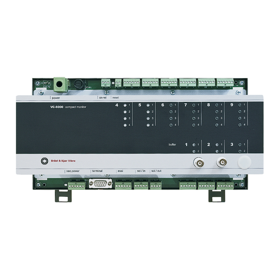
The name plate Part A VC 6000 Compact monitor The name plate Some important information about your VIBROCONTROL 6000 Compact monitor can be found on the name plate. Company name Product name Instrument configuration Power data Material number Serial number Date of manufacture •... -
Page 17: The Signal-Flow Chart
DC output characteristics, etc.) can be edited using the User-terminal. These setting options are identified in parameter configuration sheet. Each VIBROCONTROL 6000 Compact monitor has a valid signal-flow chart and a valid parameter configuration sheet. In this signal-flow chart and the parameter configuration sheet all existing available components in the system, with their links, are displayed in an overview. - Page 18 The signal-flow chart Part A VC 6000 Compact monitor Example of a signal-flow chart © VC 6000 Compact monitor Juni 2014 C100575.002 Introduction Vers.10 - 8 -...
-
Page 19: Parameter Configuration Sheet
Parameter configuration sheet Part A VC 6000 Compact monitor Parameter configuration sheet The parameters that are preset in the basic configuration are entered in the parameter setting sheet. If the preset parameters are changed with the use of the User Terminal, the changes can be entered on the parameter setting sheet in a further column. - Page 20 Parameter configuration sheet Part A VC 6000 Compact monitor Example of a parameter configuration sheet): © VC 6000 Compact monitor Juni 2014 C100575.002 Introduction Vers.10 - 10 -...
-
Page 21: The Configuration Sheet
♦ How the connection plugs are laid out ♦ Which LEDs are assigned to which channels. This information is required to be able to put a VIBROCONTROL 6000 Compact monitor into operation. Example of a configuration sheet: © VC 6000 Compact monitor Juni 2014 C100575.002 Introduction Vers.10... -
Page 22: Plug To Socket Position Arrangement (In The Example)
The configuration sheet Part A VC 6000 Compact monitor Explanation of the example: ♦ In this example not all the available sockets are occupied. Depending on the monitoring task, it is possible that not all or other module sockets will be necessary in a particular case. -
Page 23: System Reliability
System reliability Part A VC 6000 Compact monitor System reliability Standards conformity C-ticking confirms conformity with the EMV requirements of the Australian Government Agency (ACA) Safety EN 61010-1 “ CB Test Certificate IEC 61010-1 : 2001 EN 61326-1 “ Temperature DIN EN 60068-2-1 : 1995-03 Cold 20 °C Working... - Page 24 System reliability Part A VC 6000 Compact monitor © VC 6000 Compact monitor Juni 2014 C100575.002 Introduction Vers.10 - 14 -...
-
Page 25: Technical Data
CAUTION HIGH VOLTAGE! The housing cover of the may be VIBROCONTROL 6000 Compact monitor removed only by technical personnel!! Due to the principle conditions of heat development of the current outputs of the DC output modules, a maximum of 3 DC output modules can be permitted at this ambient temperature. -
Page 26: Ok-Monitoring Function
Please note that making contact with these voltages at the relays may cause injury or damage, even if the power to the VIBROCONTROL 6000 Compact monitor itself is switched off. © VC 6000 Compact monitor Juni 2014 C100575.002 Introduction Vers.10... -
Page 27: Channel Over-Ranging Identification Function
System reliability Part A VC 6000 Compact monitor The OK-relay in the User-terminal dialogue: ♦ In the dialogue there are one parameter for the OK-relay: ◊ Reset ♦ The parameter <Reset> in the dialogue will reset the latching OK-relay after a fault has occurred, on condition the fault no longer exists. ♦... - Page 28 System reliability Part A VC 6000 Compact monitor Switch conditions and their meaning ♦ The green LED shows the current status of a relay output. • Relay enable off: The relay does not operate, a limit violation is displayed only by the LEDs •...
- Page 29 System reliability Part A VC 6000 Compact monitor LEDs – Status and meanings: Case Meaning green yellow enabled disabled There are no violations. green green A limit violation exists that has not been reset. green green A limit violation exists that has been reset.
-
Page 30: Instrument Conduct After A Power Failure
Compact monitor 8.3.4 Instrument conduct after a power failure If there is a power failure the VIBROCONTROL 6000 Compact monitor will be shut down and thus the monitoring function as well. In this case a Logbook entry is always recorded. -
Page 31: Significance Of The Logbook
2 of section D „Dialogue with the User Terminal“ 8.3.7 Calibration We recommend that the VIBROCONTROL 6000 Compact monitor be calibrated every 5 years. This will ensure that the correct functionality of the system is checked, and that the certification according to the quality standard is maintained. -
Page 32: Mounting And Installation
Mounting and Installation Part A VC 6000 Compact monitor Mounting and Installation Safety advice The general safety advice of Brüel & Kjær Vibro GmbH is applicable. ♦ The safety advice must be read and understood before putting the instrument into operation! ♦... -
Page 33: Site Conditions
Part A VC 6000 Compact monitor Site conditions With the installation of the VIBROCONTROL 6000 Compact monitor the following requirements for site conditions must be observed: ♦ VIBROCONTROL 6000 Compact monitor is designed for mounting onto a mounting rail according to DIN EN 50022. - Page 34 The screen of the connecting cable should be made flat when being connected to the grounding rail. ♦ The housing of the VIBROCONTROL 6000 Compact monitor is connected through the power supply and mounting rail to PE. ♦ Further advice for correct grounding of the housing and cable screens can be found in the brochure „General grounding prescriptions“.
-
Page 35: Mounting The Instrument
Mounting the instrument 9.4.1 Mounting on a rail according to DIN EN 50022 ♦ The mounting of the VIBROCONTROL 6000 Compact monitor has to be done according to the regulation in a control cabinet or protective housing ! ♦ Position the VIBROCONTROL 6000 Compact monitor on the rail and push downward until the instrument clips onto the rail. -
Page 36: Wiring And Connection Of Sensors
Mounting and Installation Part A VC 6000 Compact monitor 9.5.1 Wiring and connection of sensors The following connection diagrams are principle illustrations; please always observe the corresponding documentation, the sensors that will be connected or the subsequent electronics! 9.5.1.1 Acceleration sensors with –24 V DC power at A-TIM (-24 V) 9.5.1.2 Acceleration sensors with constant-current power (CCS) at A-TIM (CCS) ©... - Page 37 Mounting and Installation Part A VC 6000 Compact monitor 9.5.1.3 Vibration velocity sensors at V-TIM (8 Hz/15 Hz) 9.5.1.4 Displacement sensors at D-TIM © VC 6000 Compact monitor Juni 2014 C100575.002 Introduction Vers.10 - 27 -...
- Page 38 Mounting and Installation Part A VC 6000 Compact monitor 9.5.1.5 0/4..20 mA signals at GP input module (GP-TIM) 9.5.1.6 0/2...10 V signals at GP input module (GP-TIM) Note: At one GP-TIM either two current inputs or two voltage inputs can be used.
-
Page 39: Wiring And Connection Of Peripheral Equipment
Mounting and Installation Part A VC 6000 Compact monitor 9.5.2 Wiring and connection of peripheral equipment 9.5.2.1 DC output at DC-OUT (2-ch.) Note: A current or a voltage output signal may be selected for each channel separately. They do not have to be the same type of output signals ! ©... - Page 40 Because external voltages are connected to the relay contacts, there may be dangerously high voltages at these contacts even after the power to the VIBROCONTROL 6000 Compact monitor has been switched off. The maximum voltages and switching capacity of the relays must be strictly observed (see section B: Relays technical data).
-
Page 41: System Connections
Mounting and Installation Part A VC 6000 Compact monitor 9.5.3 System connections 9.5.3.1 AC power supply Recommended cross-sectional area for the connecting cables: 1,5 mm² 9.5.3.2 DC power supply Recommended cross-sectional area for the connecting cables: 1,5 mm² Caution! Maximally 75 V smoothed DC voltage may be attached ©... - Page 42 Mounting and Installation Part A VC 6000 Compact monitor 9.5.3.3 Redundant power supply input 9.5.3.4 OK relay © VC 6000 Compact monitor Juni 2014 C100575.002 Introduction Vers.10 - 32 -...
- Page 43 The peripheral components connection variants shown here do not claim to be comprehensive or complete. Please also consult the technical documentation of the peripheral equipment you wish to connect to the VIBROCONTROL 6000 Compact monitor © VC 6000 Compact monitor Juni 2014 C100575.002 Introduction Vers.10...
-
Page 44: Commissioning And Function Testing
♦ Checking the instrument using the signal-flow chart and the configuration sheet: The signal-flow chart shows the structure of the VIBROCONTROL 6000 Compact monitor ; the configuration sheet shows the physical construction and the connection plug layout. Using this documentation please check your VIBROCONTROL 6000 Compact monitor . -
Page 45: Function Testing
9.6.2 Function testing ♦ How will I know that the VIBROCONTROL 6000 Compact monitor is functioning correctly? All LEDs will be green and the connected outputs will be signalling no errors. ♦... -
Page 46: Digital Communication
For the data transfer the SCI-interface of the VIBROCONTROL 6000 Compact monitor is used together with an RS-232 converter (AC-5004). If the VIBROCONTROL 6000 Compact monitor is connected to a network, a Gateway (AC-5002) is also required. Detailed information about the SCI-interface can be found in section B –... -
Page 47: Typical Measurement Tasks
Typical measurement tasks Part A VC 6000 Compact monitor Typical measurement tasks 11.1 General As a rule the parameters to be set up are dependent on the application. All the parameters of an application are marked in the signal-flow chart. The parameters that can be changed are correspondingly identified. -
Page 48: Rolling-Element Bearing Condition Unit – Bcu
Typical measurement tasks Part A VC 6000 Compact monitor 11.2.2 Rolling-element Bearing Condition Unit – BCU Input sensitivity For vibration acceleration sensors 100 mV/g Measurement range 0 ... 100 BCU Averaging time Measurement < 4,5 % of measured value plus 0,2 % of measurement range accuracy full-scale value Monitoring... -
Page 49: Relative Shaft Vibration Acc. To Din Iso 7919
Typical measurement tasks Part A VC 6000 Compact monitor 11.2.4 Relative shaft vibration acc. to DIN ISO 7919 oder Input sensitivity For displacement sensors 8 mV/µm Measurement type in the frequency range from 10 Hz to 1 kHz resp. Max (x,y) peak-peak in the frequency range from 10 Hz to 1 kHz Measurement range 0 ... -
Page 50: Process Value
Typical measurement tasks Part A VC 6000 Compact monitor 11.2.6 Process value Input sensitivity 4 ... 20 mA corr. to 0 ... 150 eu Measurement type Quasi-static process value (DC-value) Measurement range 0 ... 150 eu Averaging time Measurement < 1 % of measured value plus 0,1 % of measurement range accuracy full-scale value 11.2.7 Speed... -
Page 51: Vector
Typical measurement tasks Part A VC 6000 Compact monitor 11.2.9 Vector Input sensitivity For vibration acceleration sensors 100 mV/g For vibration velocity sensors (e.g. VS-068/VS-069) 100 mV/mm/s For displacement sensors 8 mV/µm Measurement type Vector of 1n, with magnitude and phase Signal detection Bandwidth 22 %... -
Page 52: Contents Index For The Following Documentation
Contents index for the following documentation Part A VC 6000 Compact monitor Contents index for the following documentation Section B: Technical data of the modules BASE Module 1-channel input module for acceleration sensors 1-channel input module for vibration velocity sensors 1-channel input module for displacement sensors 2-channel input module for current / voltage 2-channel conditioning module for BCU... - Page 53 Contents index for the following documentation Part A VC 6000 Compact monitor Section C: Description of signal-flow chart components Sensor block Sensor-(A/B) block Binary in block Highpass / Lowpass Filter Trigger block BCU Measurement DC Measurement Speed Measurement Peak Measurement Peak-Peak Mesurement RMS Measurement Measurement...
- Page 54 Contents index for the following documentation Part A VC 6000 Compact monitor Section D: Dialogue with the User-terminal User Terminal Function Advice about the documentation Logging in to the system Setting reference time Navigating the signal-flow charts Displaying parameters Display of measurements Setting the sensor sensitivity and input range Setting limit setpoints and time delays Logbook...
- Page 56 All rights reserved. No part of this publication may be reproduced, stored in a retrieval system or transmitted, in any form, or by any means, electronic, mechanical, photocopying, recording or otherwise without prior written permission from Brüel & Kjær Vibro GmbH. The right to make changes at any time without notice is reserved.
- Page 57 Contents Part B VC-6000 Compact monitor Contents – Modules Technical Data BASE Module Function Construction 1.2.1 AC-board construction 1.2.2 DC-board construction Connection plugs on the Base Module 1.3.1 Overview 1.3.2 Socket position and assigned connection plug The connections – their function and layout 1.4.1 Sensor Interface Module: Connections X1, X2 and X3 1.4.2...
- Page 58 VC-6000 Compact monitor Part B Contents 1-channel input module for vibration velocity sensors Function Signal path Technical data 3.3.1 Electrical properties 3.3.2 Equipment and signalling 1-channel input module for displacement sensors Function Signal path Technical data 4.3.1 Electrical properties 4.3.2 Equipment and signalling 2-channel input module for current / voltage Function...
- Page 59 Contents Part B VC-6000 Compact monitor 3-channel input module for binary status signals Function Technical data 7.2.1 Electrical properties 7.2.2 Equipment and signalling Wiring of binary inputs 7.3.1 External potential-free contacts (non-active signals) 7.3.2 Active signals from external current sources (PNP open- collector) 7.3.3 Active signals from external current sinks (NPN open-collector) 2-channel Relay output module...
- Page 60 VC-6000 Compact monitor Part B Contents - 4 - C100584.002 Module Vers. 08 © VC-6000 Compact monitor Nov. 2014...
- Page 61 Function Base Module central hardware component . It has the following functions and VIBROCONTROL 6000 Compact monitor components: ♦ Base board AC with internal AC power supply ♦ Base board DC with internal DC power supply ♦ Digital Signal Processor (DSP) ♦...
- Page 62 VC-6000 Compact monitor Part B BASE Module Construction 1.2.1 AC-board construction 1.2.2 DC-board construction The DC board is identical to the AC board as far as the power supply and power connections are concerned. - 6 - C100584.002 Module Vers. 08 ©...
- Page 63 1.3.1 Overview ∗ Please note the corresponding plug layout for DC power on the DC Base board! See the configuration sheet of the VIBROCONTROL 6000 Compact monitor © VC-6000 Compact monitor Nov, 2014 C100584.002 Module Vers. 08 - 7 -...
- Page 64 (Yes) The connection plan for a is exclusively VIBROCONTROL 6000 Compact monitor determined through the hardware equipment in the module socket positions. E.g. Socket position no. 1 contains a A-TIM-24 V → the terminal layout of A-TIM-24 V is valid for plug X1, etc.
- Page 65 BASE Module Part B VC-6000 Compact monitor The connections – their function and layout 1.4.1 Sensor Interface Module: Connections X1, X2 and X3 The socket positions X1_M, X2_M and X3_M belong to the connections X1 to X3. These socket positions can be equipped with Sensor Interface Modules or the 2-channel conditioner module for BCU.
- Page 66 VC-6000 Compact monitor Part B BASE Module V-TIM (8 Hz) & V-TIM (15 Hz): Connection layout for 1-channel input module for VS-sensor Connection V-TIM (8 Hz and 15 Hz) X1/X2/X3 Pin 1 does not use Pin 2 does not use Pin 3 signal in (common) Pin 4...
- Page 67 BASE Module Part B VC-6000 Compact monitor BINARY-IN: Connection layout for 3-channel input module for binary status signals BINARY-IN Pin-connection layout (X1 –X3)X4 to X9 Signal Explanation HI A Channel A input SIG (HIGH) LO A Channel A input GND (LOW) HI B Channel B input SIG (HIGH) LO B...
- Page 68 VC-6000 Compact monitor Part B BASE Module 1.4.3 System: Connections X20 to X27 The connections X20 to X27 are system connections, and their function and connection layout is dependent on the hardware equipment. 1.4.3.1 Internal power supply: X20 – Power supply The internal power supply of the Base Module is provided with power through the connection X20.
- Page 69 1.4.3.2 External power supply: X23 – Input for Redundant power supply To increase the safety of a VIBROCONTROL 6000 Compact monitor against power failure it is possible to connect a 2nd power supply (redundant). It should be noted that only a power supply suitable for the power requirements of the internal power of the VIBROCONTROL 6000 Compact monitor should be used.
- Page 70 VIBROCONTROL 6000 Compact monitor by a binary signal. All events are reset and all sensor OK faults and relays in the latching mode will be reset. The Remote reset is activated when pins 1 and 2 of the connection X22 are briefly short-circuited;...
- Page 71 (AC-5003), a serial communication to a PC (RS-232 interface) or a connection to a TCP/IP network through a Gateway (AC-5004). This communication is required, e.g. for a firmware download or to connect a VIBROCONTROL 6000 Compact monitor with an OPC-server (OPC DA- server – Type 7131). Connection...
-
Page 72: Ac Power Supply
VC-6000 Compact monitor Part B BASE Module Technical data 1.5.1 Electrical power supply AC power supply Input voltage range 90 ... 264 V AC Frequency range 50 / 60 Hz Maximum power consumption 40 VA LED power supply monitor Green = OK, OFF = Interruption Instrument fuses (F101, F102) T2A IEC 127 Size 5 x 20 mm... -
Page 73: System Function
BASE Module Part B VC-6000 Compact monitor 1.5.3 System System function Processor DSP Type 56309@ 98,304 MHz Memory 16 Mbit Flash Measurement and Monitoring function A/D converter 6-channel with 14 bit resolution Sampling frequency 64 kHz per channel Signal processing all channels continuous Internal cycle time 5 ms... - Page 74 Sensor block (Firmware), i.e. an A-TIM and Sensor block together form a physical interface between the VIBROCONTROL 6000 Compact monitor the outside world. The measured signal from the sensor is acquired and made available to the signal path for further processing and assessment.
- Page 75 1-channel input module for acceleration sensors Part B VC-6000 Compact monitor Signal path ♦ The input to an A-TIM is a coupled differential input amplifier. The output signal of the input amplifier is passed on to two separate signal paths. Each path is assigned to an A/D converter channel.
- Page 76 VC-6000 Compact monitor Part B 1-channel input module for acceleration sensors Technical data 2.3.1 Electrical properties Input: Input voltage range -21,5 V ... + 2,5 V Frequency range of input signal > 0 ... 50 kHz Input impedance 200 kΩ Sensor Sensitivity analogue adjustable Amplification...
- Page 77 1-channel input module for acceleration sensors Part B VC-6000 Compact monitor 2.3.2 Equipment and signalling ♦ Possible socket positions on the Base Module: X1_M X2_M X3_M ♦ Connection plugs on the Base Module (dependent on the selected socket position): X1 A-TIM (-24 V) Pin layout connections X1/X2/X3 Signal Explanation...
- Page 78 VC-6000 Compact monitor Part B 1-channel input module for acceleration sensors ♦ LED OVERLOAD (RD) The red LED provides information about the condition of the A/D converter. This will provide information whether an over-range exists or has existed through the input signal or whether everything is in order. ♦...
- Page 79 The input module is managed internally by a Sensor block (Firmware), i.e. V-TIM and Sensor block together form a physical interface between the VIBROCONTROL 6000 Compact monitor and the outside world. The measured signal from the connected sensor is acquired and provided to the signal path for further processing and evaluation.
- Page 80 VC-6000 Compact monitor Part B 1-channel input module for vibration velocity sensors ♦ DC-Signal path (DC coupled processing path) This signal path has continuous access to the entire raw signal, including the available DC voltage part of the signal. In this path also the DC-operating point (sensor passive voltage) resulting from the sensor power supply is acquired and monitored (sensor OK-monitoring).
- Page 81 1-channel input module for vibration velocity sensors Part B VC-6000 Compact monitor 3.3.2 Equipment and signalling ♦ Possible socket positions on the Base Module X1_M X2_M X3_M ♦ Corresponding connections on Base Module ♦ Connection layout with a V-TIM V-TIM Pin layout connections X1/X2/X3 Signal Explanation Sensor signal reference potential...
- Page 82 VC-6000 Compact monitor Part B 1-channel input module for vibration velocity sensors Status Explanation No over-range Flashing at 2 Hz An over-range exists; not yet confirmed through the dialogue Flashing at 0,5 Hz Only with OK latching parameter: No existing over-range; an earlier over-range not yet confirmed through the dialogue Continuous over-range exists;...
- Page 83 The input module is internally managed through a Sensor block (Firmware), i.e. the D-TIM and Sensor block together form a physical interface between the VIBROCONTROL 6000 Compact monitor and the outside world. The signal from the connected sensor is acquired and made available to the signal path for further processing and evaluation.
- Page 84 VC-6000 Compact monitor Part B 1-channel input module for displacement sensors Technical data 4.3.1 Electrical properties Input: Input voltage range -21,5 V ... + 2,5 V Frequency range of input signal > 0 ... 50 kHz Input impedance 200 kΩ Sensor Sensitivity analogue adjustable Amplification...
- Page 85 1-channel input module for displacement sensors Part B VC-6000 Compact monitor ♦ LED OVERLOAD (RD) The red LED provides information about the condition of the A/D converter. This will provide information whether an over-range exists or has existed through the input signal or whether everything is in order. ♦...
- Page 86 The input module is managed internally through a Sensor(A/B) block (Firmware), i.e. GP-TIM and Sensor(A/B) block together form a physical interface between the VIBROCONTROL 6000 Compact monitor and the outside world. The measured signal from the connected sensor is acquired and made available to the signal path for further processing and evaluation.
- Page 87 2-channel input module for current / voltage Part B VC-6000 Compact monitor 5.2.2 Equipment and signalling ♦ Possible socket positions on the Base Module X1_M X2_M X3_M ♦ Connection plugs on the Base Module ♦ Connection plug layout of a GP-TIM GP-TIM Pin layout connections X1/X2/X3 Signal Explanation...
- Page 88 VC-6000 Compact monitor Part B 2-channel conditioning module for BCU 2-channel conditioning module for Function ♦ The conditioning module for BCU, abbreviated to BCU-CON (BCU- Conditioning Module), is laid out for two measuring channels. Two sensor signals can be evaluated independent of one another. ♦...
- Page 89 2-channel conditioning module for BCU Part B VC-6000 Compact monitor 6.2.2 Equipment and signalling ♦ Possible socket positions on the Base Module X2_M When the BCU-CON is located at position X2_M, it can be operated as a 2-channel module. The signals from socket positions X1_M and X3_M can be acquired and processed.
- Page 90 (firmware), i.e. a BINARY-IN input channel and a binary block together form a physical interface to the outside world for the VIBROCONTROL 6000 Compact monitor. The connected input signal is acquired and made available to the successive signal path for further processing and assessment, e.g.
- Page 91 3-channel input module for binary status signals Part B VC-6000 Compact monitor 7.2.2 Equipment and signalling ♦ Possible socket positions on the Base module X1_M to X9_M ♦ Connection plugs on the Base module X1 to X9 ♦ Connection plug layout with BINARY-IN equipment BINARY-IN Connection pin layout X4 to X9 Signal Explanation...
- Page 92 VC-6000 Compact monitor Part B 3-channel input module for binary status signals Wiring of binary inputs 7.3.1 External potential-free contacts (non-active signals) VIBROCONTROL 6000 VIBROCONTROL 6000 Compact monitor Compact monitor Machine control Machine control Binary input Binary input Binäreingang (050805) Binäreingang (050805)
- Page 93 3-channel input module for binary status signals Part B VC-6000 Compact monitor 7.3.3 Active signals from external current sinks (NPN open-collector) VIBROCONTROL 6000 VIBROCONTROL 6000 Compact monitor Compact monitor Machine control Machine control + 24 V + 24 V + 24 V...
-
Page 94: Electrical Data
VC-6000 Compact monitor Part B 2-channel Relay output module 2-channel Relay output module Function ♦ The relay output module is laid out for two output channels. Each output channel uses a change-over relay for switching of potential-free contacts. ♦ Each relay output module has 4 LEDs, of which 2 are respectively assigned to one relay. - Page 95 2-channel Relay output module Part B VC-6000 Compact monitor 8.2.2 Connection plug layout Relay output module pin layout connections X1/X2/X3 Signal Explanation ARM RelA Arm, relay A NO RelA Normally-open contact, relay A NC RelA Normally-closed contact, relay A ARM RelB Arm, relay B NO RelB Normally-open contact, relay B...
- Page 96 VC-6000 Compact monitor Part B 2-channel Relay output module Wiring of relay outputs 8.3.1 Relay switch mode When connnecting the relay contact it should be noted that the relay outputs can be operated selectively as normally de-energised or normally energised relays (see figure for details) Pins no.
- Page 97 Controlling an external power relay The relay output module is laid out for switching low power. If higher power switching is required this can be realised through supplementary externally mounted power relays. VIBROCONTROL 6000 VIBROCONTROL 6000 Compact monitor Compact monitor...
- Page 98 VIBROCONTROL 6000 Compact monitor and the outside world. The output can be selected as a potential-free DC-current signal (e.g. 4 ... 20 mA) or a potential-free DC voltage signal (e.g. 0 ... 10 V). Both signal types are presented at each DC-OUT Module. Selection is done respectively through a corres-ponding connection layout.
- Page 100 All rights reserved. No part of this publication may be reproduced, stored in a retrieval system or transmitted, in any form, or by any means, electronic, mechanical, photocopying, recording or otherwise without prior written permission from Brüel & Kjær Vibro GmbH. The right to make changes at any time without notice is reserved.
- Page 101 Contents Part C VC-6000 Compact monitor Contents - Components Sensor block ................7 Function ......................7 Parameters and setting ranges ............... 7 1.2.1 Parameter list ..........................7 1.2.2 Summary of the parameters ....................10 Sensor-(A/B) block ..............11 Function ......................11 Parameters and setting ranges for GP-TIM ..........
- Page 102 Part C Contents VC-6000 Compact monitor Summary of parameters for signal filtering ........... 22 4.3.1 Analogue signal integration .....................22 4.3.2 Frequency response linearisation ...................22 Trigger block ................23 Function ......................23 Parameters and setting ranges ..............23 5.2.1 Parameter list ..........................23 5.2.2 Summary of the parameters ....................24 BCU measurement ..............
- Page 103 Contents Part C VC-6000 Compact monitor Peak-peak measurement ............38 11.1 Function ......................38 11.2 Parameters and setting ranges ..............39 11.2.1 Parameter list ..........................39 11.2.2 Summary of the parameters ....................39 Cyclic peak-peak measurement ..........40 12.1 Function ......................40 12.2 Parameters and setup ranges ...............
- Page 104 Part C Contents VC-6000 Compact monitor MIN-HOLD measurement ............48 16.1 Function ......................48 16.2 Parameters and setup ranges ............... 49 16.2.1 Display parameters .........................49 16.2.2 Configuration parameters ......................49 16.2.3 Parameter summary ........................49 Vector measurement ..............50 17.1 Function ......................50 17.2 Parameters and setting ranges ..............
- Page 105 Contents Part C VC-6000 Compact monitor Dual-Monitor (2 absolute limit values) function ......65 21.1 Parameters and setting ranges ..............65 21.1.1 Parameter list ..........................65 21.1.2 Summary of the parameters ....................69 Logic Block for relay control ............70 22.1 Function ......................70 22.2 Typical variants of the Logic block ..............
- Page 106 Part C Contents VC-6000 Compact monitor - 6 - C100583.002 Components Vers. 07 © VC-6000 Compact monitor Sept. 2011...
-
Page 107: Sensor Block
<Socket no.> This parameter provides information about the physical socket number of the 1-channel input module. The settings are determined through the application firmware of the VIBROCONTROL 6000 Compact monitor and cannot be changed at the instrument. Note: The measurement and monitoring function of an input channel is guaranteed only when the physical module configuration is not changed! Socket no. - Page 108 The unit of sensitivity (e.g. mV/g or V/m/s) is determined by the application firmware of the VIBROCONTROL 6000 Compact monitor and cannot be changed at the instrument. The numeric value of the sensitivity can be changed within its setting range.
- Page 109 Sensor block Part C VC-6000 Compact monitor Maximum set-points for AS sensors: The input signal is automatically integrated by the application if an acceleration sensor is used to monitor the vibration speed. The maximum <input range> is limited to 300 mm/s in this configuration. ...
-
Page 110: Summary Of The Parameters
♦ <Hardware Id> This parameter informs you about the type of the 1-channel input module. The setting is determined by the application firmware of the VIBROCONTROL 6000 Compact monitor and cannot be changed at the instrument. Hardware-Id Module A-TIM (CCS) -
Page 111: Sensor-(A/B) Block
♦ <Socket no.> This parameter informs you about the physical socket number of the input module. The settings are determined by the application firmware of the VIBROCONTROL 6000 Compact monitor and cannot be changed at the instrument. Note: The measurement and monitoring function of an input channel is guaranteed only when the physical module configuration is not changed! Socket no. - Page 112 Part C Sensor-(A/B) block VC-6000 Compact monitor ♦ < OK-high A> and < OK-high B> (OK-window OK-LED) This parameter defines the high limit value of the OK-window for channel A and channel B. The OK-high limit is always an absolute voltage value in the unit [V] or an absolute current value in the unit [mA].
-
Page 113: Summary Of The Parameters For Gp-Tim
♦ <Socket no.> This parameter informs you about the physical socket number of the input module. The settings are determined by the application firmware of the VIBROCONTROL 6000 Compact monitor and cannot be changed at the instrument. Note: The measurement and monitoring function of an input channel is guaranteed only when the physical module configuration is not changed! Socket no. -
Page 114: Summary Of Parameters For Bcu-Con
Part C Sensor-(A/B) block VC-6000 Compact monitor ♦ <OK latching> This parameter defines whether the OK LED will operate in a latching or non-latching mode. The setting can be changed at the instrument. Settings: OK latching ♦ <Hardware Id> This parameter informs you about the type of input module. The settings are determined by the application firmware and cannot be changed at the instrument. -
Page 115: Binary-Input Block
<Socket no.> This parameter provides information about the physical socket number of the BINARY-IN module on the Base module. The settings are defined by the application firmware of the VIBROCONTROL 6000 Compact monitor and cannot be changed at the instrument. Note: ... - Page 116 Part C Binary-input block VC-6000 Compact monitor ♦ <Active Signal> This parameter switches an auxiliary voltage within the BINARY-IN module either on or off. Active signals from external current sources or open collector outputs require no auxiliary voltage. Non-active signals from external potential-free contacts require an auxiliary voltage.
-
Page 117: Summary Of The Parameters
♦ <Hardware ID.> This parameter provides information about the input module type. The settings are defined by the application firmware of the VIBROCONTROL 6000 Compact monitor and cannot be changed at the instrument. Hardware ID. 3.2.2 Summary of the parameters... -
Page 118: Highpass / Lowpass Filter
(e.g. 3 order Butterworth filter). ♦ integration acceleration signals VIBROCONTROL 6000 Compact monitor can also be effected by analogue techniques because with signal integration, analogue filters have the best technical measurement properties. Parameter list with setting ranges Note: In the user menu of the User Terminal all filters are exclusively designated only as highpass filter or lowpass filter. -
Page 119: Bandpass Filter Acc. To Din Iso
Highpass / Lowpass filter Part C VC-6000 Compact monitor 4.2.1 Bandpass filter acc. to DIN ISO The bandpass filter according to the recommendations of DIN ISO 10816 consists of limited adjustment highpass filter and a fixed setting lowpass filter. 4.2.2 Lowpass filter acc. -
Page 120: Bandpass Filter For Rolling-Element Bearing Condition
Part C Highpass / Lowpass filter VC-6000 Compact monitor 4.2.4 Bandpass filter for rolling-element bearing condition The bandpass filter for the assessment of rolling-element bearing condition consists of a highpass filter and a lowpass filter each with a respectively fixed corner frequency. 4.2.5 Lowpass filter for rolling-element bearing condition ♦... -
Page 121: Variable Highpass Filter
Highpass / Lowpass filter Part C VC-6000 Compact monitor 4.2.9 Variable highpass filter ♦ <Corner frequency > of the filter: The corner frequency of the variable highpass filter is as a rule preset to 10 Hz. The settings in the instrument can be changed according to the values shown in table 2. -
Page 122: Summary Of Parameters For Signal Filtering
Part C Highpass / Lowpass filter VC-6000 Compact monitor Summary of parameters for signal filtering Note: In the user menu of the User _Terminal the supplementary parameters are not displayed. The actual construction steps of each signal path can respectively be taken from the individual instrument docu- mentation (signal-flow chart). -
Page 123: Trigger Block
Trigger block Part C VC-6000 Compact monitor Trigger block Function ♦ The Trigger block is an optional signal path component. It contains all necessary parameters to process trigger signals (impulses). The input signal (impulse) is compared to a trigger level to create an event sequence (series of reference time points). -
Page 124: Summary Of The Parameters
Part C Trigger block VC-6000 Compact monitor ♦ <Trigger level> This parameter is relevant only for the fixed-value trigger option and determines the level of the fixed-value trigger. Minimum: -25.0 V Maximum: + 25.0 V Step size: 0.01 Works pre-setting -15.0 V ♦... -
Page 125: Bcu Measurement
BCU measurement Part C VC-6000 Compact monitor BCU measurement Function ♦ The BCU value is a proprietary measurement variable for the assessment of rolling-element bearing condition according to the BEARCON technique. ♦ BCU measurement is an optional signal path component. As a configuration interface, it also contains a group of parameters necessary for the setting. -
Page 126: Summary Of The Parameters
Part C BCU measurement VC-6000 Compact monitor ♦ <Multiplier> and <Divider> These two parameters can be used for normalising the BCU measurement. Both parameters are integral values that can be changed within a setting range. The following is valid: BCU = BCU * multiplier / divider normalised... -
Page 127: Dc Measurement
DC measurement Part C VC-6000 Compact monitor DC measurement Function ♦ The DC value describes the quasi-static DC part of a signal (DC signal, DC part of an AC/DC signal). ♦ A DC measurement is used to determine quasi-static measurements such as GAP voltage, axial shaft position, process values, etc. -
Page 128: Summary Of The Parameters
Part C DC measurement VC-6000 Compact monitor ♦ <Zero offset> The zero offset of the units of the DC measured value. The set value corresponds to the measurement at an input of 0V or 0 mA. Example: Measured signal 4-20 mA at measurement range 0-16 eu → zero offset is at -4 eu. -
Page 129: Speed Measurement
Speed measurement Part C VC-6000 Compact monitor Speed measurement Function ♦ The Speed measurement is a signal path component to accurately acquire a scalar measured value, e.g. the rotational speed of a shaft or the time span between two trigger signals. ♦... -
Page 130: Parameters And Setting Ranges
Part C Speed measurement VC-6000 Compact monitor Parameters and setting ranges 8.2.1 Parameter list ♦ <Meas. time> This parameter gives the measuring time. After the measuring time has expired the next trigger event ends the current measurement cycle. The actual measurement time corresponds to the sum of the predefined measuring time and the residual time span to the next trigger event. -
Page 131: Summary Of The Parameters
Speed measurement Part C VC-6000 Compact monitor ♦ <Divider> This parameter can have two functions: • Whether together with the parameter „Multiplier“ the transfer ratio should be taken into consideration, or • whether the speed measurement processes a number of trigger events per revolution and the divider must compensate for this., e.g. -
Page 132: Vibration Measurement
Part C Vibration measurement VC-6000 Compact monitor Vibration measurement Function ♦ Vibration measurement is a Firmware component for the acquisition of vibration from one AC signal. ♦ The vibration signal detection type is selectable between RMS, Peak and Peak-peak. ♦ The RMS value (Root Mean Square) is identical to the effective value of a vibration signal (AC-Signals). -
Page 133: Parameters And Setting Ranges
Vibration measurement Part C VC-6000 Compact monitor Parameters and setting ranges 9.2.1 Display parameters ♦ <Vibration value> The parameter „Vibration value“ displays the current measured value. RMS value Current measured value with units and signal detection ♦ <Unit> The unit of the measurement value is displayed together with the measured value. - Page 134 Part C Vibration measurement VC-6000 Compact monitor ♦ <Peak and Peak-peak evaluation:> The highest (and lowest) value is used for the calculation of the peak or peak-peak values. After the measurement time has expired the value is actualised and the next measurement cycle begins. Minimum: 0.1 s Maximum: 100.0s Increment...
-
Page 135: Parameter Summary
Vibration measurement Part C VC-6000 Compact monitor 9.2.3 Parameter summary Parameter name Value range adjustable Vibration value Display only Unit m/s², g, mm/s, in/s, µm, mils, eu, mV Detector RMS, peak, peak-peak Measuring time 0.1 s...100 s © VC-6000 Compact monitor Sept.2011 C100583.002 Components Vers. -
Page 136: Peak Measurement
Part C Peak measurement VC-6000 Compact monitor Peak measurement 10.1 Function ♦ The peak value describes the largest dynamic excursion of a vibration signal (AC signal) from its position of rest or centre point. Thus it is a measurement variable which, in contrast to an RMS value, is not directly linked in any way to the signal energy. -
Page 137: Summary Of The Parameters
Vibration measurement Part C VC-6000 Compact monitor ♦ <Decay time> The decay time parameter corresponds to the discharge time constant of the peak value measurement. The decay time can be changed within its setting range. Setting range of the time constant for the decay time: Minimum: 0,1 s Maximum: 9,9 s Step size: 0,1 s... -
Page 138: Peak-Peak Measurement
Part C Peak-peak measurement VC-6000 Compact monitor Peak-peak measurement 11.1 Function ♦ The peak-peak value describes the largest dynamic excursion of a vibration signal (AC or AC/DC signal) from the positive to the negative peak. Thus it is a dynamic measurement variable which, in contrast to an RMS value, is not directly linked in any way to the signal energy. -
Page 139: Parameters And Setting Ranges
Vibration measurement Part C VC-6000 Compact monitor 11.2 Parameters and setting ranges 11.2.1 Parameter list ♦ <Rise time> The parameter ‚Rise time’ corresponds to the charge time-constant of the peak-peak measurement. The rise time can be set up within a specific setting range. -
Page 140: Cyclic Peak-Peak Measurement
Part C Cyclic peak-peak measurement VC-6000 Compact monitor Cyclic peak-peak measurement 12.1 Function ♦ The cyclic peak-peak value describes the largest dynamic excursion of a vibration signal (AC signal or AC/DC signal) from the positive to the negative peak in relation to an external trigger signal. It is therefore a super-energetic measurement variable which, in contrast to the RMS value, is not directly associated with the signal energy. -
Page 141: Configuration Parameters
Cyclic peak-peak measurement Part C VC-6000 Compact monitor 12.2.2 Configuration parameters ♦ <Rise time> The parameter rise time corresponds to the charge time-constant of the peak-peak measurement. The rise time can be adjusted within the setup range. Setup range for the time-constant of the rise time: Minimum: 0 ms Maximum: 99 ms Increment size... -
Page 142: Parameter Summary
Part C Cyclic peak-peak measurement VC-6000 Compact monitor 12.2.3 Parameter summary Parameter name Setup range adjustable Cyclic P-P value Display only Unit m/s², g, in/s², mm/s², in/s, µm, mils, eu, 1 Rise time 1 ms...99 ms No. of averages 1 … 999 Time out 0.1 s..100.0 s - 42 -... -
Page 143: Rms Measurement
RMS measurement Part C VC-6000 Compact monitor RMS measurement 13.1 Function ♦ The RMS value (Root Mean Square) is identical to the effective value of a vibration signal (AC signal). Mathematically speaking it is the square root of the quadratic average value of the signal and, as a result, is a measure of the energy content of a vibration. -
Page 144: Parameters And Their Setting Ranges
Part C Cyclic peak-peak measurement VC-6000 Compact monitor 13.2 Parameters and their setting ranges ♦ <Averaging time> The averaging time parameter defines the time period over which the RMS measurement value will be averaged. The averaging time can be changed within its setting range. The setting range is from 25 ms to 204,800 ms. -
Page 145: 14 S Max Measurement
smax measurement Part C VC-6000 Compact monitor measurement 14.1 Function ♦ An s measurement is a dynamic displacement measurement for monitoring relative shaft vibration according to DIN ISO 7919. The measured value formed coresponds to the peak value of the dynamic excursion of a shaft from its centre position. -
Page 146: Summary Of The Parameters
Part C Cyclic peak-peak measurement VC-6000 Compact monitor ♦ <Decay time> The decay time parameter corresponds to the discharge time-constant of the s measurement. The decay time can be changed within its setting range. Setting range for the time-constant of the decay time: Minimum: 0.1 s Maximum: 9.9 s Step size: 0.1 s... -
Page 147: Max-Hold
MAX-HOLD Part C VC-6000 Compact monitor MAX-HOLD 15.1 Function ♦ The MAX-HOLD measurement continuously acquires the maximum value of the scalar value. ♦ The maximum value is continuously overwritten by any new higher value. ♦ The MAX-HOLD measurement is an optional signal path component. The MAX-hold measurement is arranged in the signal-flow chart directly after a measurement value component. -
Page 148: Configuration Parameters
Part C Cyclic peak-peak measurement VC-6000 Compact monitor 15.2.2 Configuration parameters ♦ <Reset / Reset> The Reset parameter deletes the currently saved MAX-HOLD value so that a new maximum value can be saved. The parameter can be activated via an OPC-server or a BINARY-IN. Reset 15.2.3 Parameter summary Parameter name... -
Page 149: Parameters And Setup Ranges
MIN-HOLD measurement Part C VC-6000 Compact monitor 16.2 Parameters and setup ranges 16.2.1 Display parameters ♦ <Min value> Corresponds to the actual stored value. Min value Current value ♦ <Unit> The unit parameter is determined by the application firmware creation and can only be changed by a new firmware download. -
Page 150: Vector Measurement
Part C Cyclic peak-peak measurement VC-6000 Compact monitor Vector measurement 17.1 Function ♦ The Vector measurement is a signal component for accurate measurement and calculation of the magnitude and phase of a vector (integer harmonic). This is X = X * n where = Vector resp. - Page 151 Vector measurement Part C VC-6000 Compact monitor ♦ <Unit> The parameter unit is in the preparation of the application firmware and is regulated by a firmware download changeable. Unit m/s², g, in/s², mm/s², in/s, µm, mils, eu, 1 ♦ <Phase> The parameter phase displays the value of the phase of the vector.
- Page 152 Part C Cyclic peak-peak measurement VC-6000 Compact monitor ♦ <Max. meas. time> The parameter „Max. Measurement time“ defines an upper time limit for the actual measurement. Normally the actual measurement time is clearly determined from the selected bandwidth. Minimum: 0.1 s Maximum: 99.99 s Step size: 0.01 Works pre-setting...
-
Page 153: Summary Of The Parameters
Vector measurement Part C VC-6000 Compact monitor ♦ <Time out> This parameter defines the maximum time interval between sequential trigger events. If the time interval is greater than the defined time, the measurement task is stopped (zero-speed criterion). The measurement task is automatically started when a new trigger event no longer fulfils the zero-speed criterion. -
Page 154: Centre Frequency, Bandwidth And Required Measuring Time
Part C Cyclic peak-peak measurement VC-6000 Compact monitor 17.2.3 Centre frequency, bandwidth and required measuring time Trigger- 44 % 22 % 11 % Relative Bandwidth* frequency No. of trigger periods Req’d measuring time 10 s 20 s 40 s 80 s 0,2 Hz Absolute bandwidth 0,088 Hz 0,044 Hz... -
Page 155: Cycle-Dc Measurement
Cycle-DC measurement Part C VC-6000 Compact monitor Cycle-DC measurement 18.1 Function ♦ The Cycle-DC value describes the quasi-static DC part of a signal (DC signal, DC-component of an AC/DC signal), whereby the measurement acquisition is sychronized with a trigger cycle. ♦... - Page 156 Part C Cyclic peak-peak measurement VC-6000 Compact monitor ♦ The Cycle-DC measurement has three operating modes: ◊ One measurement position per trigger cycle Phasenreferenz-Sensor Phasenreferenz-Sensor Wegsensor Wegsensor Kolbenhub Kolbenhub Kreuzkopf Kreuzkopf Messpunkt Messpunkt Länge L1 Länge L1 Kolbenring Kolbenring Kurbel w elle Kurbel w elle Länge L2 Länge L2...
-
Page 157: Parameters And Setting Ranges
Cycle-DC measurement Part C VC-6000 Compact monitor ◊ Continuous averaging of complete trigger cycles While continuous averaging the length L1 is equal the length L2 (L1=L2), from this arises a geomtry factor of 1. Length L1: Distance between crosshead and the con-rod centre position Length L2: Distance between crosshead and piston ring... - Page 158 Part C Cyclic peak-peak measurement VC-6000 Compact monitor ♦ <Zero offset> This parameter determines the zero point. The required value at the zero point is added to the measured value and the result is the final read value, i.e. the zero point that is set corresponds to the measurement result when the input signal is 0 V.
-
Page 159: Summary Of The Parameters
Cycle-DC measurement Part C VC-6000 Compact monitor ♦ <Multiplier> The Multiplier is length L2 (distance between crosshead and piston ring) Minimum: 1 Maximum: 99999 Step size: 1 Works pre-setting ♦ <Divider> The Divider is length L1 (distance between crosshead andthe con-rod centre position). -
Page 160: Calculated Scalar Values
(computations); e.g. Max(X,Y)p-p, Crest Factor, sm@rt- values etc. ♦ If a VIBROCONTROL 6000 Compact monitor device configuration has the functionality to calculate derived scalar values, each calculated value is represented in its own block within the signal-flow chart. The ’shaping’... -
Page 161: Max (X,Y) Peak-Peak
Calculated scalar values Part C VC-6000 Compact monitor 19.2 Max (X,Y) peak-peak ♦ Measurement method B for monitoring shaft vibration according to DIN ISO 7919: An X/Y displacement sensor pair with relative orthogonal measurement directions produces two measured peak-peak values, of which only the greater of both current values is used for further assessment. -
Page 162: Monitor (Absolute) Block
Part C Monitor (Absolute) block VC-6000 Compact monitor Monitor (Absolute) block 20.1 Function ♦ The Monitor (Absolute) block is responsible for limit setpoint monitoring with absolute limit values. In the User Menu the block name is abbreviated to Monitor(Absolute). For the alert alarm, danger alarm and other limit values there is a respective Monitor (Absolute) block. - Page 163 Monitor (Absolute) block Part C VC-6000 Compact monitor ♦ <Limit setpoint> This parameter defines the absolute limit setpoint of the Monitor block, with which each measurement will be compared. The unit of the limit is of course identical with that of the preceding Measurement block. The setting can be changed at the instrument.
-
Page 164: Summary Of The Parameters
In the simplest case the switching on and off is done through a binary status signal. If the VIBROCONTROL 6000 Compact monitor is not equipped with this <Trip Multiplier> function, the <Trip Multiplier> will not appear. -
Page 165: Dual-Monitor (2 Absolute Limit Values) Function
Dual-Monitor (2 absolute limit values) functionPart C VC-6000 Compact monitor Dual-Monitor (2 absolute limit values) function ♦ The Dual-Monitor(Absolute) block is responsible for limit monitoring with two absolute limit values. In the User Menu the block name is abbreviated to D.-MONI.(Abs.). ♦... - Page 166 Part CDual-Monitor (2 absolute limit values) function VC-6000 Compact monitor ♦ <Alert setpoint> This parameter defines the absolute value for the Alert alarm with which the measured value is compared in the Dual-Monitor block. The unit for the limit value is identical to that of the preceding Measurement block. The setting can be changed at the instrument.
- Page 167 Dual-Monitor (2 absolute limit values) functionPart C VC-6000 Compact monitor ♦ <Danger delay> The parameter Danger delay defines the time period that the Danger limit violation must continuously exist before the alarm event will be passed further to the following block (e.g. Relay output). This setting can be changed at the instrument.
- Page 168 In the simplest case the switching of the function on and off is achieved by means of a binary status signal. If the VIBROCONTROL 6000 Compact monitor is not equipped with the <Trip Multiply> function the parameter <Trip Multiply> will not be displayed.
-
Page 169: Summary Of The Parameters
Dual-Monitor (2 absolute limit values) functionPart C VC-6000 Compact monitor 21.1.2 Summary of the parameters Parameter name Value range changeable Limit type Upper or Lower limit Alert setpoint -99999.99...+ 99999.99 Danger setpoint -99999.99...+ 99999.99 Hysteresis -99999.99...+ 99999.99 Alert delay 0.00 s...99.99 s Danger delay 0.00 s...99.99 s Acknowledge... -
Page 170: Logic Block For Relay Control
According to the configuration the relay is controlled by logic selection criteria (e.g. 2-of-3 redundancy). When a VIBROCONTROL 6000 Compact monitor has this function this will be noted in the signal-flow chart of the instrument. ♦... -
Page 171: And-Link
Logic Block for relay control Part C VC-6000 Compact monitor 22.2.2 AND-link An AND-link is used e.g. for 2-of-2 logic. AND logic (Example with 2 inputs) Input 1 Input 2 Output Relay position Normal status Normal status Normal status Reporting status 0 = OFF ;... -
Page 172: 2-Of-4 Logic
Part C Logic Block for relay control VC-6000 Compact monitor 22.2.4 2-of-4 logic The 2-of-4 logic is predominantly employed when a high level of reliability for the signal (and as the case may be for the machine shut-down) is desired. 2–of–4 logic Input Output... -
Page 173: 3-Of-4 Logic
Logic Block for relay control Part C VC-6000 Compact monitor 22.2.5 3-of-4 logic The 3-of-4 logic is predominantly employed when a high level of reliability for the signal (and as the case may be for machine shut-down) is desired. 3–of–4 logic Input Output Relay position... -
Page 174: Dc Output
This parameter informs you about the physical socket number of the corresponding DC output, or the associated output module. The settings are determined by the application firmware of the VIBROCONTROL 6000 Compact monitor and cannot be changed at the instrument. ... - Page 175 DC output Part C VC-6000 Compact monitor ♦ <Signal output> This parameter defines whether the DC output will be operated with an offset (e.g. 4-20 mA, 2 -10 V) or without one (e.g. 0-20 mA, 0-10 V). If either of the settings <4-20 mA / 2 -10 V> is selected, invalid measurements / measurement outputs are signalled to the peripheral electronic equipment as 2 mA - or 1 V - signals.
- Page 176 Part C DC output VC-6000 Compact monitor The Y-values of anchor points corresponds to the desired output signal with reference to the maximum output signal. The available range is from 0 (corresponding to 0 %) to 1 (correspondig to 100 %). The associated voltage or current output is dependent on the parameter <Signal output>: ◊...
- Page 177 <Hardware Id.> This parameter informs you about the type of the output module. The settings determined applicaton firmware VIBROCONTROL 6000 Compact monitor and cannot be changed at the instrument. Hardware Id. © VC-6000 Compact monitor Sept.2011 C100583.002 Components Vers. 07...
-
Page 178: Summary Of The Parameters
Part C DC output VC-6000 Compact monitor 23.2.2 Summary of the parameters Parameter name Value range changeable Socket no. 1 to 9 Channel no. A or B Signal output 4-20 mA/ 2-10 V or 0-20 mA / 0-10 V X-values -99999.99...+ 9999.99 Y-values 0 to 1... -
Page 179: Relay Block
♦ <Socket no.> This parameters provides information about the physical socket number of the relay output module. The settings are determined by the application firmware of the VIBROCONTROL 6000 Compact monitor and cannot be changed at the instrument. Note:... - Page 180 This parameter provides information about the physical channel layout of the relay output on the associated Relay-output module. setting defined application firmware VIBROCONTROL 6000 Compact monitor and cannot be changed at the instrument. Possible channel numbers A or B ♦ <Reset>...
-
Page 181: Summary Of The Parameters
Relay block Part C VC-6000 Compact monitor ♦ <Hardware Id.> This parameter provides information about the type of output module. This parameter is defined by the application firmware and cannopt be changed at the instrument. Hardware Id. 24.2.1 Summary of the parameters Parameter name Value range changeable... -
Page 182: Com Block
25.1 Function ♦ The VIBROCONTROL 6000 Compact monitor is able to export, in digital form, the continuously acquired measurement variable over a network. For this purpose the Communications block has an OPC-interface (OPC = OLE for process control) available, which can be integrated in a TCP/IP Ethernet network. -
Page 183: Parameters And Their Setting Ranges
VIBROCONTROL 6000 Compact monitor in the network. Because many VIBROCONTROL 6000 Compact monitor in a network can communicate with a common OPC DA-server – Type 7131 , each individual VIBROCONTROL 6000 Compact monitor must be assigned a unique instru-ment address (device address). - Page 186 All rights reserved. No part of this publication may be reproduced, stored in a retrieval system or transmitted, in any form, or by any means, electronic, mechanical, photocopying, recording or otherwise without prior written permission from Brüel & Kjær Vibro GmbH. The right to make changes at any time without notice is reserved.
- Page 188 Contents Part D VC-6000 Compact monitor Contents - Dialogue with the User Terminal User Terminal Function How is the User Terminal connected? The push-buttons The display Advice about the documentation The menu levels 3.1.1 The Start level 3.1.2 Block level 3.1.3 Parameter level 3.1.4...
- Page 189 VC-6000 Compact monitor Part D Contents Displaying parameters Editing parameters 7.1.1 Editing parameter settings with discrete selection: 7.1.2 Editing continuously variable parameter settings: Displaying measurements Setting of sensor sensitivity and input range General Setting up the sensor sensitivity Setting the sensor input range Setting of limit setpoints and time delays 10.1 General...
- Page 190 Contents Part D VC-6000 Compact monitor Logbook 11.1 General 11.2 How are Logbook entries displayed? 11.3 Which parameters are in the Logbook block? 11.4 How is a Logbook entry structured? 11.5 Signalling of the OK-LED 11.6 Possible logbook entries 11.6.1 Logbook entries for access events 11.6.2 Logbook entries for monitoring events...
- Page 191 VC-6000 Compact monitor Part D Contents - 4 - C100585.002 Communication Vers. 03 © VC-6000 Compact monitor Dec 09...
- Page 192 ♦ The User-terminal is an operating accessory that is connected directly to by a connecting cable. This VIBROCONTROL 6000 Compact monitor permits a number of essential setting up tasks to be done on site and direct display of measured values.
-
Page 193: The Display
Part D Function How is the User Terminal connected? The User-terminal is connected directly through a 2,5 m long connection cable to socket X24 of the VIBROCONTROL 6000 Compact monitor . Note: The connecting cable may not be lengthened! - Page 194 Advice about the documentation Part D VC-6000 Compact monitor Advice about the documentation The operation of the User-terminal is illustrated by showing the button that is to be pushed (action), and the resulting display (reaction) is explained. Example: CV_112 Start DISPLAY 12345678 Enter button USER MENU 01...
- Page 195 VC-6000 Compact monitor Part D Advice about the documentation 3.1.2 Block level Start level Start level Block level Block level Parameter Parameter level level Display & Display & editing level editing level ♦ The Block level is directly below the Start level. At this level are the USER MENU, the CLOCK REFERENCE menu, the LOGBOOK, the System menu, all signal-flow components and the possible OK relay option selection points.
- Page 196 SAVE CHANGES is offered only when any settings have been changed. Password-protected menu access ♦ The menu system of the VIBROCONTROL 6000 Compact monitor is equipped with a password protection. There are two security steps: USER and SUPER USER. ♦...
-
Page 197: User Menus
ESCAPE(RETURN), in which the blocks of the signal-flow charts are also arranged. Note: You will receive the correct password for your VIBROCONTROL 6000 Compact monitor application firmware together with the signal-flow chart of your instrument. This is attached in section Individual instrument documentation of the handbook folder. -
Page 198: Selecting The Language
User Menus Part D VC-6000 Compact monitor What happens if the incorrect password is entered? If the incorrect password is entered, the dialogue will return to the start. USER MENU Log in Now the password can be entered once more. Without a successful login the user can only operate as a USER, without the authority to access and change the instrument settings. -
Page 199: Reset All
USER MENU ENTER BUTTON Monitoring Monitoring ENTER BUTTON CV_112 Start display on the DISPLAY 12345678 When Monitoring is switched On the Compact monitor VIBROCONTROL 6000 newly started. - 12 - C100585.002 Communication Vers. 03 © VC-6000 Compact monitor Dec 09... - Page 200 FLASH memory of the VIBROCONTROL 6000 Compact monitor. Many parameter settings require a re-initialisation (new start) of the VIBROCONTROL 6000 Compact monitor after being changed. This new start is carried out automatically if required. As a rule the monitoring function will be out of action for a few seconds.
- Page 201 VC-6000 Compact monitor Part D User Menus NEXT / PREVIOUS USER MENU Select the USER MENU block USER MENU ENTER BUTTON Confirm USER MENU NEXT Monitoring USER MENU NEXT Log off Logoff ENTER BUTTON & save Logoff NEXT & discard CV_112 ENTER BUTTON 12345678...
- Page 202 User Menus Part D VC-6000 Compact monitor Editing the password To make certain that no unauthorized changes can be made with the User- Terminal you should edit the default password after receiving the instrument. On delivery the password is: 1000. Example: The Super user password is to be edited to 9000 CV_112 Start DISPLAY...
- Page 203 VC-6000 Compact monitor Part D User Menus Edit password Enter the password number: +0000 Select the digit position with NEXT or PREVIOUS Edit password Change the digit value: +9000 Push SHIFT and hold, then NEXT / PREVIOUS, to change the digit value. USER MENU ENTER BUTTON Edit password...
- Page 204 Setting up the Clock reference Part D VC-6000 Compact monitor Setting up the Clock reference The block for setting up the CLOCK REFERENCE is on the same level as the USER MENU block. Example: Date: 24 June 2002, Time:10:25:30 h USER MENU You are logged in as a SUPER USER Confirm...
- Page 205 VC-6000 Compact monitor Part D Setting up the Clock reference Set time Note the time format! +102530 HHMMSS First two digits for the hours, then two digits for the minutes and finally two digits for the seconds. It is not mandatory to enter the seconds. DATE &...
- Page 206 Navigating with the signal-flow-charts Part D VC-6000 Compact monitor Navigating with the signal-flow charts The components of the signal-flow chart are at the same level as the USER MENU. If this level is active the blocks of the signal-flow chart can be selected using the buttons NEXT or PREVIOUS.
-
Page 207: Editing Parameters
VC-6000 Compact monitor Part D Displaying parameters Displaying parameters In principle the method of displaying parameters is always the same: • Select the block that is the prominent one for the parameter • Select the desired parameter • Display the values that have been set up In the following example the socket number of a sensor module will be displayed: Block level... - Page 208 Displaying parameters Part D VC-6000 Compact monitor 7.1.1 Editing parameter settings with discrete selection: The following example explains: The averaging time for the RMS measurement is to be changed. Block level USER MENU NEXT DATE & TIME NEXT SYSTEM NEXT LOGBOOK NEXT OK-RELAY...
- Page 209 VC-6000 Compact monitor Part D Displaying parameters 7.1.2 Editing continuously variable parameter settings: The following example explains: The rise time of the peak measurement is to be changed. Block level USER MENU NEXT DATE & TIME NEXT SYSTEM NEXT LOGBOOK NEXT OK-RELAY NEXT...
- Page 210 Displaying measurements VC-6000 Compact monitor Displaying measurements In principle the procedure for displaying measurements is identical to displaying parameters. A measurement is a further parameter in a block. The parameter for measurements is within all blocks that process measurements, e.g., RMS-, Peak-, BCU- and DC measurements. The procedure is as follows: •...
- Page 211 VC-6000 Compact monitor Setting of sensor sensitivity and input range Part D Setting of sensor sensitivity and input range General The sensor sensitivity and input range are dependent on the measurement task. You should note that the settings for the sensitivity must correspond to the sensitivity of the connected sensors.
- Page 212 Setting of sensor sensitivity and input range VC-6000 Compact monitor Part D Sensitivity With NEXT select the digit position to +00000.00mV/g be changed. Sensitivity Changing the digit: +00050.00mV/g Push and hold SHIFT, then push NEXT / PREVIOUS to change the digit. SENSOR 03 ENTER BUTTON Sensitivity...
- Page 213 VC-6000 Compact monitor Setting of sensor sensitivity and input range Part D Setting the sensor input range Setting the sensor input range will be shown in the following example: The input range of a connected sensor is to be set to the value 10 g peak (peak value).
- Page 214 Setting of sensor sensitivity and input range VC-6000 Compact monitor Part D Input range With NEXT select the digit position to +00015.00g be changed. Input range Changing the digit: +00010.00g Push and hold SHIFT, then push NEXT / PREVIOUS to change the digit. SENSOR 03 ENTER BUTTON Input range...
- Page 215 VC-6000 Compact monitor Part D Setting of limit setpoints and time delays Setting of limit setpoints and time delays 10.1 General When limit setpoints (MONITOR blocks) are entered into the signal-flow charts, there is the option to adapt the limit setpoints and time delay. Caution ! The user bears the responsibility for any consequences that arise due to incorrect operation or incorrect parameter...
- Page 216 Setting of limit setpoints and time delays Part D VC-6000 Compact monitor 10.3 Entering the limit setpoints Example: The limit setpoint is to be changed from 2.00 g to 2.50 g. Block level USER MENU NEXT DATE & TIME NEXT SYSTEM NEXT LOGBOOK...
- Page 217 VC-6000 Compact monitor Part D Setting of limit setpoints and time delays 10.4 Setting the hysteresis The hysteresis is a further parameter of the Monitor block. To be changed it must be selected as a parameter and then changed in the Display & Editing level.
- Page 218 Setting of limit setpoints and time delays Part D VC-6000 Compact monitor 10.6 Putting the DC outputs into operation 10.6.1 Setting the parameters of a linear DC-output Example: A measuring range from -5 to + 15 mm should be represented by an output signal of 4-20 mA (2-10 V).
- Page 219 VC-6000 Compact monitor Part D Setting of limit setpoints and time delays DC-OUT 01 ENTER BUTTON ENTER BUTTON 0.00 The value is correct; does not have to be changed ! DC-OUT 01 ENTER BUTTON DC-OUT 01 NEXT ENTER BUTTON +00000.00mm With NEXT select the digit position to +00000.00mm...
- Page 220 Setting of limit setpoints and time delays Part D VC-6000 Compact monitor 10.6.2 Setting the parameters of a non-linear DC output The procedure is in principle identical to that of setting the parameter of a DC output with a linear output curve. The difference lies in the number of anchor points to be defined on the curve that represents the output.
- Page 221 VC-6000 Compact monitor Part D Setting of limit setpoints and time delays 10.7 Putting relay outputs into operation 10.7.1 Setting the parameters of a relay output Example: A disabled relay with latching is to be changed from a normal position of <normally energised>...
- Page 222 Setting of limit setpoints and time delays Part D VC-6000 Compact monitor RELAY 01 NEXT Enable Enable ENTER BUTTON Enable PREVIOUS RELAY 01 ENTER BUTTON Enable ESCAPE (Return to Block level) RELAY 01 Note: All changes are effective only after [Logoff & save]. ©...
- Page 223 User Terminal. Monitoring: Limit violations and alarm signals Logbook block dialogue VIBROCONTROL 6000 Compact monitor and can be viewed using the User-terminal. 11.2 How are Logbook entries displayed? The Logbook is reached by pushing the NEXT button each time the dialogue jumps to the next block, until the Logbook is reached.
- Page 224 Logbook Part D VC-6000 Compact monitor Example: Block level USER MENU NEXT DATE & TIME NEXT SYSTEM NEXT LOGBOOK LOGBOOK ENTER BUTTON Show entries Show entries ENTER BUTTON Login 01 NEXT 021103 103545.7 Sensor NOK NEXT 021103 102514.2 Show entries ESCAPE LOGBOOK 01 ESCAPE...
- Page 225 VC-6000 Compact monitor Part D Logbook 11.4 How is a Logbook entry structured? ♦ Time stamp Each Logbook entry contains a time stamp that is displayed in the lower line of the User-terminal display. The format is as shown: LOGBOOK ENTRY JJMMTT SSMMSS.Z The first 6 digits describe the date, the last digits describe the time in the...
- Page 226 Signalling of the OK-LED It is possible that the error is serious enough so that it is no longer possible for the VIBROCONTROL 6000 Compact monitor to create a logbook entry; the OK-LED will then provide a flashing representation of the error number.
- Page 227 VC-6000 Compact monitor Part D Logbook 11.6 Possible logbook entries 11.6.1 Logbook entries for access events Logbook entry Cause Reponsible Block Remote reset A reset via the X22 conector was None carried out. Violat. reset The limit violation was MONITOR (ABS) ## acknowledged.
- Page 228 Logbook Part D VC-6000 Compact monitor 11.6.2 Logbook entries for monitoring events Logbook entry Cause Responsible Block Lim violated A limit was violated. MONITOR (ABS) ## TM Lim viol. A limit during <Trip MONITOR (ABS) ## multiply> operation was violated. Violat.
- Page 229 VC-6000 Compact monitor Part D Logbook 11.6.3 Logbook entries for System events Logbook entry Cause Responsible Block Logbuff. Full The logbook buffer is full, some LOGBOOK messages are lost. Pwrfailure i1 Primary voltage failure in internal power supply Pwrfailure i2 Secondary voltage failure in internal power supply Pwrfailure e1...
- Page 230 “Logbook full” is found further storage space must be created. How can storage space be created in the Logbook for new messages? There are three possibilities: 1. Switch the VIBROCONTROL 6000 Compact monitor off and then on again. After the switch-on set up the date and time once more! 2.
- Page 231 VC-6000 Compact monitor Part D Logbook 11.6.5 Logbook entries for serious System errors In all cases where only an error number appears in the display of the User Terminal please make contact with the service department of Brüel & Kjær Vibro GmbH! Brüel &...
- Page 232 Part D VC-6000 Compact monitor System block In the System menu you can find all the information necessary for the clear identification of a VIBROCONTROL 6000 Compact monitor . The parameters of the System block: ♦ <System Info> identifiers VIBROCONTROL 6000 Compact monitor application can be found in the <System Info>-block.
- Page 233 VC-6000 Compact monitor Part D Communications block Communications block In the Communications block you can find the settings which are necessary for communication over the SCI-IN/OUT interface and an RS-232 converter via the OPC DA-server – Type 7131 to a computer. Instrument 1 .
Need help?
Do you have a question about the VIBROCONTROL 6000 and is the answer not in the manual?
Questions and answers