Sign In
Upload
Manuals
Brands
BK Precision Manuals
Test Equipment
2544C-MSO
BK Precision 2544C-MSO Manuals
Manuals and User Guides for BK Precision 2544C-MSO. We have
1
BK Precision 2544C-MSO manual available for free PDF download: User Manual
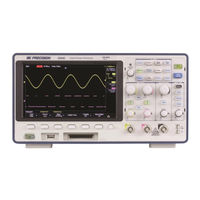
BK Precision 2544C-MSO User Manual (170 pages)
Digital Storage Oscilloscopes, Mixed Signal Oscilloscopes
Brand:
BK Precision
| Category:
Test Equipment
| Size: 6 MB
Table of Contents
Safety Summary
2
Compliance Statements
7
Safety Symbols
9
Notations
9
Table of Contents
10
General Information
16
Product Overview
16
Package Contents
16
Product Dimensions
17
Front Panel
18
Front Panel Description
18
Rear Panel
19
Back Panel Description
19
Display Information
20
User Interface Description
20
User Interface Functionality
21
Getting Started
24
Input Power Requirements
24
Line Voltage and Fuse Requirements
24
Preliminary Check
26
Security Lock
26
Verify AC Input Voltage
26
Connect Power
26
Adjust the Support Feet
27
Power-On Inspection
27
Self-Test
28
Self-Calibration
28
Check Model and Firmware Version
28
Connect the Probe
28
Probe Compensation
28
Probe Safety
29
Probe Attenuation
30
Main Functions and Operating Descriptions
31
Menu and Control Buttons
31
Connectors
33
Analog and External Trigger Connectors
33
Digital Connector
33
Front Panel USB Connector
34
Rear Panel Connectors
34
Vertical System
35
To Enable the Channel
35
Adjust the Vertical Scale
36
Adjust the Vertical Position
36
Specify Channel Coupling
36
Specify Bandwidth Limit
37
Specify Probe Attenuation Factor
37
Specify Channel Input Impedance
37
Specify the Amplitude Unit
38
Deskew
38
Inverting a Waveform
38
Horizontal System
39
Horizontal Scale Knob
39
Adjust Trigger Delay
40
Roll Mode
40
The Zoom Function
40
Run Control
42
Universal Knob
42
Adjust the Waveform Intensity
42
On-Line Help
43
Sample System Configuration
44
Run Control
44
Overview of Sampling
44
Sampling Theory
44
Sampling Rate
44
Oscilloscope Bandwidth and Sample Rate
46
Memory Depth
47
Sampling Mode
48
Waveform Interpolation Method
48
Acquisition Mode
51
Normal Mode (Default)
51
Peak Detect
51
Average
52
Eres (Enhanced Resolution)
54
Horizontal Format
55
Sequence Mode
56
Using the Sequence Mode
56
Replaying a Sequence of Captured Waveforms
57
Trigger
58
Overview of Triggering
59
Auto Setup
59
Setting the Trigger
59
Trigger Source
60
Trigger Mode
60
Trigger Level
61
Trigger Coupling
62
Trigger Hold off
62
Noise Rejection
63
Trigger Types
64
Edge Trigger
65
Slope Trigger
66
Pulse Trigger
68
Video Trigger
70
Window Trigger
73
Interval Trigger
75
Dropout Trigger
76
Runt Trigger
79
Pattern Trigger
81
Serial Trigger
83
Math Functions
93
Math Operations and Their Units
93
Addition and Subtraction
93
Multiplication and Division
94
FFT (Fast Fourier Transform)
94
Differentiation
96
Integration
97
Square Root
99
Cursors
100
Manual
100
Track
101
Auto Measurement
102
Type of Measurement
103
Voltage Measurements
103
Time Measurements
104
Delay Measurements
104
Statistics
105
Gate
105
To Clear Measurement Parameters
106
All Measure
106
Display Settings
106
Display Type
106
Color-Grade
108
Persistence
109
Clear the Display
109
Grid Type
110
Grid Brightness
110
Waveform Intensity
110
Transparency
110
Save and Recall
112
Save Type
112
Setups
112
Reference
112
Binary
112
BMP (Screen Picture)
112
Csv
112
Matlab
113
Setup Internal Save and Recall
113
Save Setup to Internal Memory
113
Load Setup from Internal Memory
113
External Save and Recall
113
External Save
113
Recall an External File
114
File Management
114
Create a New File or Folder
115
Delete a File or Folder
116
Rename a File or a Folder
116
Security Erase
116
Utility
117
View the System Status
117
Self Calibration
117
Sound
118
Language
118
Pass/Fail
119
Perform a Pass/Fail Test
119
Save and Recall Test Mask
121
I/O Remote Communication
121
Communicating Via USB
121
Communicating Via a LAN
121
Auxiliary Output
123
Update Firmware and Configuration
123
Perform a Self-Test
124
Screen Test
124
Keyboard Test
125
LED Test
126
Screen Saver
126
Option Management
127
Reference Waveforms
128
To Save a Reference Waveform to Internal Memory
129
To Display a Reference Waveform
129
To Adjust the Reference Waveform Position
129
To Clear the Reference Waveform
130
History Function
130
Default Setup
133
Serial Bus Decoding (DC2540C)
136
I2C Serial Decode
136
Setup for I2C Signals
136
SPI Serial Decode
138
Setup for SPI Signals
138
SPI Serial Decode
140
UART/RS232 Serial Decode
142
Setup for UART Signals
142
UART Serial Decode
143
CAN Serial Decode
144
Setup for CAN Signals
144
CAN Serial Decode
145
LIN Serial Decode
147
Setup for LIN Signals
147
Digital Channels (LA2540C + LP2540C)
149
Connecting Digital Probes to Device under Test
149
Acquiring Digital Waveforms
150
Displaying Digital Channels
150
Turning a Single Digital Channel on or off
152
Turning All Digital Channels on or off
152
Changing the Logic Threshold for Digital Channels
152
Repositioning a Digital Channel
153
Displaying Digital Channels as a Bus
153
Arbitrary Waveform Generator
155
Wave Types and Parameters
155
Sine Waveform
157
Square Waveform
157
Ramp Waveform
158
Pulse Waveform
158
DC Waveform
159
Noise Waveform
159
Cardiac Waveform
160
Gaus Pulse
160
Arbitrary Waveforms
161
Output Impedance
162
Set Default Values
162
AWG Self Cal
162
Specifications
164
Troubleshooting
166
Service Information
168
Limited One-Year Warranty
169
Advertisement
Advertisement
Related Products
BK Precision 2544C
BK Precision 2542B
BK Precision 2540B
BK Precision 2540B-GEN
BK Precision 2542B-GEN
BK Precision 2540C Series
BK Precision 2542C
BK Precision 2540C-MSO
BK Precision 2542C-MSO
BK Precision 2542
BK Precision Categories
Power Supply
Measuring Instruments
Test Equipment
Multimeter
Portable Generator
More BK Precision Manuals
Login
Sign In
OR
Sign in with Facebook
Sign in with Google
Upload manual
Upload from disk
Upload from URL