Sign In
Upload
Manuals
Brands
Binder Manuals
Accessories
KB 400 (E6)
Binder KB 400 (E6) Manuals
Manuals and User Guides for Binder KB 400 (E6). We have
2
Binder KB 400 (E6) manuals available for free PDF download: Operating Instructions Manual, Operating Manual
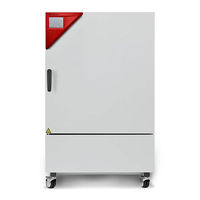
Binder KB 400 (E6) Operating Instructions Manual (149 pages)
Cooling Incubators
Brand:
Binder
| Category:
Accessories
| Size: 5 MB
Table of Contents
Table of Contents
2
1 Safety
6
Legal Considerations
6
Structure of the Safety Instructions
6
Signal Word Panel
6
Safety Alert Symbol
7
Pictograms
7
Word Message Panel Structure
8
Localization / Position of Safety Labels on the Chamber
8
Type Plate
9
General Safety Instructions on Installing and Operating the Chambers
10
Intended Use
12
Operating Instructions
12
Measures to Prevent Accidents
13
2 Chamber Description
14
Chamber Overview
15
Instrument Panel
16
Lateral Control Panel with Main Power Switch and Optional Equipment - KB 240 / 400 / 720 (E6)
17
Chamber Rear - KB 53 / 115 (E4)
18
3 Completeness of Delivery, Transportation, Storage, and Installation
19
Unpacking, and Checking Equipment and Completeness of Delivery
19
Guidelines for Safe Lifting and Transportation
20
Storage
20
Location of Installation and Ambient Conditions
21
4 Installation of the Equipment
22
Spacers for Wall Distance - KB 240 / 400 / 720 (E6)
22
Mounting the Flexible Tilt Protection Kit - KB 400 (E6)
23
Electrical Connection
24
5 Start up
25
6 Functional Overview of the T4.12 Chamber Controller
25
Menu Structure
26
General Menu
26
Quick Menu
28
User" Menu
28
Operating Modes
29
Activating the "Control Off" Mode or Change to "Fixed Value" Operating Mode
29
Performance During and after Power Failure
31
Information
32
7 Configuration of Optional Equipment
33
Turning on / off the Optional Interior Socket
33
Switching on or off the Optional Zero-Voltage Relay Control Outputs
34
Functional Test of the Optional Alarm Output
34
Switching on or off the Optional Object Temperature Display
35
RS 422 Address (with Optional RS 422 Interface)
35
8 Set-Point Entry in "Fixed Value" Operating Mode
36
Setting Ranges
36
Entering the Set-Points Via "Quick Menu
36
Entering the Set-Points Via General Menu
38
9 Time Programs
40
Starting and Running an Existing Time Program
42
Cancelling a Running Time Program
45
Creating a New Time Program
46
Section Handling
48
Temperature Setpoint
49
Section Duration
49
Repeating One or Several Sections Within a Time Program
50
Tolerance Range
51
Set-Point Ramp and Set-Point Step Modes
53
Switching on or off the Optional Zero-Voltage Relay Outputs
55
Calling up the Next Parameter
56
Saving the Time Program and Leaving the Program Editor
58
Program Interruption
60
Deleting a Time Program
61
10 Week Programs
62
Starting and Running an Existing Week Program
63
Cancelling a Running Week Program
66
Creating a New Week Program
67
Section Handling
69
Temperature Setpoint
70
Day of the Week
70
Time of the Day
71
Activity of the Shift-Point
72
Switching on or off the Optional Zero-Voltage Relay Outputs
72
Calling up the Next Parameter
73
Saving the Week Program and Leaving the Program Editor
75
Deleting a Week Program
76
11 Key Lock
77
Directly Activating the Key Lock Function
78
Automatic Key Lock
78
Changing the Password for Unlocking the Key Lock
80
12 General Controller Settings
81
Setup Wizard
82
Date and Time Settings
82
Selecting the Menu Language of the T4.12 Controller
84
Setting Display Brightness
84
Changing the Temperature Unit
85
Defining the Data Recording Rate
85
Factory Reset
86
Network Configuration
86
Display of the Entire Network Configuration
90
Display and Entry of the Chamber Configuration - for Service Purpose
90
13 Data Transfer Via Usb Interface
91
Exporting Data to USB Drive
91
Importing Data from USB Drive
92
14 Notifications and Alarms
93
Notifications Overview
93
Alarms Overview
93
Alarm Status
94
Confirming a "Set" Alarm
95
Alarm Configuration and Overview
96
List of Active Alarms
96
History - List of All Alarms
97
Activating, Deactivating, and Testing the Alarm Buzzer
98
Activating / Deactivating All Alarm Functions
98
15 Event List
99
16 Graphical Display of the Measured Values
100
Setting the Sampling Rate
100
Defining the Display Range
101
Selecting the Parameters
102
17 Temperature Safety Devices
103
Over Temperature Protective Device (Class 1)
103
Overtemperature Safety Controller (Temperature Safety Device Class 3.1)
103
Safety Controller Modes
103
Setting the Safety Controller
104
Over- and Undertemperature Safety Controller (Temperature Safety Device Class 3.3) (Option)
107
Safety Controller Modes
107
Setting the Over- and Undertemperature Safety Controller
108
18 Defrosting During Refrigerating Operation
111
19 Options
112
Communication Software APT-COM™ 3 Datacontrolsystem (Option)
112
RS RS 422 Interface (Option)
112
Data Logger Kit (Option)
112
Object Temperature Display with Flexible Pt 100 Temperature Sensor (Option)
113
Zero-Voltage Relay Alarm Output (May be Available Via BINDER INDIVIDUAL Customized Solutions)113
113
Analog Output for Temperature (Option)
115
Zero-Voltage Relay Control Outputs (May be Available Via BINDER INDIVIDUAL Customized Solution)
115
Water Protected Internal Socket (Option)
116
Interior Lighting
116
20 Maintenance, Cleaning, and Service
117
Maintenance Intervals, Service
117
Cleaning and Decontamination
118
Cleaning
118
Decontamination
119
Sending the Chamber Back to BINDER Gmbh
120
21 Disposal
121
Disposal of the Transport Packing
121
Decommissioning
121
Disposal of the Chamber in the Federal Republic of Germany
121
Disposal of the Chamber in the Member States of the EC Except for the Federal Republic of Germany
123
Disposal of the Chamber in Non-Member States of the EC
124
22 Troubleshooting
125
23 Technical Description
127
Factory Calibration and Adjustment
127
Over Current Protection
127
Definition of Usable Volume
128
Technical Data
129
Equipment and Options (Extract)
131
Spare Parts and Accessories (Extract)
132
KB 53 Dimensions
133
KB 115 Dimensions
134
KB 240 Dimensions
135
KB 400 Dimensions
136
KB 720 Dimensions
137
24 Certificates and Declarations of Conformity
138
EU Declaration of Conformity
138
Certificate for the GS Mark of Conformity of the "Deutsche Gesetzliche Unfallversicherung E.V." (German Social Accident Insurance) DGUV
140
25 Product Registration
142
26 Contamination Clearance Certificate
143
For Chambers Located Outside USA and Canada
143
For Chambers in USA and Canada
146
Advertisement
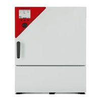
Binder KB 400 (E6) Operating Manual (147 pages)
Cooling Incubators with compressor technology and program control
Brand:
Binder
| Category:
Accessories
| Size: 8 MB
Table of Contents
Table of Contents
2
Safety
6
Personnel Qualification
6
Operating Manual
6
Legal Considerations
6
Intellectual Property
7
Structure of the Safety Instructions
7
Signal Word Panel
7
Safety Alert Symbol
8
Pictograms
8
Word Message Panel Structure
9
Localization / Position of Safety Labels on the Chamber
9
Type Plate
10
General Safety Instructions on Installing and Operating the Chambers
11
Intended Use
13
Foreseeable Misuse
14
Residual Risks
15
Operating Instructions
16
Measures to Prevent Accidents
16
Chamber Description
18
Chamber Overview
19
Instrument Panel
20
Lateral Control Panel with Main Power Switch and Optional Equipment - KB / KB-UL 240 / 400 / 720 (E6)
21
Chamber Rear - KB / KB-UL 53 / 115 (E4)
22
Completeness of Delivery, Transportation, Storage, and Installation
23
Unpacking, and Checking Equipment and Completeness of Delivery
23
Guidelines for Safe Lifting and Transportation
24
Storage
24
Location of Installation and Ambient Conditions
25
Installation of the Chamber
27
Spacers for Wall Distance - KB / KB-UL 240 / 400 / 720 (E6)
27
Mounting the Flexible Tilt Protection Kit
28
Electrical Connection
29
Start up
30
Functional Overview of the T4.12 Chamber Controller
30
Menu Structure
31
General Menu
31
Quick Menu
33
User" Menu
33
Operating Modes
34
Activating the "Control Off" Mode or Change to "Fixed Value" Operating Mode
34
Performance During and after Power Failure
36
Information
36
Configuration of Optional Equipment
37
Switching on or off the Optional Zero-Voltage Relay Control Outputs
38
Functional Test of the Optional Alarm Output
39
Switching on or off the Optional Object Temperature Display
39
Set-Point Entry in "Fixed Value" Operating Mode
40
Set-Point Ranges
40
Entering the Set-Points Via "Quick Menu
40
Entering the Set-Points Via General Menu
42
Time Programs
43
Starting and Running an Existing Time Program
45
Cancelling a Running Time Program
48
Creating a New Time Program
49
Section Handling
51
Temperature Setpoint
52
Section Duration
52
Repeating One or Several Sections Within a Time Program
53
Tolerance Range
54
Set-Point Ramp and Set-Point Step Modes
56
Switching on or off the Optional Zero-Voltage Relay Outputs
58
Calling up the Next Parameter
58
Saving the Time Program and Leaving the Program Editor
60
Program Interruption
61
Deleting a Time Program
63
Week Programs
64
Starting and Running an Existing Week Program
65
Cancelling a Running Week Program
67
Creating a New Week Program
68
Section Handling
70
Temperature Setpoint
71
Day of the Week
71
Time of the Day
72
Activity of the Shift-Point
73
Switching on or off the Optional Zero-Voltage Relay Outputs
73
Calling up the Next Parameter
74
Saving the Week Program and Leaving the Program Editor
76
Deleting a Week Program
77
Key Lock
78
Directly Activating the Key Lock Function
79
Automatic Key Lock
79
Changing the Password for Unlocking the Key Lock
81
General Controller Settings
82
Setup Wizard
83
Date and Time Settings
83
Selecting the Menu Language of the T4.12 Controller
85
Setting Display Brightness
85
Changing the Temperature Unit
86
Defining the Data Recording Rate
86
Factory Reset
87
Network Configuration
87
Display of the Entire Network Configuration
91
Display and Entry of the Chamber Configuration - for Service Purpose
91
Data Transfer Via Usb Interface
92
Exporting Data to USB Drive
92
Importing Data from USB Drive
93
Notifications and Alarms
94
Notifications Overview
94
Alarms Overview
94
Alarm Status
95
Confirming a "Set" Alarm
96
Alarm Configuration and Overview
97
List of Active Alarms
97
History - List of All Alarms
98
Activating, Deactivating, and Testing the Alarm Buzzer
99
Activating / Deactivating All Alarm Functions
99
Event List
100
Graphical Display of the Measured Values
101
Setting the Sampling Rate
101
Defining the Display Range
102
Selecting the Parameters
103
Temperature Safety Devices
103
Over Temperature Protective Device (Class 1)
103
Overtemperature Safety Controller (Temperature Safety Device Class 3.1)
103
Safety Controller Modes
104
Setting the Safety Controller
104
Over- and Undertemperature Safety Controller (Temperature Safety Device Class 3.3) (Option)
108
Safety Controller Modes
108
Setting the Over- and Undertemperature Safety Controller
109
Defrosting During Refrigerating Operation
112
Options
113
APT-COM™ 4 Multi Management Software (Option)
113
Data Logger Kit (Option)
113
Interior Lighting
113
Zero-Voltage Relay Alarm Output (Option)
113
Zero-Voltage Relay Control Outputs (May be Available Via BINDER INDIVIDUAL Customized Solution)
114
Object Temperature Display with Flexible Pt 100 Temperature Sensor (Option)
115
Cleaning and Decontamination
116
Cleaning
116
Decontamination / Chemical Disinfection
117
Maintenance and Service, Troubleshooting, Repair, Testing
119
General Information, Personnel Qualification
119
Maintenance Intervals, Service
119
Simple Troubleshooting
120
Sending the Chamber Back to BINDER Gmbh
123
Disposal
123
Disposal of the Transport Packing
123
Decommissioning
124
Disposal of the Chamber in the Federal Republic of Germany
124
Disposal of the Chamber in the Member States of the EU Except for the Federal Republic of Germany
125
Disposal of the Chamber in Non-Member States of the EU
126
Technical Description
127
Factory Calibration and Adjustment
127
Over Current Protection
127
Definition of Usable Volume
127
Technical Data
128
Equipment and Options (Extract)
130
Spare Parts and Accessories (Extract)
131
KB / KB-UL 53 Dimensions
132
KB / KB-UL 115 Dimensions
133
KB / KB-UL 240 Dimensions
134
KB / KB-UL 400 Dimensions
135
KB / KB-UL 720 Dimensions
136
Certificates and Declarations of Conformity
137
EU Declaration of Conformity
137
Certificate for the GS Mark of Conformity of the "Deutsche Gesetzliche Unfallversicherung E.V." (German Social Accident Insurance) DGUV
140
Contamination Clearance Certificate
142
For Chambers Located Outside USA and Canada
142
For Chambers in USA and Canada
145
Advertisement
Related Products
Binder KB 400-UL (E6)
Binder KB 400
Binder KB400-230V
Binder KB 400-UL
Binder KB400UL-120V
Binder KB 720 (E6)
Binder APT.line KB 115-UL
Binder KB-UL
Binder KB720UL-240V
Binder KB
Binder Categories
Climate chamber
Laboratory Equipment
Accessories
Oven
Farm Equipment
More Binder Manuals
Login
Sign In
OR
Sign in with Facebook
Sign in with Google
Upload manual
Upload from disk
Upload from URL