Sign In
Upload
Manuals
Brands
Binder Manuals
Laboratory Equipment
CB260-230V-O
Binder CB260-230V-O Manuals
Manuals and User Guides for Binder CB260-230V-O. We have
1
Binder CB260-230V-O manual available for free PDF download: Operating Manual
Binder CB260-230V-O Operating Manual (199 pages)
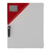
CO2 Incubator
Brand:
Binder
| Category:
Laboratory Equipment
| Size: 13 MB
Table of Contents
Table of Contents
2
Safety
8
Personnel Qualification
8
Operating Manual
8
Legal Considerations
8
Intellectual Property
9
Structure of the Safety Instructions
9
Signal Word Panel
9
Safety Alert Symbol
10
Pictograms
10
Word Message Panel Structure
11
Localization / Position of Safety Labels on the Chamber
11
Type Plate
12
General Safety Instructions on Installing and Operating the CO Incubator
13
Precautions When Working with Gases
15
Precautions When Handling Gas Cylinders
17
Intended Use
18
Foreseeable Misuse
19
Residual Risks
20
Operating Instructions
21
Measures to Prevent Accidents
22
CBF / CBF-UL : Resistance of the Humidity Sensor against Harmful Substances
23
Chamber Description
24
Chamber Overview
25
Inner Chamber
26
Control Panel on the Rear of the Chamber
27
Instrument Panel
28
Installation
28
Unpacking, and Checking Equipment and Completeness of Delivery
28
Guidelines for Safe Lifting and Transportation
29
Storage
29
Location of Installation and Ambient Conditions
30
Installation and Connections
33
Shelves
33
Permadry™ Water Pan
34
Connecting the O
35
Gas Connections
35
Sensor (Chamber with O 2 Control)
35
Connection of the CO Gas Cylinder
36
Connection of the O Gas Cylinder (Chamber with O Control with Optional Alternative Control Range 10 up to 95 Vol.-% O )
37
Connection of the N Gas Cylinder (Chamber with O Control)
38
Connecting the Gas Hose to the Chamber Rear (for CO )
39
Gas Cylinder Connection Kits (Option)
41
CBF / CBF-UL: Water Supply and Dehumidification
41
General Remarks on Water Supply
41
Water Supply
41
Dehumidification
42
Types of Suitable Water Quality
42
BINDER Pure Aqua Service (Option)
42
Water Supply Via Freshwater Bag (Standard)
43
Scope of Delivery
43
Installation and Connection of the Freshwater Bag
43
Refilling the Already Installed Freshwater Bag
44
Replacing the Tube Connectors for Freshwater Supply
45
Water Supply Via Prefilled Water Bottle (Optional Humidification Water Set)
46
Scope of Delivery
46
Installation, Connection and Change of the Prefilled Water Bottle
46
Water Supply Via Freshwater Can (Optional Water Container Set)
48
Scope of Delivery
49
Installation and Connection of the Freshwater Can (Optional Water Container Set)
49
Refilling the Freshwater Can
51
Electrical Connection
52
Divided Inner Door with Cell Therapy Compartmentation (Optional)
53
Special Model CBF 260 "Cell Therapy
53
Handling and Aligning the Divided Inner Door
54
Mounting the Partition Walls for Cell Therapy Compartmentation
55
Functional Overview of the Mb2 Chamber Controller
57
Operating Functions in Normal Display
58
Display Views: Normal Display, Program Display, Chart-Recorder Display
59
Controller Icons Overview
60
Operating Modes
62
Controller Menu Structure
63
Main Menu
64
Settings" Submenu
65
Service" Submenu
65
Principle of Controller Entries
66
Performance During and after Power Failures
66
Performance When Opening the Door
67
Start up
67
Turning on the Chamber
67
Controller Settings Upon Start up
68
Factory Settings
69
Equilibration Time
69
Operating the Duodoor™ Door Lock
70
Required Gas Supply for the Chamber with O
70
Hypoxic Control Range 0.2 Vol.-% up to 20 Vol.- % O (Regular)
70
Alternative Control Range 10 Vol.-% up to 95 Vol.-% (Available Via BINDER INDIVIDUAL Customized Solutions)
70
Control
70
Activating / Deactivating CO and Humidity Control
71
Control
71
CB / CB-UL: Humidity Control of the Permadry™ System
72
Set-Point Entry in "Fixed Value" Operating Mode
73
Set-Point Entry through the "Setpoints" Menu
74
Direct Setpoint Entry Via Normal Display
75
Special Controller Functions Via Operation Lines
76
Safety Instructions for Setting High Gas Concentrations
77
Timer Program: Stopwatch Function
78
Starting a Timer Program
78
Performance During Program Delay Time
78
Stopping a Running Timer Program
79
Pausing a Running Timer Program
79
Cancelling a Running Timer Program
79
Performance after the End of the Program
79
Time Programs
80
Starting an Existing Time Program
80
Performance During Program Delay Time
81
Stopping a Running Time Program
81
Pausing a Running Time Program
81
Cancelling a Running Time Program
81
Performance after the End of the Program
81
Creating a New Time Program
82
Program Editor: Program Management
82
Deleting a Time Program
83
Section Editor: Section Management
84
Add a New Program Section
85
Copy and Insert or Replace a Program Section
85
Deleting a Program Section
86
Value Entry for a Program Section
87
Section Duration
87
Set-Point Ramp and Set-Point Step
88
Special Controller Functions Via Operation Lines
90
Setpoint Entry
91
Tolerance Range
91
Repeating One or Several Sections Within a Time Program
92
Saving the Time Program
93
Week Programs
93
Starting an Existing Week Program
93
Cancelling a Running Week Program
94
Creating a New Week Program
94
Program Editor: Program Management
95
Deleting a Week Program
96
Section Editor: Section Management
97
Add a New Program Section
98
Copy and Insert or Replace a Program Section
98
Deleting a Program Section
99
Value Entry for a Program Section
99
Set-Point Ramp and Set-Point Step Modes
99
Weekday
100
Start Time
100
Setpoint Entry
101
Special Controller Functions Via Operation Lines
101
Notification and Alarm Functions
102
Notification and Alarm Messages Overview
102
Notifications
102
Alarm Messages
103
State of Alarm
105
Resetting an Alarm, List of Active Alarms
105
Activating / Deactivating the Audible Alarm (Alarm Buzzer)
106
Tolerance Range Settings and Alarm Delay Times
106
Zero-Voltage Relay Alarm Output
108
Temperature Safety Devices
109
Over Temperature Protective Device (Class 1)
109
Overtemperature Safety Controller Class 3.1
109
Safety Controller Modes
110
Setting the Safety Controller
110
Message and Measures in the State of Alarm
111
Function Check
111
User Management
112
Authorization Levels and Password Protection
112
Log in
115
Log out
116
User Change
116
Password Assignment and Password Change
117
Password Change
117
Deleting the Password for an Individual Authorization Level
119
New Password Assignment for "Service" or "Admin" Authorization Level When the Password Function was Deactivated
120
Activation Code
121
General Controller Settings
122
Selecting the Controller's Menu Language
122
Setting Date and Time
122
Selecting the Temperature Unit
124
Display Configuration
124
Adapting the Display Parameters
124
Touchscreen Calibration
125
Network and Communication
126
Serial RS485 Interface (Available Via BINDER INDIVIDUAL Customized Solutions)
126
Ethernet
127
Configuration
127
Display of MAC Address
128
Web Server
128
E-Mail
129
USB Menu: Data Transfer Via USB Interface
130
General Information
131
Service Contact Page
131
Current Operating Parameters
131
Event List
132
Technical Chamber Information
132
Chart Recorder Display
133
Views
133
Show and Hide Legend
133
Switch between Legend
133
Show and Hide Specific Indications
134
History Display
134
Setting the Parameters
137
Cbf / Cbf-Ul: Humidification System
138
Function of the Humidifying System
138
Function of the Dehumidifying System
139
Options
139
APT-COM™ 4 Multi Management Software (Option)
139
Silicone Access Ports 30 MM / 1.18 In, Closable from both Sides with Silicon Plugs (Option)
139
Quick Sample Access (Option)
140
Interior Socket 230V (Option, Available Via BINDER INDIVIDUAL Customized Solutions)
141
Analog Outputs for Temperature and CO (Option)
142
Data Logger Kits (Option)
143
Access Port for Extra-Low Voltage (Option)
143
BINDER Gas Supply Service - External Bottle Changer for CO
144
Stands
145
Stacking Stand (Option)
145
Base on Castors (Option)
145
Water Supply Sets (Optional for CBF / CBF-UL)
145
Tubular Bag Set (Option)
145
Humidification Water Set (Option)
145
Water Container Set (Option)
145
Reference Measurements
146
CO Reference Measuring
146
Measuring CO Concentration Indirectly Via the Ph of the Cell Medium
146
Measuring CO Directly Via Chemical Indicator Tubes
147
Measuring CO Directly with an Electronic Infrared Measuring Device
147
Temperature Reference Measurement
147
Avoiding Microbial Contamination
148
Cells and Media
148
Laboratory Conditions / Equipment Around the Incubator
148
Working and Behavior in the Lab
148
Chamber Design and Equipment of the CO Incubator
149
Handling the CO Incubator
150
Cleaning, Decontamination / Disinfection, and Sterilization
151
Cleaning
151
Decontamination / Chemical Disinfection of the Chamber
153
Disinfection of the CO
154
CBF / CBF-UL: Disinfection of Components of the Fresh Water Supply System
154
Sensor
154
Hot-Air Sterilization
155
Overview
155
Preparation for a Hot-Air Sterilization
156
Starting the Sterilization Cycle and Running the Hot-Air Sterilization
156
Prematurely Terminating the Sterilization Cycle
158
Prematurely Terminating the Sterilization Cycle after Less than 4 Hours: Ineffective Sterilization
158
Prematurely Terminating the Sterilization Cycle after more than 4 Hours, I.e., During the Cooling-Down Phase: Successful Sterilization
159
Completing the Entire Sterilization Cycle
160
Maintenance and Service, Troubleshooting, Repair, Testing
161
General Information, Personnel Qualification
161
CBF / CBF-UL: Replacing Components of the Humidifying / Dehumidifying System
162
Replacing the Silicone Tube of the Fresh Water Supply System
162
Replacing the Pump Head of the Fresh Water Supply System
162
Replacing the Gas Fine Filter (Sterile Filter) for Ambient Air
162
Replacing the CO
163
Und O 2 /N 2 Gas Inlet Fine Filters (Sterile Filters)
163
Replacing the CO Sensor
164
Maintenance Intervals, Service
165
Simple Troubleshooting
166
General
166
Heating
167
Gas Cylinder Pressure too Low
168
Gas Control
169
Sterilization
171
Humidity (CB / CB-UL)
171
Humidity (CBF / CBF-UL)
172
Controller
172
Open Door
173
Sending the Chamber Back to BINDER Gmbh
173
Disposal
174
Disposal of the Transport Packing
174
Outer Chamber Packing
174
Packing Inside the Chamber and Equipment
174
Decommissioning
175
Disposal of the Chamber in the Federal Republic of Germany
175
Disposal of the Chamber in the Member States of the EU Except for the Federal Republic of Germany
176
Disposal of the Chamber in Non-Member States of the EU
178
Technical Description
178
Factory Calibration and Adjustment
178
Over Current Protection
178
Definition of Usable Volume
179
Technical Data
179
Equipment and Options (Extract)
182
Accessories and Spare Parts (Extract)
183
Important Conversion Data for Non-SI Units
186
Conversion Table for Gas Inlet Pressures, Bar - Psi
186
Dimensions
187
Chamber Size 56
187
Chamber Size 170
188
Chamber Size 260
189
Certificates and Declarations of Conformity
190
EU Declaration of Conformity for CB
190
EU Declaration of Conformity for CBF
192
Contamination Clearance Certificate
194
For Chambers Located Outside the USA and Canada
194
For Chambers in the USA and Canada
197
Advertisement
Advertisement
Related Products
Binder CB 260
Binder CB260-230V
Binder CB 260-UL
Binder CB260-120V
Binder CB260-120V-O
Binder CB 220
Binder CB 220-UL
Binder CB 160
Binder CB56-230V-O
Binder CBF170-120V-O
Binder Categories
Climate chamber
Laboratory Equipment
Accessories
Oven
Farm Equipment
More Binder Manuals
Login
Sign In
OR
Sign in with Facebook
Sign in with Google
Upload manual
Upload from disk
Upload from URL