BEST ACCESS SYSTEMS B.A.S.I.S. V Manuals
Manuals and User Guides for BEST ACCESS SYSTEMS B.A.S.I.S. V. We have 2 BEST ACCESS SYSTEMS B.A.S.I.S. V manuals available for free PDF download: Service Manual, User Manual
BEST ACCESS SYSTEMS B.A.S.I.S. V Service Manual (290 pages)
Brand: BEST ACCESS SYSTEMS
|
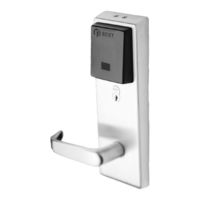
Category: Door locks
|
Size: 7 MB
Table of Contents
-
-
Figures
11 -
-
Introduction17
-
-
-
Unctions and25
-
-
-
Unctions and49
-
Levers65
-
Tandard and67
-
-
-
-
Reader Kits70
-
Battery Kits71
-
Screw Kits73
-
-
-
-
-
-
Core92
-
-
-
-
-
-
-
Exit Hardware144
-
Escutcheon144
-
-
-
S S O E P147
-
Primary Harness153
-
-
-
-
-
Primary Harness167
-
Sensor Harness167
-
Upgrade Cable169
-
-
Maintenance
207 -
Troubleshooting
227-
Troubleshooting231
Advertisement

BEST ACCESS SYSTEMS B.A.S.I.S. V User Manual (38 pages)
Brand: BEST ACCESS SYSTEMS
|
Category: Door locks
|
Size: 0 MB