Sign In
Upload
Manuals
Brands
Beckhoff Manuals
Control Unit
EP3314
Beckhoff EP3314 EtherCAT Box Manuals
Manuals and User Guides for Beckhoff EP3314 EtherCAT Box. We have
1
Beckhoff EP3314 EtherCAT Box manual available for free PDF download: Documentation
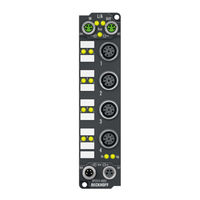
Beckhoff EP3314 Documentation (92 pages)
EtherCAT Box Modules for Pt100 (RTD) and for thermocouples
Brand:
Beckhoff
| Category:
Control Unit
| Size: 2.06 MB
Table of Contents
Table of Contents
3
1 Foreword
5
Notes on the Documentation
5
Safety Instructions
6
Documentation Issue Status
7
2 Ethercat Box
9
Ethercat Box - Introduction
9
Fig. 1 Ethercat Box Modules Within an Ethercat Network
9
Fig. 2 Ethercat Box with M8 Connections for Sensors/Actuators
10
Fig. 3 Ethercat Box with M12 Connections for Sensors/Actuators
10
Module Overview
11
3 Ep3204
12
Introduction
12
Fig. 4 EP3204-0002
12
Technical Data
13
Scope of Supply
14
Process Image
15
Fig. 5: RTD Rtdinputs Channel 1
15
4 Ep3314
16
Introduction
16
Fig. 6 EP3314-0002
16
Technical Data
17
Scope of Supply
19
Process Image
20
Fig. 7 TC Inputs Channel
20
5 Mounting and Connection
21
Mounting
21
Dimensions
21
Fig. 8 Dimensions
21
Fixing
22
Tightening Torques for Plug Connectors
22
Connection
23
Supply Voltages
23
Fig. 9 Connectors for Supply Voltages
23
Fig. 10 M8 Connector
23
Fig. 11 Status Leds for the Power Supply
24
Ethercat
25
Fig. 12 Ethercat Connector
25
Fig. 13 M8 Socket
25
Fig. 14 Ethercat Status Leds
26
Signal Connection
27
Fig. 15 Signal Connection - PT100 (RTD)
27
Fig. 16 Signal Connection - Thermocouple
28
Fig. 17 Status Leds at the Signal Connections
29
UL Requirements
30
Fig. 18 UL Label
30
ATEX Notes
31
ATEX - Special Conditions
31
BG2000 - Ethercat Box Protection Enclosures
32
Fig. 19 BG2000 - Putting the Cables
32
ATEX Documentation
33
Fig. 20 BG2000 - Fixing the Cables
33
Fig. 21 BG2000 - Mounting the Protection Enclosure
33
6 Commissioning/Configuration
34
Configuration in Twincat
34
EP3204 - Data Stream and Calculation of the Process Data
34
Vendor Calibration
34
Fig. 22 Resistance Measurement with a 4-Wire, 3-Wire and 2-Wire Connection Technique
34
Fig. 23 Data Flow: Resistance Measurement with a 2 and 4-Wire Connection Technique
35
Fig. 24 Resistance Measurement with a 4-Wire, 3-Wire and 2-Wire Connection Technique
36
Fig. 25 Data Flow: Resistance Measurement with a 3-Wire Connection Technique
37
User Calibration and Linearization
38
Fig. 26 Data Flow: User Compensation and Linearization
38
Scaling, Limits and Formatting
39
Fig. 27 Data Flow: User Scaling, Limit Evaluation, Error Bits and Formatting
39
Summary
40
Two-Point User Calibration
41
EP3204 - Object Overview
43
EP3204 - Object Description and Parameterization
49
Objects to be Parameterized During Commissioning
49
Objects for Regular Operation
54
Standard Objects (0X1000-0X1Fff)
55
Profile-Specific Objects (0X6000-0Xffff)
58
EP3314 - Object Overview
63
EP3314 - Object Description and Parameterization
70
Objects to be Parameterized During Commissioning
70
Objects for Regular Operation
76
Standard Objects (0X1000-0X1Fff)
76
Profile-Specific Objects (0X6000-0Xffff)
83
Restoring the Delivery State
88
Fig. 28 Selecting the Restore Default Parameters PDO
88
Fig. 29 Entering a Restore Value in the Set Value Dialog
88
7 Appendix
89
General Operating Conditions
89
Ethercat Box- / Ethercat P Box - Accessories
90
Support and Service
91
List of Illustrations
92
Advertisement
Advertisement
Related Products
Beckhoff EP3204
Beckhoff EP31 Series
Beckhoff EP3162
Beckhoff EP31 4 Series
Beckhoff EP3182
Beckhoff EP3174-0092
Beckhoff EP3184-0002
Beckhoff EP3184-1002
Beckhoff EP3174-0002
Beckhoff EPP3174
Beckhoff Categories
Touch terminals
Industrial PC
Control Unit
Touch Panel
Power Supply
More Beckhoff Manuals
Login
Sign In
OR
Sign in with Facebook
Sign in with Google
Upload manual
Upload from disk
Upload from URL