Sign In
Upload
Manuals
Brands
Beckhoff Manuals
Servo Drives
AX5911
Beckhoff AX5911 Manuals
Manuals and User Guides for Beckhoff AX5911. We have
1
Beckhoff AX5911 manual available for free PDF download: Start-Up
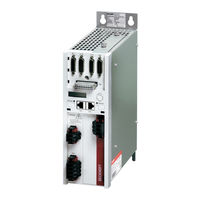
Beckhoff AX5911 Start-Up (44 pages)
Servo Drive 1.5 A - 40 A
Brand:
Beckhoff
| Category:
Servo Drives
| Size: 4 MB
Table of Contents
Table of Contents
4
Foreword
6
Notes on the Documentation
6
Disclaimer
6
Trademarks
6
Patent Pending
6
Copyright
7
Documentation Issue Status
7
Appropriate Use
8
Documented Servo Drives
8
Safety
10
General Safety Instructions
10
Safety Rules
10
Disclaimer
10
Description of Safety Symbols
10
Personnel Qualification
11
Special Safety Instructions for AX5000
11
Guidelines and Standards
13
CE Conformity
13
Electromagnetic Compatibility
13
UL-Listing
14
UL-Specific Chapter Changes
14
UL-Specific Chapter
14
UL-Specific Notes
15
Electrical Isolation According to en 50178 / VDE 160
15
Product Description
16
Type Code
16
Scope of Supply
16
Standard Scope of Supply
16
Accessories
17
Name Plate
17
Technical Data
18
Permissible Ambient and Operating Conditions
18
Electrical Data - Single-Channel Servo Drive (Ax51Xx)
18
Single-Phase Connection
18
Three-Phase Connection
19
Electrical Data - Two-Channel Servo Drive (Ax52Xx)
20
Single-Phase Connection
20
Three-Phase Connection
20
Mechanical Data (Single-Channel Servo Drive)
21
Mechanical Data (Two-Channel Servo Drive)
21
General Overview (AX5101 - AX5112 and Ax520X)
22
General Overview (AX5118, AX5125 und AX5140)
23
Overview of Connectors/Terminal Points
24
X01 - Wide Voltage Input
24
X02 - DC Link (AX5101 - AX5125 und Ax520X)
24
X02 - DC Link (Only AX5140)
24
X03 - 24 VDC Supply
24
X04, X05 - Ethercat Connection
25
X06 - Digital I/Os
25
X11 (Channel A) , X21 (Channel B) - Feedback, High-Resolution
26
X12 (Channel A) , X22 (Channel B) - Resolver/Hall
26
X13 (Channel A) , X23 (Channel B) - Motor Connection (Power)
27
X13 - Motor Connection (Power - Only AX5140)
27
X14 (Channel A), X24 (Channel B) - Motor Brake, Thermal Contact
27
X07 - Internal and External Brake Resistor
28
Dimensions
29
Installation
31
Mechanical Installation
31
Installation in the Control Cabinet
31
Installation Example - AX5101-AX5112 and AX5201-AX5206
32
Installation Example - AX5118, AX5125 and AX5140
32
Electrical Installation
33
Mains Supply Connection (X01)
34
External Protection for Individual Devices, CE-Compliant
34
Internal Protection, CE-Compliant
34
External Protection, UL-Compliant
35
Internal Protection, UL-Compliant
35
External Drive System Protection
35
VDC - Supply Network Connection (X03)
36
Connection of Several Servo Drives to Form a Drive System
36
Connection Example - Module AX5901 and AX5911 (AX Bridge)
37
Connection Example - Wiring in Series Without AX Bridge
38
Configuration Example
39
Important Information for Commissioning
40
Project Planning - Important Information
41
Drive Train Design
41
Energy Management
41
Control Quality, Mass Inertia Ratio and Load Connection
41
EMC, Earthing, Screen Connection and Potential
42
Control Cabinet
42
Motors and Cables at Servo Drives up to 25A
42
Appendix
43
Support and Service
43
Beckhoff's Branch Offices and Representatives
43
Beckhoff Headquarters
43
Beckhoff Support
43
Beckhoff Service
43
Advertisement
Advertisement
Related Products
Beckhoff AX5901
Beckhoff AX5101
Beckhoff AX5125
Beckhoff AX5140
Beckhoff AX5172
Beckhoff AX5190
Beckhoff AX5191
Beckhoff AX5160
Beckhoff AX520 Series
Beckhoff AX5203-0000
Beckhoff Categories
Touch terminals
Industrial PC
Control Unit
Industrial Equipment
Power Supply
More Beckhoff Manuals
Login
Sign In
OR
Sign in with Facebook
Sign in with Google
Upload manual
Upload from disk
Upload from URL