Sign In
Upload
Manuals
Brands
Becker Manuals
Transceiver
6200 Series
Becker 6200 Series Manuals
Manuals and User Guides for Becker 6200 Series. We have
1
Becker 6200 Series manual available for free PDF download: Installation And Operation Manual
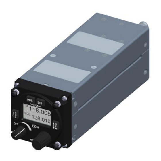
Becker 6200 Series Installation And Operation Manual (142 pages)
VHF-Transceivers
Brand:
Becker
| Category:
Transceiver
| Size: 3.19 MB
Table of Contents
Table of Contents
5
1 General Description
13
Introduction
14
Purpose of Equipment
15
General Notices
15
1.4 Variants Overview
16
Software Status
18
Short Description
19
Figure 1: Example: Device Combinations
19
Figure 2: AR6201, AR6211 Single Block Transceiver
20
Figure 3: AR6203, AR6213 Single Block Transceiver
20
Figure 4: RT6201, RT6211 Remote-Controlled Transceiver
21
Figure 5: RCU6201, RCU6211 Remote Control Unit
21
1.5 Scope of Functionality
22
Frequency Indication
22
Audio Outputs
22
Mike Inputs
22
AF Auxiliary Input
22
Sidetone
23
Squelch Operation
23
Memory Channels
23
Scan Mode
23
Illumination
23
LOW BATT Indication
23
Emergency Operation
23
Built-In Tests
23
Tandem Operation
24
Intercom Operation
24
Configuration Setup
24
Service Mode
24
Safety-Conscious Utilization
25
Restriction for Use
25
1.8 Technical Data
26
General Characteristics
26
Typical Power Consumption
27
Receiver Data AR62XX, RT62X1
27
Transmitter Data AR62XX, RT62X1
28
Emergency Operation
29
Dimensions & Weight
29
Software
30
Hardware
30
Continued Airworthiness
30
Environmental Conditions AR62X1-(X1X), RT62X1-(X1X)
31
Environmental Conditions AR62X1-(X2X), RT62X1-(X2X)
32
Environmental Conditions AR62X3-()
33
Environmental Conditions RCU62X1-()
35
Certifications
36
1.9 Order Code
40
Devices 62XX Series
40
Accessories
41
Spare Parts
42
Documentation
42
2 Installation
43
Packaging, Transport, Storage
44
Device Assignment
45
Scope of Delivery
45
State of Delivery
45
Additional Required Equipment
45
Registration of the Device
45
Type Plate
46
Software/Firmware Status - Functionality
46
Figure 6: Type Plate (Example)
46
Installation Requirements
47
Installation in the Avionic Compartment
48
Figure 7: RT62X1, MK6201-(10) Installation
48
Cockpit Panel Installation
49
Rear Panel Installation
49
Figure 8: MK6403-1: Cockpit Panel Installation
49
Figure 9: AR62X1, RCU62X1 (Front View)
49
Figure 10: Drilling Template -Rear-Panel Installation
49
Dimensions
50
Ar6201, Ar6211
50
Figure 11: Dimensions - AR6201, AR6211
50
Ar6203, Ar6213
51
Figure 12: Dimensions - AR6203, AR6213
51
Rcu62X1
52
Figure 13: Dimensions - RCU62X1
52
Rt62X1
53
Figure 14: Dimensions - RT62X1
53
RT62X1 with MK6201
54
Figure 15: Dimensions - RT62X1 with Mounting Kit MK6201
54
Mounting Kit - MK6201
55
Figure 16: Dimensions - Mounting Kit MK6201 (for RT62X1)
55
Mounting Kit - MK6403-1
56
Figure 17: Dimensions - Mounting Kit MK6403-1 (for AR62X3)
56
2.5 Connector Pin Assignments
57
Device Connectors (AR62XX, RT62X1)
57
Antenna Connector (AR62XX, RT62X1)
57
Grounding Bolt (AR62XX, RT62X1)
57
Figure 18: AR62X1, RT62X1 - Connector Layout
57
Figure 19: AR62X3 - Connector Layout
57
Inputs / Outputs (AR62XX, RT62X1)
60
Device Connector (RCU62X1)
64
Figure 20: RCU62X1 - Connector Layout
64
Inputs / Outputs (RCU62X1)
65
Installation and Configuration
66
General Requirements
66
Customized Applications
66
Antenna Installation
66
Configuration Setup
69
Configuration Interface
69
Start Configuration Setup
69
Figure 21: "PASSWORD
69
Figure 22: "DECIVE INFO
69
Volume Adjustment (VU Meter)
70
Device Info
71
Dimming, Brightness
72
Illumination Curve
73
Memory Options
74
Modification, Battery
74
Configuration
75
Auxiliary Audio Input
76
In/Out Cfg1
76
In/Out Cfg2
78
Standard Microphone 1
79
Standard Microphone 2
80
Standard Microphone 3
81
Dynamic Microphone
82
Speaker
82
Squelch
83
Scan Hold Time
83
Sidetone
83
Erase Memory
84
Fail List
85
Recall Default Settings
85
Factory Default Settings
86
Aircraft Wiring
88
Electrical Bonding and Grounding
88
Single Seat Glider
88
Figure 23: Wiring - Single Seat Glider
89
Figure 24: Wiring - Single Seat Glider 5-Pol DIN Jack
90
Installation with RT62X1 and RCU62X1
91
Figure 25: Wiring - Installation with RT62X1 and RCU62X1
91
Twin Seat with RT62X1 (Tandem-Installation)
92
Figure 26: Wiring - Twin Seat with RT62X1 (Tandem-Installation)
93
Twin Seat Motor Glider
94
Figure 27: Wiring - Twin Seat Motor Glider
95
General Aviation (GA) Aircraft
96
Figure 28: Wiring - General Aviation Aircraft (with Standard Hand Mikes, Earphones and Speaker)
97
Individual Dual Headset Installation (Two IC Circuits)
98
Figure 29: Wiring - Individual Dual Headset Installation (Two IC Circuits)
99
Twin Seat with AR62XX (Tandem-Installation)
100
Figure 30: Wiring - Twin Seat with AR62XX (Tandem-Installation)
101
Four Seat Installation (no Tandem)
102
Figure 31: Wiring - Four Seat Installation (no Tandem)
103
Installation in Aircraft with Intercom System
104
Figure 32: Wiring - Aircraft with Intercom System (Unbalanced)
105
Figure 33: Wiring - Aircraft with Intercom System (Balanced)
106
Recommendation for the Installation of Two Transceivers in One Aircraft
107
Cable Harness
111
Figure 34: Cable Harness 1K065
112
Retrofitting - AR4201 with AR62X1
113
Wiring AR4201 - AR62X1
113
Dynamic Microphone Input
114
Figure 35: AR62X1 with Wiring Interface for AR4201
114
Figure 36: Modified Dynamic Microphone Wiring for AR62X1
114
Temperature Sensor
115
RS232 Interface
115
Afcu/Agc/Afwb
115
CPIN (if Installed)
115
Ar4201) - Pwr_Eval (Ar62X1)
115
Post Installation Check
116
Mechanical Installation and Wiring Check
116
Power Supply
116
Receiver / Transmitter Operation
116
Antenna Check
116
Interference Check
117
Flight Test Check
118
Error / Failure Indication
118
Troubleshooting
119
3 Operation
121
General
121
Registration of the Device
121
In this Chapter You Can Read About: 3.1 General
121
Device Description
123
Device Assignment
123
Packing, Transport, Storage
123
Scope of Delivery
123
State of Delivery
123
Type Plate
123
Controls and Indications
124
Figure 37: Controls and Indicators
124
User Interface
124
Start-Up
125
Symbols on the Display
125
Receive Mode
126
Transmit Mode
126
Frequency Selection Modes
127
Standard Mode
128
Direct Tune Mode
129
Channel Mode
130
Frequency Storage Functions
131
Select Channels
131
Store
132
Automatic Storage Function
133
Label (Identifier) Data
133
Delete Data
133
Scan Mode
134
Squelch (SQL)
134
RX Field Strength Indication
135
Channel Spacing
135
Auxiliary Audio Input (AUX INPUT)
135
Intercom Operation
136
Pilot Circuit and Passenger Circuit
136
Intercom Operation Started with VOX
136
Intercom Operation Started with an Intercom Switch
137
VOX & Speaker Operation
137
Menus
137
User Menu
138
Intercom Menu
139
Read out and Reset Error/Failure Flags
140
Warning and Failure Indications
140
Contact Data
141
4 Index
142
Advertisement
Advertisement
Related Products
Becker Beck-O-Tronic 6
Becker Series
Becker 0622.834-923
Becker 0622.842-923
Becker 0637.289-923
Becker 0637.300-910
Becker 0638.463-923
Becker 0638.471-923
Becker 0638.481-923
Becker 0638.498-923
Becker Categories
Water Pump
Transmitter
DC Drives
Air Compressor
GPS
More Becker Manuals
Login
Sign In
OR
Sign in with Facebook
Sign in with Google
Upload manual
Upload from disk
Upload from URL