Sign In
Upload
Manuals
Brands
BeagleBone Manuals
Motherboard
BBONEBLK_SRM
BeagleBone BBONEBLK_SRM Development Board Manuals
Manuals and User Guides for BeagleBone BBONEBLK_SRM Development Board. We have
1
BeagleBone BBONEBLK_SRM Development Board manual available for free PDF download: Reference Manual
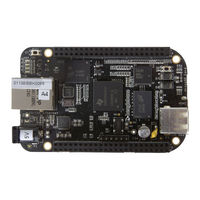
BeagleBone BBONEBLK_SRM Reference Manual (108 pages)
BeagleBone Black System
Brand:
BeagleBone
| Category:
Motherboard
| Size: 3 MB
Table of Contents
Table of Contents
7
Figures
9
Tables
11
1 Introduction
12
2 Change History
12
Document Change History
12
Board Changes
12
Rev A5B
12
Table 1. Change History
12
3 Connecting up Your Beaglebone Black
13
What's in the Box
13
Figure 1. in the Box
13
Main Connection Scenarios
14
Tethered to a PC
14
Figure 2. Tethered Configuration
14
Connect the Cable to the Board
15
Figure 3. USB Connection to the Board
15
Figure 4. Board Power LED
15
Accessing the Board as a Storage Drive
16
Figure 5. Board Boot Status
16
Standalone W/Display and Keyboard/Mouse
17
Required Accessories
17
Figure 6. Desktop Configuration
17
Connecting up the Board
18
Figure 7. Connect Microhdmi Cable to the Monitor
18
Figure 8. DVI-D to HDMI Adapter
18
Figure 9. Wireless Keyboard and Mouse Combo
19
Figure 10. Connect Keyboard and Mouse Receiver to the Board
19
Figure 11. Keyboard and Mouse Hubs
19
Apply Power
20
Figure 12. Ethernet Cable Connection
20
Figure 13. External DC Power
20
Figure 14. Connect Microhdmi Cable to the Board
21
Figure 15. Board Boot Status
22
Figure 16. Desktop Screen
23
4 Beaglebone Black Overview
24
Beaglebone Compatibility
25
Beaglebone Black Features and Specification
26
Table 2. Beaglebone Black Features
26
Board Component Locations
27
Connectors, Leds, and Switches
27
Figure 17. Connectors, Leds and Switches
27
Key Components
28
Figure 18. Key Components
28
5 Beaglebone Black High Level Specification
29
Block Diagram
29
Figure 19. Beaglebone Black Key Components
29
Processor
30
Memory
30
512Mb Ddr3L
30
32Kb Eeprom
30
2GB Embedded MMC
30
Microsd Connector
30
Boot Modes
31
Power Management
31
Pc Usb Interface
32
Serial Debug Port
32
Usb1 Host Port
32
Power Sources
32
Reset Button
33
Power Button
33
Indicators
33
Cti Jtag Header
33
Hdmi Interface
34
Cape Board Support
34
6 Detailed Hardware Design
35
Figure 20. Beaglebone Black Block Diagram
35
Power Section
36
Tps65217C Pmic
36
Figure 21. High Level Power Block Diagram
36
Figure 22. TPS65217C Block Diagram
37
DC Input
38
Figure 23. TPS65217 DC Connection
38
Figure 24. USB Power Connections
39
Table 3. Beaglebone Black Battery Pins
40
Power Button
40
Table 4. Beaglebone Black Power Consumption(Ma@5V)
41
Power Consumption
41
Figure 25. Power Rails
43
Figure 26. Power Rail Power up Sequencing
45
Figure 27. TPS6517C Power Sequencing Timing
45
Figure 28. Power Processor Interfaces
46
Power LED
46
Processor Control Interface
47
Figure 29. Sitara XAM3359AZCZ Block Diagram
48
S Itara Xam3359Azcz100 P Rocessor
48
Table 5. Processor Features
49
High Level Features
49
Ddr3L M Emory
50
Figure 30. DDR3L Memory Design
51
Figure 31. DDR3L VREF Design
52
Power Rails
52
Emmc Device
53
Figure 32. Emmc Memory Design
54
Table 6. Emmc Boot Pins
54
Emmc Circuit Design
54
Figure 33. Usd Design
55
Figure 34. User Leds
56
Table 7. User LED Control Signals/Pins
56
Figure 35. Processor Boot Configuration Design
57
REF: BBONEBLK_SRM Beaglebone Black System Rev A5.2
57
B Oot C Onfiguration
57
Figure 36. Processor Boot Configuration
58
Default Boot Options
58
Figure 37. Ethernet Processor Interface
59
E Thernet
59
Figure 38. Ethernet Connector Interface
60
Figure 39. Ethernet PHY, Power, Reset, and Clocks
61
Figure 40. Ethernet PHY Mode Pins
62
LAN8710A Mode Pins
62
Table 8. HDMI Supported Monitor Resolutions
63
REF: BBONEBLK_SRM Beaglebone Black System Rev A5.2
64
Figure 41. HDMI Framer Processor Interface
64
Table 9. TDA19988 I2C Address
65
HDMI Control Processor Interface
65
Figure 42. HDMI Power Connections
66
Figure 43. Connector Interface Circuitry
67
HDMI Connector Interface
67
Figure 44. Expansion Connector Location
68
Connector P8
69
Table 10. Expansion Header P8 Pinout
70
Connector P9
71
Table 11. Expansion Header P9 Pinout
72
Figure 45. 5VDC Power Jack
73
Figure 46. USB Client Connector
74
Figure 47. USB Host Connector
75
Figure 48. Serial Debug Header
76
Figure 49. FTDI USB to Serial Adapter
76
Figure 50. HDMI Connector
78
Figure 51. HDMI Connector
78
7 0 Connectors
69
Hdmi
78
Figure 52. Usd Connector
79
Micro Sd
79
E Thernet
80
Figure 53. Ethernet Connector
80
Cape Board Support
81
Beagleboneblack Cape Compatibility
82
LCD Pins
82
Table 12. P8 LCD Conflict Pins
82
Emmc Pins
83
Table 13. P8 Emmc Conflict Pins
83
Eeprom
84
Figure 54. Expansion Board EEPROM Without Write Protect
84
EEPROM Address
85
EEPROM Write Protect
85
I2C Bus
85
Figure 55. Expansion Board EEPROM Write Protect
86
EEPROM Data Format
87
Table 14. Expansion Board EEPROM
87
Pin Usage
88
Table 15. EEPROM Pin Usage
89
Pin Usage Consideration
92
Boot Pins
92
Figure 56. Expansion Boot Pins
92
Expansion Connectors
93
Non-Stacking Headers-Single Cape
93
Figure 57. Single Expansion Connector
93
Main Expansion Headers-Stacking
94
Figure 58. Single Cape Expansion Connector
94
Figure 59. Expansion Connector
94
Table 16. Single Cape Connectors
94
Stacked Capes W/Signal Stealing
95
Figure 60. Stacked Cape Expansion Connector
95
Table 17. Stacked Cape Connectors
95
Retention Force
96
Beaglebone Black Female Connectors
96
Figure 61. Stacked W/Signal Stealing Expansion Connector
96
Figure 62. Connector Pin Insertion Depth
96
Signal Usage
97
Cape Power
97
Main Board Power
97
Table 18. Expansion Voltages
97
Expansion Board External Power
98
Mechanical
98
Standard Cape Size
98
Extended Cape Size
99
Figure 63. Cape Board Dimensions
99
Enclosures
100
9 Beaglebone Black Mechanical
101
Dimensions and Weight
101
Silkscreen and Component Locations
102
Figure 64. Board Dimensions
102
Figure 65. Component Side Silkscreen
103
Figure 66. Component Side Silkscreen
104
10 0 Pictures
105
Figure 67. Top Side
105
Figure 68. Bottom Side
106
11 0 Support Information
107
Hardware Design
107
Software Updates
107
Rma Support
108
Figure 69. Bottom Side
108
Advertisement
Advertisement
Related Products
BeagleBone Black
BeagleBone A3
BeagleBone A4
BeagleBone A5
BeagleBone A6
BeagleBone RS232 Cape
BeagleBone Categories
Computer Hardware
Motherboard
More BeagleBone Manuals
Login
Sign In
OR
Sign in with Facebook
Sign in with Google
Upload manual
Upload from disk
Upload from URL