Sign In
Upload
Manuals
Brands
Basler Manuals
Power distribution unit
BE1-CDS240
User Manuals: Basler BE1-CDS240 Distribution Box
Manuals and User Guides for Basler BE1-CDS240 Distribution Box. We have
1
Basler BE1-CDS240 Distribution Box manual available for free PDF download: Instruction Manual
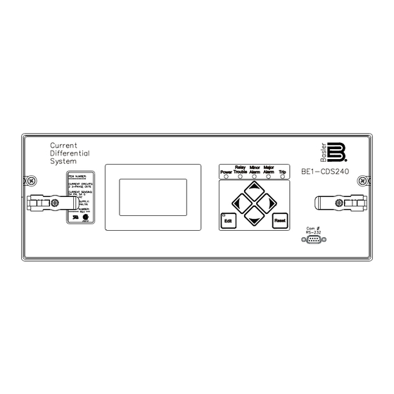
Basler BE1-CDS240 Instruction Manual (580 pages)
Current Differential Protection System
Brand:
Basler
| Category:
Power distribution unit
| Size: 15 MB
Table of Contents
Table of Contents
7
Revision History
5
Section 1 General Information
9
I/O Functions
12
Protection and Control Functions
13
Metering Functions
14
Bestlogic Programmable Logic
16
Communication Ports
16
Installation
17
Differential Protection Application Considerations
18
Problem 2: Measured Current Magnitude Mismatch
19
Problem 4: Phase Angle Shift
20
Figure 1-6. Three-Phase Connections, Delta-Wye Configuration, Internal Phase Compensation
23
Problem 5: Zero-Sequence Current Sources Within the Zone of Protection
23
Figure 1-7. Traditional Zero-Sequence Trap for Application with Ground Banks
24
Problem 6: Transformer Energization Inrush and Overexcitation
25
Model and Style Number Description
26
Figure 1-8. Style Number Identification Chart
27
Operational Specifications
27
Calculated Values and Accuracy
28
Figure 1-9. Typical 87 Response Characteristic Curves
29
ND Neutral Differential Function
30
Time Overcurrent Functions
31
Equation 1-1. Time to Trip
32
Equation 1-2. Time to Reset
32
Phase Undervoltage Function (27P/127P)
32
Phase Overvoltage Function (59P/159P)
33
General Purpose Timers (62, 162, 262, 362)
34
Analog to Digital Converter
35
Irig
36
Surge Withstand Capability
36
Table 1-1. Control Input Burden
36
C.S.A. Certification
37
Electrostatic Discharge (ESD)
37
Environment
37
GOST-R Certification
37
Radio Frequency Interference (RFI)
37
Shock
37
UL Recognition
37
Vibration
37
Section 2 Quick Start
39
Bestlogic
41
Characteristics of Protection and Control Elements
42
Element Logic Settings
43
Output Logic Settings
43
General
41
About this Manual
41
Section 2 Quick Start
41
User Interfaces
43
Front Panel HMI
43
ASCII Command Communications
44
BESTCOMS for BE1-CDS240, Graphical User Interface
45
Getting Started
46
Connections
46
Entering Test Settings
46
Checking the State of Inputs
47
Testing
47
Faq/Troubleshooting
47
Frequently Asked Questions (Faqs)
47
Section 3 • Input and Output Functions
51
Section 3 Input and Output Functions
51
Section 3 • Input and Output Functions
53
General
53
Power System Inputs
53
Compensated Restraint and Operate Currents for Differential Protection
53
Current Measurement Functions
53
Current Measurements
53
Fast-Dropout Current Detector
53
Neutral and Negative-Sequence Current Measurement
53
Virtual Circuit Measurement Functions
53
Frequency Compensation
54
Frequency Measurement
54
Nominal Frequency
54
Voltage Measurement
54
Voltage Measurement Functions
54
VT Connections
54
Zero-Sequence (V )Voltage
54
Power Measurement
55
Measurement Functions Setup
56
Power System / VT Setup
56
CT Setup
58
Transformer Setup
59
IEC Transformer Setup
66
Contact Sensing Inputs
67
Digital Input Conditioning Function
68
Setting the Digital Input Conditioning Function
68
Retrieving Input Status Information from the Relay
69
Outputs
69
Hardware Outputs and Virtual Outputs
69
Programmable Hold Timer
70
Relay Trouble Alarm Disable
70
Retrieving Output Status
70
Enabling Logic Override Control
71
Output Logic Override Control
71
Pulsing an Output Contact
71
Holding an Output Contact Open or Closed
72
Returning an Output Contact to Logic Control
72
Retrieving Output Logic Override Status
73
Section 4 Protection and Control
75
General
79
Section 4 Protection and Control
79
Setting Groups
79
Bestlogic Settings for Setting Group Control
80
Operating Settings for Setting Group Control
83
Logic Override of the Setting Group Control Function
86
Retrieving Setting Group Control Status from the Relay
87
Differential Protection
87
87 - Phase Differential Protection
87
Bestlogic Settings for Phase Differential
90
Tap Compensation Settings for Phase Differential
91
Operating Settings for Phase Differential
93
Retrieving Phase Differential Status from the Relay
94
Virtual Restraint Element
94
87ND - Neutral Differential Protection
96
Bestlogic Settings for Neutral Differential
98
Auto-Tap Compensation Settings for Neutral Differential
99
Operating Settings for Neutral Differential
99
Retrieving Neutral Differential Status from the Relay
101
Overcurrent Protection
101
50T - Instantaneous Overcurrent Protection with Settable Time Delay
101
Bestlogic Settings for Instantaneous Overcurrent
102
Operating Settings for Instantaneous Overcurrent
103
Retrieving Instantaneous Overcurrent Status from the Relay
105
51 - Time Overcurrent Protection
105
Bestlogic Settings for Time Overcurrent
106
Operating Settings for Time Overcurrent
107
Retrieving Time Overcurrent Status from the Relay
108
Voltage Restraint/Control for Time Overcurrent Protection
108
Operating Settings for Voltage Restraint/Control for Time Overcurrent
110
Programmable Curves
110
46 Curve
111
Setting Programmable Curves
111
Negative-Sequence Overcurrent Protection
112
Pickup Settings for Negative-Sequence Overcurrent
112
Coordination Settings for Negative-Sequence Overcurrent
113
Delta/Wye Transformer Application
113
Voltage Protection
113
24 - Volts Per Hertz Overexcitation Protection
113
Theory of Operation for Volts Per Hertz Overexcitation
114
Bestlogic Settings for Volts Per Hertz Overexcitation
115
Operating Settings for Volts Per Hertz Overexcitation
116
Programmable Alarm for Volts Per Hertz Overexcitation
117
Settings Example for Volts Per Hertz Overexcitation
117
Retrieving Volts Per Hertz Overexcitation Status from the Relay
120
27P/59P - Phase Undervoltage/Overvoltage Protection
120
Bestlogic Settings for Phase Undervoltage/Overvoltage
120
Operating Settings for Phase Undervoltage/Overvoltage
122
Retrieving Phase Undervoltage/Overvoltage Status from the Relay
123
59X - Auxiliary Overvoltage Protection
123
Bestlogic Settings for Auxiliary Overvoltage
124
Operating Settings for Auxiliary Overvoltage
125
Retrieving Auxiliary Overvoltage Status from the Relay
126
47 - Negative-Sequence Overvoltage Protection
126
Bestlogic Settings for Negative-Sequence Overvoltage
127
Operating Settings for Negative-Sequence Overvoltage
128
Retrieving Negative-Sequence Overvoltage Status from the Relay
129
Frequency Protection
129
81 - Over/Underfrequency Protection
129
Bestlogic Settings for Over/Underfrequency
130
Operating Settings for Over/Underfrequency
131
Retrieving Over/Underfrequency Status from the Relay
132
Breaker Failure Protection
133
50BF - Breaker Failure Protection
133
Bestlogic Settings for Breaker Failure
134
Operating Settings for Breaker Failure
135
Retrieving Breaker Failure Status from the Relay
136
Logic Timers
136
62 - General Purpose Logic Timers
136
Mode 1, PU/DO (Pickup/Dropout Timer)
137
Mode 2, One-Shot Nonretriggerable Timer
138
Mode 3, One-Shot Retriggerable Timer
138
Mode 4, Oscillator
138
Mode 5, Integrating Timer
139
Mode 6, Latch
139
Bestlogic Settings for General Purpose Logic Timers
140
Operating Settings for General Purpose Logic Timers
141
Retrieving General Purpose Logic Timers Status from the Relay
142
Voltage Transformer Fuse Loss Detection
142
60FL - Fuse Loss Detection
142
Fuse Loss Detection Blocking Settings
143
Retrieving Fuse Loss Detection Status from the Relay
145
Virtual Switches
145
43 - Virtual Selector Switches
145
Bestlogic Settings for Virtual Selector Switches
146
Select before Operate Control of Virtual Selector Switches
147
Retrieving Virtual Selector Switches Status from the Relay
148
101 - Virtual Breaker Control Switches
148
Bestlogic Settings for Virtual Breaker Control Switches
148
Select before Operate Control of Virtual Breaker Control Switches
149
Retrieving Virtual Breaker Control Switch Status from the Relay
150
Section 5 Metering
151
Auto Ranging
153
BESTCOMS Metering Screen
153
Introduction
153
Section 5 Metering
153
Voltage
153
Apparent Power
158
Current
158
Frequency
158
True Power
158
Section 6 Reporting and Alarm Functions
159
Introduction
161
Clock
162
IRIG-B Port
162
Setting the Clock Function
162
Alternate DST (Daylight Saving Time) Settings
163
General Status Reporting
164
General Status Report
164
Other Report General Commands
165
Demand Functions
167
Demand Calculation and Reporting Function
167
Setting the Demand Reporting Function
168
Retrieving Demand Reporting Information
169
Overload and Unbalance Alarms Function
169
Optional Load Profile Recording Function
170
Energy Data
167
Differential Current Monitoring Function
171
Setting Differential Current Monitoring Alarms
173
Retrieving Differential Current Monitoring Information
173
Transformer Monitoring Functions
175
Number of through Faults Monitoring Function
175
Transformer Duty Monitoring
175
Transformer Alarms
176
Vt Monitor Functions
177
Setting Fuse Loss Block Logic
177
Breaker Monitoring
178
Breaker Status Reporting
178
Breaker Duty Monitoring
179
Breaker Alarms
184
Trip Circuit Monitor
185
Fault Reporting
187
Fault Reporting Expressions and Settings
187
Targets
188
Fault Summary Reports
191
Oscillographic Records
195
Sequence of Events Recorder
197
Retrieving SER Information Using BESTCOMS
197
Retrieving SER Information Using ASCII Commands
197
Alarms Function
198
Relay Trouble Alarms
198
Major, Minor, and Logic Programmable Alarms
199
Links between Programmable Alarms and Bestlogic
203
Hardware and Software Version Reporting
204
Settings Compare
206
Section 7 Bestlogic Programmable Logic
207
Introduction
209
Working with Programmable Logic
209
Function Block Logic Settings
217
Output Logic Settings
217
Logic Schemes
218
The Active Logic Scheme
219
Custom Logic Schemes
220
Copying and Renaming Preprogrammed Logic Schemes
220
Creating or Customizing a Logic Scheme
220
Sending and Retrieving Relay Settings
220
Debugging the Logic Scheme
220
Bestlogic Application Tips
221
User Input and Output Logic Variable Names
221
Section 8 Application
223
Explanation of Terms
227
Function Element
227
Virtual Switches
227
Introduction
227
Section 8 Application
227
Details of Preprogrammed Basic Transformer Protection Logic
228
Overview of Preprogrammed Basic Transformer Protection Logic
228
Cds240-Batx-A-Be Logic Scheme (Basic Transformer Protection)
229
Integration of Protection, Control, and I/O Elements
232
Alarms
232
CDS240-BA87-B-BE (Basic Differential) Logic Scheme
235
CDS240-TXCL-B-BE (Basic Transformer with Control) Logic Scheme
235
CDS240-TXBU-B-BE (Transformer Differential with Backup) Logic Scheme
235
CDS240-BSBU-A-BE (Bus Protection with Backup) Logic Scheme
236
CDS240-MOTR-A-BE (Motor Protection) Logic Scheme
236
Details of Additional Preprogrammed Logic Schemes
236
Cds240-Ba87-B-Be (Basic Differential) Logic Scheme
237
Protection Elements
239
Integration of Protection, Control, and I/O Elements
239
Alarms
239
Cds240-Txcl-B-Be (Basic Transformer with Control) Logic Scheme
242
Protection Elements
245
Integration of Protection, Control, and I/O Elements
246
Alarms
246
Cds240-Txbu-B-Be (Transformer Diff with Backup) Logic Scheme
250
Protection Elements
253
Integration of Protection, Control, and I/O Elements
254
Test Mode
256
Cds240-Bsbu-A-Be (Bus with Backup) Logic Scheme
259
Protection Elements
264
Integration of Protection, Control, and I/O Elements
264
Alarms
265
Cds240-Motr-A-Be Motor Protection Logic
270
Protection Elements
273
Integration of Protection, Control, and I/O Elements
274
High Inertia Motor Start
274
Low Inertia Motor Start
274
Emergency Trip
275
Alarms
275
Miscellaneous Logic Expressions
278
Application Tips
279
Trip Circuit Continuity and Voltage Monitor
279
Close-Circuit Monitor
280
Block Neutral and Negative Sequence Protection
280
Setting Group Selection
280
Output Contact Seal-In
281
Latching a Programmable Logic Alarm or Creating a Pseudo Target
283
Section 9 Security
285
Section 10 Human-Machine Interface
291
Front Panel Display
293
Menu Tree
294
General
293
Section 10 Human-Machine Interface
293
Hmi Operations
303
Entering Settings
303
Performing Control Operations
304
Resetting Functions
305
Entering Passwords
305
Section 11 Ascii Command Interface
307
Introduction
309
Section 11 Ascii Command Interface
309
Serial Port
309
RS-232 Ports
309
RS-485 Port
309
IRIG-B Input
309
Ascii Command Interface
310
Command Structure
310
Using the ASCII Command Interface
310
Human to Machine ASCII Command Operations
310
Command Text File Operations
311
Embedding Comments into ASCII Text Files
311
Miscellaneous Command Descriptions
311
ACCESS Command
311
HELP Command
311
EXIT Command
312
Reading Logic Settings
317
Configuring the Serial Port Communication Protocol
320
Command Summary
321
Miscellaneous Commands
321
Metering Commands
321
Control Commands
323
Report Commands
323
Setting Command
330
Alarm Setting Commands
330
General Setting Commands
334
Section 12 Installation
343
Section 13 Testing and Maintenance
373
General
377
Section 13 Testing and Maintenance
377
Testing Philosophies
377
Acceptance Testing
377
Commissioning Testing
377
Periodic Testing
377
Functional Testing
378
Performance Testing
378
Testing and Troubleshooting Aids
378
Relay Self-Test
378
Status and Event Reporting Features
378
Acceptance Testing
379
Test Setup
379
Test Equipment
379
Power up
381
Style Number and Serial Number Verification
382
IRIG Verification
382
Contact Sensing Inputs and Control Outputs
382
Current Circuit Verification
383
Power Reading Verification
386
Commissioning Testing
387
Protection and Control Function Verification
387
Testing Phase Differential Protection with Internal Compensation
388
Verify Other Set Points as Appropriate
398
Digital I/O Connection Verification
398
Virtual 101 Switches
400
Reporting and Alarm Functions
400
In Service Current Circuit Verification
402
Periodic Testing
406
Settings Verification
406
Digital I/O Connection Verification
406
Analog Circuit Verification
406
Maintenance of Backup Battery for Real-Time Clock
407
Care and Handling
408
Updating Firmware and Software
408
Updating Relay Firmware
408
Updating BESTCOMS Software
408
Functional Testing
409
Phase Differential (87)
409
Neutral Differential (87ND & 187ND)
428
Instantaneous Overcurrent (50T)
433
Time Overcurrent (51)
436
Volts Per Hertz Overexcitation (24)
439
Undervoltage (27/127) and Overvoltage (59/159)
443
Negative-Sequence Voltage (47)
444
Over/Underfrequency (81/181/281/381/481/581)
446
Breaker Failure (50BF/150BF/250BF/350BF)
447
Virtual Switch Verification (43/143/243/343/443/543/643/743)
450
101 Virtual Breaker Control Switch
453
Logic Timer Verification (62/162/262/362)
455
Automatic Setting Group Change
462
Section 14 Bestcoms Software
469
Description
471
Introduction
471
Section 14 Bestcoms Software
471
Installation
472
PC Requirements
472
Installing the Program on Your PC Using Microsoft Windows
472
Connecting the PC to the Relay
472
Starting Bestcoms
473
Start BESTCOMS
473
System Setup Summary Screen
473
Updating Bestcoms Software
473
Configuring the Pc
475
Setting the Relay
475
Select Logic Scheme for Display
475
Settings Display and Selection
475
General Operation Screen
475
Setting Group Selection
481
Percentage Differential
482
Overcurrent Protection
484
Voltage Protection
486
Breaker Failure
489
Logic Timers
490
Reporting and Alarms
491
Inputs and Outputs
498
Virtual Switches
499
Dnp
500
Copying Settings from Group to Group
506
Downloading Oscillography Files
507
View Fault Details
508
View Fault Sequence of Events
508
Download Oscillography File
508
Metering
508
File Management
509
Saving a Settings File
509
Opening a Settings File
509
Uploading a Settings File
509
Downloading a Settings File
509
Printing a Settings File
509
Settings Compare
510
Bestprint
511
Appendix A Time Overcurrent Characteristic Curves
513
Appendix B Overexcitation (24) Inverse Time Curves
537
Appendix C Terminal Communication
543
Appendix D • Settings Calculations
549
Appendix D Settings Calculations
549
Appendix D • Settings Calculations
551
Determine Tap Settings
551
Calculate Ideal Taps
555
Calculate Minpu
556
Choose Unrestrained Pickup Setting
557
Check Maximum External Fault Saturation Effects
558
Harmonic Restraint Settings
561
Example 1 - Three Winding Transformer
551
Verify Ct Performance
551
Example Two - Two Winding Transformer
562
Verify CT Performance
562
Determine Tap Settings
564
Calculate Ideal Taps
564
Calculate Minpu
565
Choose Unrestrained Pickup Setting
566
Calculate Maximum External Fault
567
Calculate Slope
567
Harmonic Restraint Settings
569
Example 3 - Dual Breakers
570
Saturation Factor Defined from the ANSI C Classification, Ignoring R
574
Saturation Factor Defined from the CT Excitation Curve and V
574
Saturation Factor SF Vs SF' Definitions Compared
575
Saturation Factor Defined from the CT C-Class and Including CT Impedance
576
Conclusion
577
Setting Note 4. Slope Setting When CT Saturation Factor
577
Advertisement
Advertisement
Related Products
Basler BE1-87G
Basler BE1-CDS220
Basler BE1-CDS
Basler BE1-11f
Basler BE1-11i
Basler BE1-50/51B-225
Basler Electric BE1-50/51B-106
Basler BE1-50/51M-222
Basler BE1-50/51B-217
Basler BE1-25/79TR
Basler Categories
Relays
Digital Camera
Controller
Security Camera
Protection Device
More Basler Manuals
Login
Sign In
OR
Sign in with Facebook
Sign in with Google
Upload manual
Upload from disk
Upload from URL