
Related Manuals for Basler BE1-CDS240

Summary of Contents for Basler BE1-CDS240
- Page 1 INSTRUCTION MANUAL CURRENT DIFFERENTIAL SYSTEM BE1-CDS240 Publication: 9365200990 Revision: F 12/08...
- Page 3 INTRODUCTION This instruction manual provides information about the operation and installation of the BE1-CDS240 Current Differential System. To accomplish this, the following information is provided: General information, specifications, and a Quick Start guide. Functional description and setting parameters for the input/output functions, protection and control functions, metering functions, and reporting and alarm functions.
- Page 4 December 2008 CONFIDENTIAL INFORMATION of Basler Electric, Highland Illinois, USA. It is loaned for confidential use, subject to return on request, and with the mutual understanding that it will not be used in any manner detrimental to the interest of Basler Electric.
-
Page 5: Revision History
REVISION HISTORY The following information provides a historical summary of the changes made to the BE1-CDS240 hardware, firmware, and software. The corresponding revisions made to this instruction manual (9365200990) are also summarized. Revisions are listed in reverse chronological order. BESTCOMS Software... - Page 6 Updated Table 6-3, Logic Variable Status Report Format, with new logic bits for 59XPU and 59XT. C, 03/04 Enhanced the 24 feature. Added virtual restraint. Minor text edits. B, 10/03 Initial release BE1-CDS240 Introduction 9365200990 Rev F...
-
Page 7: Table Of Contents
SECTION 14 BESTCOMS SOFTWARE ....................14-1 APPENDIX A TIME OVERCURRENT CHARACTERISTIC CURVES ........... A-1 APPENDIX B OVEREXCITATION (24) INVERSE TIME CURVES ............B-1 APPENDIX C TERMINAL COMMUNICATION..................C-1 APPENDIX D SETTINGS CALCULATIONS ..................D-1 9365200990 Rev F BE1-CDS240 Introduction... - Page 8 This page intentionally left blank. BE1-CDS240 Introduction 9365200990 Rev F...
-
Page 9: Section 1 General Information
BESTlogic............................1-24 GENERAL SPECIFICATIONS......................1-24 AC Current Inputs..........................1-24 Analog to Digital Converter ......................1-25 Power Supply ........................... 1-25 Output Contacts ..........................1-25 Control Inputs ........................... 1-25 IRIG ..............................1-26 Contact Inputs ..........................1-26 9365200990 Rev F BE1-CDS240 General Information... - Page 10 Figure 1-8. Style Number Identification Chart ..................1-17 Figure 1-9. Typical 87 Response Characteristic Curves ................. 1-19 Tables Table 1-1. Control Input Burden ......................1-26 Equations Equation 1-1. Time to Trip ........................1-22 Equation 1-2. Time to Reset........................1-22 BE1-CDS240 General Information 9365200990 Rev F...
- Page 11 BESTCOMS to perform the most common protection and control requirements or create a custom scheme using BESTlogic. The BE1-CDS240 is available in a fully draw-out MX case with configurations for horizontal 19" rack mounting, horizontal panel mounting and vertical panel mounting. BE1-CDS240 features include: ...
-
Page 12: I/O Functions
(based software application that enhances communication between the PC user and the BE1-CDS240 relay. This software is provided free with every BE1-CDS240 relay. Another software application tool is BESTWAVE. BESTWAVE is a utility program to view standard COMTRADE (Common Format for Transient Data Exchange) files like those recorded by Basler Electric multifunction relays. -
Page 13: Protection And Control Functions
One (1) zero sequence overvoltage element (59X) provides protection for ground faults on ungrounded systems using calculated 3VO. Frequency Protection Six (6) over/underfrequency protection elements are provided: 81, 181, 281, 381, 481, and 581. 9365200990 Rev F BE1-CDS240 General Information... -
Page 14: Metering Functions
Ampere demand registers are provided for monitoring A, B, C, N, and Q. These registers are assignable to any of the current input circuits. The demand interval and demand calculation method is separately settable for phase, neutral and negative-sequence measurements. BE1-CDS240 General Information 9365200990 Rev F... - Page 15 Active alarms can be read and reset from the optional HMI or from the communications ports. Seventy (70) alarm conditions are available to be monitored including user definable logic conditions using BESTlogic. 9365200990 Rev F BE1-CDS240 General Information...
-
Page 16: Communication Ports
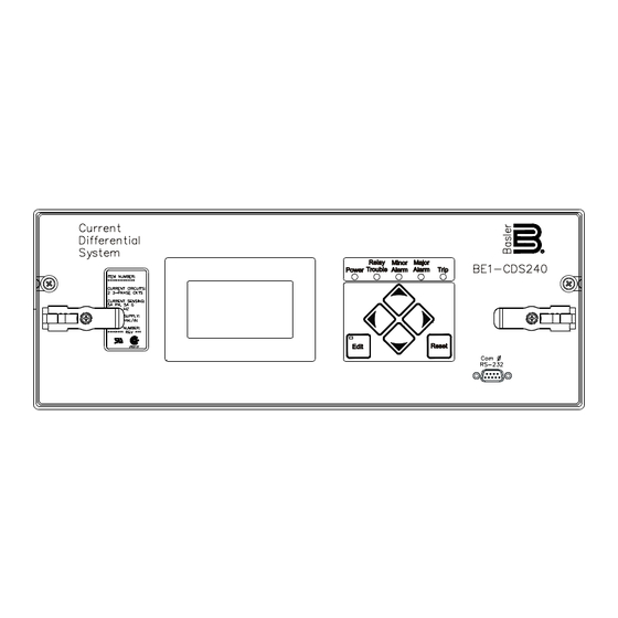
Human-Machine Interface Each BE1-CDS240 comes with a front panel display with LED (light emitting diode) indicators for power, relay trouble alarm, minor alarm, major alarm, and trip. Each BE1-CDS240 also comes with the software application program BESTCOMS for the CDS240. This program is a user ... -
Page 17: Installation
Installation The BE1-CDS240 is available in two, fully draw-out, case styles; MX vertical can be mounted as an M1, M2, FT31, or an FT32. MX horizontal units can be panel mounted or 19" rack mounted. ... -
Page 18: Differential Protection Application Considerations
In addition, digital technology provides a transient monitor function that enables the BE1-CDS240 relay to detect the onset of CT saturation to ride through the condition to further enhance security from misoperation caused by poorly performing CTs. -
Page 19: Problem 2: Measured Current Magnitude Mismatch
This is illustrated in Figure 1-3. BE1-CDS240 Solution The BE1-CDS240 relay applies a tap adjustment factor to the measured currents to cancel the effect of dissimilar CT ratio and voltage bases by converting the currents to per unit quantities on a common base. -
Page 20: Problem 4: Phase Angle Shift
It can be seen that the primary currents flowing into the zone of protection when tap is adjusted for magnitude mismatch still do not sum to zero as shown in Figure 1-4, Illustrations B and C. 1-10 BE1-CDS240 General Information 9365200990 Rev F... - Page 21 180 out of phase with each other. They will always sum to zero (after tap adjust for magnitude mismatch) under all conditions of balance or unbalance except when there is a fault inside the zone of protection. 9365200990 Rev F BE1-CDS240 General Information 1-11...
- Page 22 CT performance calculation. The BE1-CDS240 relays support the traditional solution so that they may be used in retrofit/modernization projects. However, in a numerical relay, it is possible to connect all of the CTs in wye as shown in Figure 1-6 so that the drawbacks mentioned above are not a consideration.
-
Page 23: Figure 1-6. Three-Phase Connections, Delta-Wye Configuration, Internal Phase Compensation
NOTE The BE1-CDS240 relay uses transformer internal connection information to determine the correct phase compensation to use. It is not possible to reliably determine the phase compensation settings based simply upon phase angle shift information because the phase shift from high to low side is dependent upon the phase-sequence of the power system phasors. -
Page 24: Figure 1-7. Traditional Zero-Sequence Trap For Application With Ground Banks
CT delta just as they circulate in the delta of the power transformer on the delta side. The BE1-CDS240 selects the proper phase shift compensation settings to not only provide the correct phase shift but also to block zero-sequence currents as appropriate. -
Page 25: Problem 6: Transformer Energization Inrush And Overexcitation
This application is greatly simplified with the BE1-CDS240. The user can connect all CTs in wye and specify that the delta transformer winding has a ground source. The BE1-CDS240 will apply delta compensation to the wye winding to obtain phase shift and zero-sequence compensation for that current input. -
Page 26: Model And Style Number Description
Finally, the can compensate to maintain accuracy at off-nominal frequency. The BE1-CDS240 uses frequency tracking to adjust the sampling interval to maintain full accuracy across a wide frequency range so that it is both secure and dependable in all applications. For example, tripping of important transformers during a disturbance that causes the system to go unstable can have a catastrophic affect on an already over stressed power system. -
Page 27: Figure 1-8. Style Number Identification Chart
10 to 75 hertz Accuracy: ±0.01 hertz, ±1 least significant digit at 25C Sensing Input 3 Wire Sensing: Phase A - B 4 Wire Sensing: Phase A - Neutral Minimum Frequency Tracking Voltage: 10 V rms 9365200990 Rev F BE1-CDS240 General Information 1-17... -
Page 28: Calculated Values And Accuracy
8 to 24 hours depending on conditions Backup Battery (optional): Greater than 5 years Battery Type: Lithium, 3.6 Vdc, 0.95 Ah (Basler Electric P/N: 9318700012 or Applied Power P/N: BM551902) 87 Differential Functions Restrained Differential (87RPU, 87RT) Pickup Accuracy 5 Ampere CT: ±4% or ±75 mA, whichever is greater... -
Page 29: Figure 1-9. Typical 87 Response Characteristic Curves
Increment: 3.50 3.00 2.50 Unrestrained 2.00 Restrained 1.50 1.00 0.50 0.00 0.0 1.0 2.0 3.0 4.0 5.0 6.0 7.0 8.0 9.0 10. Multiple of Pickup Figure 1-9. Typical 87 Response Characteristic Curves 9365200990 Rev F BE1-CDS240 General Information 1-19... -
Page 30: Nd Neutral Differential Function
0.1 s from 1.0 to 9.99 s 1 s from 10 to 60 s Timing Accuracy #50TP, #50TN: ±0.5% or ±¼ cycle, whichever is greater, plus trip time for instantaneous response (0.0 setting) 1-20 BE1-CDS240 General Information 9365200990 Rev F... -
Page 31: Time Overcurrent Functions
Volts/Hz (24) Pickup Range: 0.5 to 6 V/Hz Accuracy: ±2% Integrating Time Delay Time Dial: 0.0 to 9.9 V/Hz Reset Dial: 0.0 to 9.9 V/Hz Accuracy: 5% or 4 cycles, whichever is greater 9365200990 Rev F BE1-CDS240 General Information 1-21... -
Page 32: Equation 1-1. Time To Trip
0.050 to 600 s Increment: 1 ms from 0 to 999 ms 0.1 s from 1.0 to 9.9 s 1 s from 10 to 600 s Accuracy: ±0.5% or ±1 cycle, whichever is greater 1-22 BE1-CDS240 General Information 9365200990 Rev F... -
Page 33: Phase Overvoltage Function (59P/159P)
±2% or 0.05 A 1 A CT: 0.05 to 2 A Accuracy: ±2% or 0.01 A SEF: 0.01 A to 0.050 A Accuracy: ±2.5% or 0.0025 A Delay Timer: 50 to 999 ms 9365200990 Rev F BE1-CDS240 General Information 1-23... -
Page 34: General Purpose Timers (62, 162, 262, 362)
½ For other current levels, use the formula I = (K/t) where t = time in seconds and K = 160,000. Begins to Clip (saturate): 150 A Burden: <10 m at 5 Aac 1-24 BE1-CDS240 General Information 9365200990 Rev F... -
Page 35: Analog To Digital Converter
Voltage ranges depend on Jumper configuration. See Section 3, Input and Output Functions, Contact Sensing Inputs. Input Burden: Burden per contact for sensing depends on the power supply model and the input voltage. Table 1-1 provides appropriate burden specifications. 9365200990 Rev F BE1-CDS240 General Information 1-25... -
Page 36: Surge Withstand Capability
2,000 Vac at 50/60 Hz in accordance with IEEE C37.90 and IEC 255-5. (Includes communication ports.) Surge Withstand Capability Oscillatory Qualified to IEEE C37.90.1-2001, Standard Surge Withstand Capability (SWC) Tests for Protective Relays and Relay Systems. 1-26 BE1-CDS240 General Information 9365200990 Rev F... -
Page 37: Radio Frequency Interference (Rfi)
12 lb (5.4 kg) maximum Shipping Weight: Approximately 16.5 lb (7.5 kg) Case Configurations M Horizontal: Panel or 19" rack-mount, draw-out M Vertical: M1, M2/FT31, FT32 size, draw-out L Vertical: L2/FT42 size, draw-out 9365200990 Rev F BE1-CDS240 General Information 1-27... - Page 38 This page intentionally left blank. 1-28 BE1-CDS240 General Information 9365200990 Rev F...
-
Page 39: Section 2 Quick Start
Element Logic Settings ........................2-3 Output Logic Settings........................2-3 USER INTERFACES..........................2-3 Front Panel HMI..........................2-3 ASCII Command Communications ....................2-4 BESTCOMS for BE1-CDS240, Graphical User Interface..............2-5 GETTING STARTED..........................2-6 Connections ............................2-6 Entering Test Settings........................2-6 Checking the State of Inputs......................2-7 Testing .............................. - Page 40 This page intentionally left blank. BE1-CDS240 Quick Start 9365200990 Rev F...
-
Page 41: Section 2 Quick Start
This section provides an overview of the BE1-CDS240 Current Differential System. You should be familiar with the concepts behind the user interfaces and BESTlogic before you begin reading about the detailed BE1-CDS240 functions. Sections 3 through 6 in this manual describe in detail each function of the BE1- CDS240. -
Page 42: Characteristics Of Protection And Control Elements
In the 16 character preprogrammed logic name, the last 4 characters refer to revision A, dash (-), and BE (Basler Electric). When customizing a programmed logic scheme, it is recommended that the user include the revision level of their scheme and change the BE to a 2-digit code representative of the user's company name. -
Page 43: Element Logic Settings
LCD. A complete description of the HMI is included in Section 10, Human- Machine Interface. The BE1-CDS240 HMI is menu driven and organized into a menu tree structure with six branches. A complete menu tree description with displays is also provided in Section 10, Human-Machine Interface. A list of the menu branches and a brief description for scrolling through the menu is in the following paragraphs. -
Page 44: Ascii Command Communications
Figure 2-2. 51 HMI Screen ASCII Command Communications The BE1-CDS240 relay has three independent communications ports for serial communications. Basler Terminal in BESTCOMS can be connected to any of the three ports so that the user may send commands to the relay. Alternatively, a computer terminal or PC running a terminal emulation program ... -
Page 45: Bestcoms For Be1-Cds240, Graphical User Interface
See Section 11, ASCII Command Interface, for a more detailed discussion of how to use ASCII text files for setting the relay. BESTCOMS for BE1-CDS240, Graphical User Interface Basler Electric's graphical user interface (GUI) software, BESTCOMS, is an alternative method for quickly developing setting files in a friendly, Windows based environment. -
Page 46: Getting Started
The GUI also allows for downloading industry standard COMTRADE files for analysis of stored oscillography data. Detailed analysis of the oscillography files may be accomplished using Basler Electric's BESTWAVE software. For more information on Basler Electric's Windows based BESTCOMS (GUI) software, refer to Section 14, BESTCOMS Software. -
Page 47: Checking The State Of Inputs
From this position, press the Right scrolling pushbutton until you have reached the screen titled, \STATUS BE1-CDS240 REPORT STATUS. From this position, press the Down scrolling pushbutton one time (\STAT\TARGETS) and press the Right scrolling pushbutton three times. At this time, you should see the OPERATIONAL STATUS Screen, \STAT\OPER_STAT. - Page 48 What voltage level is used to develop current flow through the contact sensing inputs? Voltage level is dependent on the power supply option (BE1-CDS240 style) and the position of the contact-sensing jumper. See Section 12, Installation, for additional information. How can the BE1-CDS240 be configured into a simple transformer differential relay? Two preprogrammed schemes perform this function.
- Page 49 HMI and front RS-232 are considered the same port. Access needs to be gained only when a write to the BE1-CDS240 is required (control or setting change or report reset). Data can be read and reports can be obtained without gaining access. After gaining access though one of the ports, the session can be ended with the Exit command.
- Page 50 18.) Can the IRIG signal be daisy-chained to multiple BE1-CDS240 units? Yes, multiple BE1-CDS240 units can use the same IRIG input signal by daisy-chaining the BE1-CDS240 inputs. The burden data is non-linear, approximately 4 kilo-ohms at 3.5 Vdc and 3 kilo-ohms at 20 Vdc.
-
Page 51: Section 3 Input And Output Functions
Figure 3-8. Inputs and Outputs Screen, Inputs 1-6 Tab ................3-16 Figure 3-9. Output Logic, General Purpose Output Contacts ..............3-18 Figure 3-10. Output Logic, Fail-Safe Alarm Output Contact ..............3-18 Figure 3-11. Inputs and Outputs Screen, Outputs 1-14, A Tab............... 3-19 9365200990 Rev F BE1-CDS240 Input and Output Functions... - Page 52 Table 3-6. Internal Compensation Chart ....................3-14 Table 3-7. Contact Sensing Turn-On Voltage ..................3-15 Table 3-8. Digital Input Conditioning Function Settings ................3-17 Table 3-9. Output Hold Function Settings ....................3-19 BE1-CDS240 Input and Output Functions 9365200990 Rev F...
-
Page 53: Section 3 • Input And Output Functions
CT ratio.) The virtual circuits are user configurable to sum either two or three of the analog inputs. For each virtual circuit, the BE1-CDS240 calculates the summation and provides a sum for A, B, C phase currents, negative-sequence current, and neutral current. The virtual currents can be used throughout the... -
Page 54: Voltage Measurement
A-phase current circuit one. When the applied signal is greater than 10 volts, or 0.5 amps (0.1 amps for 1 A CTs) the BE1-CDS240 measures the frequency. The measured frequency on the voltage input is used by the 81 function and applies to all measurements and calculations; the current input is used in the sampling rate determination. -
Page 55: Power Measurement
Equation 3-9 WATTs Equation 3-10 VARs where based sensing type For AB, BC, or CA VT connection with ACB phase-sequence: Equation 3-11 WATTs 9365200990 Rev F BE1-CDS240 Input and Output Functions... -
Page 56: Measurement Functions Setup
Virtual Circuit Setup 0 - 13 GND is valid for CT 4 input only when configuring the BE1-CDS240 for a 2 independent ground input. Power System / VT Setup To enter Power System or VT settings, select General Operation from the Screens pull-down menu. Then select the Power System / VT Setup tab. - Page 57 Dependency of other relay system elements on 1 pu Inom is far less critical and using the CT secondary rating will have little functional impact. VTP Setup, VT Ratio. The BE1-CDS240 requires setting information about the VT ratio, the VT connections, the operating modes for the 27/59 and 51/27R functions, the current circuit that is used to compute power, and power flow polarity.
-
Page 58: Ct Setup
CT ratio. The BE1-CDS240 automatically takes this factor into account so it is not necessary for the user to manually compensate when entering the CT ratio. -
Page 59: Transformer Setup
SG-CKT command. For each circuit, you can set Connection, Insert Zero Sequence Trap, Differential Circuit, and Circuit Polarity. You can also set Transformer Phase Relationships, Individual circuits to be used for restraint, and Virtual Circuits. 9365200990 Rev F BE1-CDS240 Input and Output Functions... - Page 60 CT configurations. Mathematically, the compensation factors provide the following: Note: A 1/(square root of 3) factor is missing from the compensation equations. See Table 3-6 for the net compensation equations. BE1-CDS240 Input and Output Functions 9365200990 Rev F...
- Page 61 CT configurations. The BE1-CDS240 can also compensate for phase “mismatch”. That is, if A phase of the incoming system is connected to the transformer primary H1 and A phase of the secondary system is connected to X2, the phases can be matched at the relay with this feature.
- Page 62 Table 3-3. CT Input Circuit Settings 1 for Delta/Wye Circuit Applications BE1-CDS240 Settings Compensation Applied Transformer CT Input Connection Connection Phase Rotation NONE DAB for DAB connections DAC for DAC connections NONE NONE NONE NONE NONE 3-10 BE1-CDS240 Input and Output Functions 9365200990 Rev F...
- Page 63 Table 3-4. CT Input Circuit Settings 2 for Delta/Wye Circuit Applications BE1-CDS240 Settings Compensation Applied Transformer CT Input Connection Connection Phase Rotation NONE NONE NONE NONE 9365200990 Rev F BE1-CDS240 Input and Output Functions 3-11...
- Page 64 Table 3-5. CT Input Circuit Settings 3 for Delta/Wye Circuit Applications BE1-CDS240 Settings Compensation Applied Transformer CT Input Connection Connection Phase Rotation DDAB NONE NONE NONE NONE 3-12 BE1-CDS240 Input and Output Functions 9365200990 Rev F...
- Page 65 Screens 5.1.1.3, 5.2.1.3, 5.3.1.3 and 5.4.1.3, \PROT\SG#\87\TAP in order to enter the new CT settings. See Section 4, Protection and Control, Phase Differential Protection, for more information on the auto-tap calculation function. 9365200990 Rev F BE1-CDS240 Input and Output Functions 3-13...
-
Page 66: Iec Transformer Setup
D-Y-Z + clock method. For instance, a transformer connection will be Dy1 rather than a DAB/Y, though some dual designations will be used for 3-14 BE1-CDS240 Input and Output Functions 9365200990 Rev F... -
Page 67: Contact Sensing Inputs
Vdc nominal sensing voltages. See Table 3-7 for the control voltage ranges. Each BE1-CDS240 is delivered with the contact-sensing jumpers installed for operation in the high end of the control voltage range in “H” or high position. If the contact sensing inputs are to be operated at the lower end of the control voltage range, the jumpers must be changed to the “L”... -
Page 68: Digital Input Conditioning Function
Time. The labels include a label to describe the input, a label to describe the Energized State, and a label to describe the De-Energized State. Labels are used by the BE1-CDS240’s reporting functions. To edit the settings or labels, select Inputs and Outputs from the Screens pull-down menu. Then select the Inputs 1-6 or Inputs 7-12 tab. -
Page 69: Retrieving Input Status Information From The Relay
OUTPUTS BE1-CDS240 relays have ten or fourteen general-purpose output contacts (OUT1 through OUT14) and one fail-safe, normally closed (relay in de-energized state), alarm output contact (OUTA). Each output is isolated and rated for tripping duty. All relays outputs are high speed (one-quarter cycle nominal operating time). -
Page 70: Retrieving Output Status
How to do this is described in Section 7, BESTlogic Programmable Logic, Application Tips. The hold timer can be enabled for each input from the ASCII command input using the SG-HOLD command. Hold timer settings are shown in Table 3-9. 3-18 BE1-CDS240 Input and Output Functions 9365200990 Rev F... -
Page 71: Output Logic Override Control
Pulsing an Output Contact Outputs can be pulsed to provide the push-to-energize function provided in Basler Electric solid-state relays. This is useful in trip testing the protection and control system. When pulsed, the contact changes... -
Page 72: Holding An Output Contact Open Or Closed
OUT=P EXECUTED 3. Disable the trip output (OUT1) by holding it at logic 0. >CS-OUT1=0 OUT1=0 SELECTED >CO-OUT1=0 OUT1=0 EXECUTED 4. Return OUT1 to logic control. >CS-OUT1=L OUT1=L SELECTED >CO-OUT1=0 OUT1=L EXECUTED 3-20 BE1-CDS240 Input and Output Functions 9365200990 Rev F... -
Page 73: Retrieving Output Logic Override Status
(0) or closed (1) state. A P indicates that the contact is being pulsed and will return to logic control automatically. 9365200990 Rev F BE1-CDS240 Input and Output Functions 3-21... - Page 74 This page intentionally left blank. 3-22 BE1-CDS240 Input and Output Functions 9365200990 Rev F...
-
Page 75: Section 4 Protection And Control
BESTlogic Settings for Auxiliary Overvoltage................4-46 Operating Settings for Auxiliary Overvoltage................4-47 Retrieving Auxiliary Overvoltage Status from the Relay............... 4-48 47 - Negative-Sequence Overvoltage Protection................4-48 BESTlogic Settings for Negative-Sequence Overvoltage ............4-49 9365200990 Rev F BE1-CDS240 Protection and Control... - Page 76 Figure 4-19. Percentage Differential Screen, 87ND/187ND Tab ............4-23 Figure 4-20. Instantaneous Overcurrent Logic Block ................4-23 Figure 4-21. BESTlogic Function Element Screen, Phase (50TP) ............4-24 Figure 4-22. Overcurrent Screen, 50T/150T Tab ..................4-26 BE1-CDS240 Protection and Control 9365200990 Rev F...
- Page 77 Table 4-10. BESTlogic Settings for Instantaneous Overcurrent ............. 4-25 Table 4-11. Operating Settings for Instantaneous Overcurrent .............. 4-26 Table 4-12. BESTlogic Settings for Time Overcurrent ................4-28 Table 4-13. Operating Settings for Time Overcurrent ................4-30 9365200990 Rev F BE1-CDS240 Protection and Control...
- Page 78 Equation 4-11. Time OC Characteristics for Trip ..................4-32 Equation 4-12. Time OC Characteristics for Reset ................. 4-32 Equation 4-13. Time to Trip ........................4-37 Equation 4-14. Time to Reset........................4-37 Equation 4-15. Time to Reset........................4-41 BE1-CDS240 Protection and Control 9365200990 Rev F...
-
Page 79: Section 4 Protection And Control
SECTION 4 PROTECTION AND CONTROL GENERAL BE1-CDS240 relays provide many functions that can be used for protection and control of power system equipment in and around the protected zone. Four settings groups are provided for adapting the coordination under various operating conditions with options for controlling which settings are active by automatic or programmable logic criteria. -
Page 80: Bestlogic Settings For Setting Group Control
Setting Group Selection from the Screens pull-down menu. Then select the BESTlogic button in the lower left hand corner of the screen. Alternately, settings may be made using the SL-GROUP ASCII command. Figure 4-2. BESTlogic Function Element Screen, Setting Group Selection BE1-CDS240 Protection and Control 9365200990 Rev F... - Page 81 Figure 4-3 shows an example of how the inputs are read when the setting group control function logic is enabled for Mode 1. Note that a pulse on the D3 input while D0 is also active doesn’t cause a setting group change to SG3 because the AUTO input is active. 9365200990 Rev F BE1-CDS240 Protection and Control...
- Page 82 AUTO input. Note that a pulse on the D1 input while D0 is also active doesn't cause a setting change to SG3 because the AUTO input is active. D2647-21 08-21-98 AUTO Figure 4-4. Input Control Mode 2 BE1-CDS240 Protection and Control 9365200990 Rev F...
-
Page 83: Operating Settings For Setting Group Control
Settings. The Settings menu is used to select the setting group that the elements settings apply to. Using the pull-down menus and buttons, make the application appropriate settings to the Setting Group Selection function. Table 4-3 summarizes the operating settings for Setting Group Control. 9365200990 Rev F BE1-CDS240 Protection and Control... - Page 84 Current varies but stays below 75 percent for 5 minutes and at time = 75, Setting Group 2 becomes active and the setting change output pulses. After 20 minutes, Setting Group 0 becomes active and the setting change output pulses. BE1-CDS240 Protection and Control 9365200990 Rev F...
- Page 85 If the return time delay setting is set to 0 for a setting group, automatic return for that group is disabled and the relay will remain in that setting group until returned manually of by logic override control. 9365200990 Rev F BE1-CDS240 Protection and Control...
-
Page 86: Logic Override Of The Setting Group Control Function
<mode> entry of CS-GROUP command and CO-GROUP command must match or setting group selection will be rejected. If more than 30 seconds elapse after issuing a CS-GROUP command, the CO-GROUP command will be rejected. BE1-CDS240 Protection and Control 9365200990 Rev F... -
Page 87: Retrieving Setting Group Control Status From The Relay
DIFFERENTIAL PROTECTION 87 - Phase Differential Protection BE1-CDS240 relays provide three-phase percentage restrained differential protection with high-speed unrestrained instantaneous differential protection. The differential protection includes harmonic restraint to improve security in transformer applications. The 87 function (see Figure 4-8) has nine outputs 87RPU (restrained pickup), 87RT (restrained trip), 87UT (unrestrained trip), 2NDHAR (second harmonic A, B, C restraint picked up), and 5THHAR (fifth harmonic A, B, C restraint picked up). - Page 88 Inhibit Unrestrained 5th Harmonic setting Status Harmonic Restraint Current Transient Fund I Monitor 87 Unrestrained Trip Unrestrained 2X Unrestrained Element setting D2840-24.vsd 02-08-99 Figure 4-9. 87 Phase Differential Protection Functional Block Diagram 4-10 BE1-CDS240 Protection and Control 9365200990 Rev F...
- Page 89 In many cases, the second harmonic content of the inrush current may show up primarily in only one or two phases, which can cause one or two phases to not be inhibited. The BE1-CDS240 relay allows the second harmonic currents to be shared between the three phases. When second harmonic sharing is...
-
Page 90: Bestlogic Settings For Phase Differential
Table 4-4 summarizes the BESTlogic settings for Phase Differential. Table 4-4. BESTlogic Settings for Phase Differential Function Range/Purpose Default 0 = disabled Mode 1 = enabled Logic expression that disables function when TRUE. 4-12 BE1-CDS240 Protection and Control 9365200990 Rev F... -
Page 91: Tap Compensation Settings For Phase Differential
The input currents can be tap adjusted up to a spread ratio of 10:1. If the ratio between TAP1, and TAP2, 3, or 4 is greater than ten, it will be necessary to adjust the CT ratios to bring the tap factors closer 9365200990 Rev F BE1-CDS240 Protection and Control 4-13... - Page 92 Three-phase versions of the BE1-87T also allow internal phase compensation. The jumper settings for the BE1-87T correspond to the internal compensation for the BE1-CDS240 as follows: 1 = DAC and 2 = DAB. When calculating the tap adjust settings for the BE1-87T, the 3 COMPn factor has to be included regardless of whether phase compensation is done by connecting the CTs in delta or by using internal delta compensation.
-
Page 93: Operating Settings For Phase Differential
Times Tap. The definitions for the remaining variables in Equation 4-3 are the same as those for Equation 4-1. TAPn 1000 COMPn TAPn CTRn Ipri TAPn TAPn CTRn COMPn Equation 4-2. Tab Adjustment Equation Equation 4-3. Calculate Primary Amps 9365200990 Rev F BE1-CDS240 Protection and Control 4-15... -
Page 94: Retrieving Phase Differential Status From The Relay
To avoid this condition, the BE1-CDS240 provides a Virtual Restraint Element that derives its restraint from the vector sum of two or more high or low side breaker CT inputs (see Section 3, Input and Output Functions, for details on the virtual circuit measurement function and settings). - Page 95 The latter however, could make 87R prone to false operation when full load or external fault current flows through the transformer. Virtual restraint provides a practical way to solve this problem without adding an additional CT. 9365200990 Rev F BE1-CDS240 Protection and Control 4-17...
-
Page 96: 87Nd - Neutral Differential Protection
Using the same example as above, first configure Virtual Circuit 5 for the vector sum of CT Circuits 1 and 2. Next, enable virtual restraint to use Virtual Circuit 5 as one of its restraining inputs. When virtual restraint is enabled to use Virtual Circuit 5, the BE1-CDS240 automatically excludes Circuits 1 and 2 from the restraint calculations. - Page 97 The Operating Current function determines the magnitude of the differential current as the phasor sum of the compensated currents. 9365200990 Rev F BE1-CDS240 Protection and Control 4-19...
-
Page 98: Bestlogic Settings For Neutral Differential
Then select the 87ND/187ND tab. Select the appropriate BESTlogic button for 87ND or 187ND. Alternately, these settings can be made using the SL-87ND and SL-187ND ASCII commands. Figure 4-18. BESTlogic Function Element Screen, Neutral (87ND) 4-20 BE1-CDS240 Protection and Control 9365200990 Rev F... -
Page 99: Auto-Tap Compensation Settings For Neutral Differential
Differential from the Screens pull-down menu. Then select the 87ND/187ND tab. Alternately, settings may be made using S<g>-87ND and S<g>-187ND ASCII commands or through the optional HMI Screens 5.#.2.1, \PROT\SG#\87ND\87ND, 5.#.2.2, \PROT\SG#\187ND\187ND. The operating settings for Neutral Differential are provided in Table 4-9. 9365200990 Rev F BE1-CDS240 Protection and Control 4-21... - Page 100 The 87ND neutral differential operational settings may be entered with BESTCOMS (Figure 4-19), or from the optional front panel HMI from Screens 5.#.2.1, \PROT\SG#\87ND7\87ND, or from the ASCII command interface using the S<g>-87ND command. 4-22 BE1-CDS240 Protection and Control 9365200990 Rev F...
-
Page 101: Retrieving Neutral Differential Status From The Relay
See Section 3, Inputs and Outputs, for details on the virtual current circuits. The instantaneous overcurrent protective functions in the BE1-CDS240 relay are labeled 50T because each has a settable time delay. If the time delay is set to zero, they operate as instantaneous overcurrent relays. -
Page 102: Bestlogic Settings For Instantaneous Overcurrent
Then, select the BESTlogic variable, or series of variables to be connected to the input. Select Save when finished to return to the BESTlogic Function Element screen. For more details on the 4-24 BE1-CDS240 Protection and Control 9365200990 Rev F... -
Page 103: Operating Settings For Instantaneous Overcurrent
50T elements. To open the screen, select Overcurrent from the Screens pull-down menu. Then select the 50T/150T, 250T/350T, etc. tab. Alternately, settings may be made using S<g>-x50T ASCII command or through the optional HMI Screens 5.#.3.1 - 5.#.3.4, \PROT\SG#\x50T\. 9365200990 Rev F BE1-CDS240 Protection and Control 4-25... - Page 104 0.01 cycles from the ASCII command interface. Time delays entered in cycles are converted to milliseconds or seconds. Increment precision after conversion is limited to that appropriate for each of those units of measure. 4-26 BE1-CDS240 Protection and Control 9365200990 Rev F...
-
Page 105: Retrieving Instantaneous Overcurrent Status From The Relay
TRUE and the fault recording function trip logic expression is TRUE. See Section 6, Reporting and Alarm Functions, Fault Reporting, for more details on the target reporting function. 9365200990 Rev F BE1-CDS240 Protection and Control 4-27... -
Page 106: Bestlogic Settings For Time Overcurrent
Circuit 3, 4 = CT Input Circuit 4, 5 = CT Input Circuit 5, 6 = CT Input Circuit. Mode G = Independent Ground Input (#51N functions only) Logic expression that disables function when TRUE. 4-28 BE1-CDS240 Protection and Control 9365200990 Rev F... -
Page 107: Operating Settings For Time Overcurrent
Beside the Logic pull-down menu is a pull-down menu labeled Settings. The Settings menu is used to select the setting group that the element's settings apply to. Table 4-13 summarizes the operating settings for Time Overcurrent. 9365200990 Rev F BE1-CDS240 Protection and Control 4-29... -
Page 108: Retrieving Time Overcurrent Status From The Relay
When set for Control mode of operation, the phase overcurrent element is disabled until the measured voltage drops below the threshold. Thus, as long as the voltage on the appropriate phase is above the 4-30 BE1-CDS240 Protection and Control 9365200990 Rev F... - Page 109 100%. NOTE For single-phase sensing, the unmonitored phase is not restrained or controlled. These phases are marked in the table by N/A (not applicable). 9365200990 Rev F BE1-CDS240 Protection and Control 4-31...
-
Page 110: Operating Settings For Voltage Restraint/Control For Time Overcurrent
Affects the effective range of the time dial. to selected curve Coefficient specific Affects a constant term in the timing equation. Has greatest effect to selected curve on curve shape at high multiples of tap. 4-32 BE1-CDS240 Protection and Control 9365200990 Rev F... -
Page 111: Setting Programmable Curves
46 curve by the process described in Appendix A, Time Overcurrent Characteristic Curves. The K factor is the time the generator can withstand 1 per unit I where 1 pu is the relay setting for nominal current. 9365200990 Rev F BE1-CDS240 Protection and Control 4-33... -
Page 112: Negative-Sequence Overcurrent Protection
When these two factors (3/2 and 1/3) are combined, the 3 factors cancel which leaves the one-half factor. Figure 4-28. Phase-to-Phase Fault Magnitude Figure 4-29. Sequence Components for an A-B Fault 4-34 BE1-CDS240 Protection and Control 9365200990 Rev F... -
Page 113: Coordination Settings For Negative-Sequence Overcurrent
1/3 per unit of the magnitude of the phase-to-ground fault for which you wish to have backup protection. VOLTAGE PROTECTION BE1-CDS240 voltage protection includes elements for overexcitation, phase undervoltage, phase overvoltage, negative-sequence overvoltage, and over/underfrequency. 24 - Volts per Hertz Overexcitation Protection Overexcitation occurs when a generator or transformer magnetic core becomes saturated. -
Page 114: Theory Of Operation For Volts Per Hertz Overexcitation
The maximum time delay is determined by Equation 4-13 with (V/Hz measured / V/Hz nominal) set equal to 1.001. The overall inverse time delay range is limited to 1,000 seconds maximum and 0.2 seconds minimum. 4-36 BE1-CDS240 Protection and Control 9365200990 Rev F... -
Page 115: Bestlogic Settings For Volts Per Hertz Overexcitation
To open the BESTlogic Function Element screen for Overexcitation (24), select Voltage Protection from the Screens pull-down menu and select the 24 tab. Then, select the BESTlogic button. Alternately, settings may be made using SL-24 ASCII command. Figure 4-31. BESTlogic Function Element Screen, 24 9365200990 Rev F BE1-CDS240 Protection and Control 4-37... -
Page 116: Operating Settings For Volts Per Hertz Overexcitation
Protection from the Screens pull-down menu and select the 24 Tab. Alternately, settings can be made using the S<g>-24 and S<g>-24D commands or at the optional front panel HMI using Screen 5.#.5.1, \PROT\SG#\24\24. Figure 4-32. Voltage Protection Screen, 24 Tab 4-38 BE1-CDS240 Protection and Control 9365200990 Rev F... -
Page 117: Programmable Alarm For Volts Per Hertz Overexcitation
Figures 4-33 and 4-34 show examples of a transformer and generator limit curve along with the optimum composite protection characteristic. NOTE Actual damage curves must be obtained from the equipment manufacturer for particular equipment to be protected. 9365200990 Rev F BE1-CDS240 Protection and Control 4-39... - Page 118 Assuming a Vnom of 69.3 volts phase-neutral, 1 pu volts/hertz = (69.3 * 3) / 60 = 2.00. Using IEEE/C37.102, "Guide for AC Generator Protection" as a guide for setting overexcitation protection, the following example demonstrates how to set the BE1-CDS240 to provide a composite V/Hz characteristic for protection of a generator and a step-up transformer: •...
- Page 119 30% instead of 0%, therefore tripping in 70% or the original trip time or 35 seconds. Figure 4-36 illustrates the inverse time delay and reset time. Figure 4-36. Inverse Time Delay and Reset Time 9365200990 Rev F BE1-CDS240 Protection and Control 4-41...
-
Page 120: Retrieving Volts Per Hertz Overexcitation Status From The Relay
At the top center of the BESTlogic Function Element screen is a pull-down menu labeled Logic. This menu allows viewing of the BESTlogic settings for each preprogrammed logic scheme. A custom logic 4-42 BE1-CDS240 Protection and Control 9365200990 Rev F... - Page 121 Undervoltage or overvoltage on all three phases causes pickup. Logic expression that disables function when TRUE. Example 1. Make the following BESTlogic settings to the 27P element. Refer to Figure 4-38. Mode: At least 1of 3 phases BLK: 9365200990 Rev F BE1-CDS240 Protection and Control 4-43...
-
Page 122: Operating Settings For Phase Undervoltage/Overvoltage
Time setting that represents the element's time delay defaults to milliseconds. It is also selectable for seconds, minutes, and cycles. Operating settings for Phase Undervoltage/Overvoltage are summarized in Table 4-23. 4-44 BE1-CDS240 Protection and Control 9365200990 Rev F... -
Page 123: Retrieving Phase Undervoltage/Overvoltage Status From The Relay
When this expression is TRUE, the element is disabled by forcing the outputs to logic 0 and resetting the timer. This feature functions in a similar way to the torque control contact of an electromechanical relay. 9365200990 Rev F BE1-CDS240 Protection and Control 4-45... -
Page 124: Bestlogic Settings For Auxiliary Overvoltage
Save when finished to return to the BESTlogic Function Element screen. For more details on the BESTlogic Expression Builder, see Section 7, BESTlogic Programmable Logic. Select Done when the settings have been completely edited. 4-46 BE1-CDS240 Protection and Control 9365200990 Rev F... -
Page 125: Operating Settings For Auxiliary Overvoltage
Beside the Logic pull-down menu is a pull-down menu labeled Settings. The settings menu is used to select the setting group that the elements settings apply to. Figure 4-42. Voltage Protection Screen, 59X Tab 9365200990 Rev F BE1-CDS240 Protection and Control 4-47... -
Page 126: Retrieving Auxiliary Overvoltage Status From The Relay
The 47 element is enabled or disabled by the Mode input. Two modes are available. Selecting Mode 0 disables protection. Mode 1 enables the 47 element. More information about logic mode selections is provided in the BESTlogic Settings for Negative-Sequence Overvoltage paragraphs. 4-48 BE1-CDS240 Protection and Control 9365200990 Rev F... -
Page 127: Bestlogic Settings For Negative-Sequence Overvoltage
Select Save when finished to return to the BESTlogic Function Element screen. For more details on the BESTlogic Expression Builder, see Section 7, BESTlogic Programmable Logic. Select Done when the settings have been completely edited. 9365200990 Rev F BE1-CDS240 Protection and Control 4-49... -
Page 128: Operating Settings For Negative-Sequence Overvoltage
(Per U Volts), and percent volts (% Volts) can also be selected as the pickup setting unit of measure. The unit of measure for the Time setting that represents the element's time delay defaults to milliseconds. It is also selectable for seconds, minutes, and cycles. 4-50 BE1-CDS240 Protection and Control 9365200990 Rev F... -
Page 129: Retrieving Negative-Sequence Overvoltage Status From The Relay
Power system frequency is measured on the optional auxiliary voltage input as well. When the applied voltage is greater than 10 volts, the BE1-CDS240 measures the frequency. Frequency element designations are 81, 181, 281, 381, 481, and 581. Each of the six elements has identical inputs, outputs, and setting provisions. -
Page 130: Bestlogic Settings For Over/Underfrequency
BESTlogic settings for each preprogrammed logic scheme. A custom logic scheme must be created and selected in the Logic pull-down menu at the top of the screen before BESTlogic settings can be changed. See Section 7, BESTlogic Programmable Logic. Enable the 4-52 BE1-CDS240 Protection and Control 9365200990 Rev F... -
Page 131: Operating Settings For Over/Underfrequency
INH/81/181/281/381/481/581 tab. Alternately, settings may be made using the S<g>- <x>81 ASCII command or the optional HMI interface using Screens 5.#.10.1 and 5.#.10.2, \PROT\SG#\81\SETTINGS. Figure 4-48. Voltage Protection Screen, INH/81/181/281/381/481/581 Tab 9365200990 Rev F BE1-CDS240 Protection and Control 4-53... -
Page 132: Retrieving Over/Underfrequency Status From The Relay
The status of each logic variable can be determined through the ASCII command interface using the RG- STAT (report general-status) command. See Section 6, Reporting and Alarm Functions, General Status Reporting, for more information. The status can also be determined using BESTCOMS Metering screen. 4-54 BE1-CDS240 Protection and Control 9365200990 Rev F... -
Page 133: Breaker Failure Protection
BREAKER FAILURE PROTECTION 50BF - Breaker Failure Protection BE1-CDS240 relays provide four independent breaker failure protection functions. Each current circuit has an associated breaker failure function. For example, Current Circuit 1 is internally connected to 50BF; Current Circuit 2 is internally connected to 150 BF and so on. This section discuses 50BF but applies to all BF functions. -
Page 134: Bestlogic Settings For Breaker Failure
Save when finished to return to the BESTlogic Function Element Screen. For more details on the BESTlogic Expression Builder, see Section 7, BESTlogic Programmable Logic. Select Done when the settings have been completely edited. Table 4-30 summarizes the BESTlogic settings for Breaker Failure. 4-56 BE1-CDS240 Protection and Control 9365200990 Rev F... -
Page 135: Operating Settings For Breaker Failure
The default unit of measure for the Pickup setting is secondary amps. The unit of measure for the Time setting that represents the element's time delay defaults to milliseconds. It is also selectable for seconds, minutes, and cycles. Table 4-31 summarizes the operating settings for Breaker Failure. 9365200990 Rev F BE1-CDS240 Protection and Control 4-57... -
Page 136: Retrieving Breaker Failure Status From The Relay
LOGIC TIMERS 62 - General Purpose Logic Timers BE1-CDS240 relays provide four gene ral-purpose logic timers, which are extremely versatile. Each can be set for one of five modes of operation to emulate virtually any type of timer. Each function block has one output (62, 162, 262, or 362) that is asserted when the timing criteria has been met according to the BESTlogic mode setting. -
Page 137: Mode 1, Pu/Do (Pickup/Dropout Timer)
FALSE for the duration of DROPOUT time delay setting T2. If the INITIATE input expression toggles to TRUE before time T2, the output stays TRUE and the T2 timer is reset. D2843-08 10-23-03 Figure 4-53. Mode 1, PU/DO (Pickup/Dropout Timer) 9365200990 Rev F BE1-CDS240 Protection and Control 4-59... -
Page 138: Mode 2, One-Shot Nonretriggerable Timer
ON time of T1 and an OFF time of T2. When the BLOCK input is held TRUE, the oscillator stops and the output is held OFF. Figure 4-56. Mode 4, Oscillator 4-60 BE1-CDS240 Protection and Control 9365200990 Rev F... -
Page 139: Mode 5, Integrating Timer
TRUE. The timer will time for DELAY time T1 and then the output will latch TRUE. Additional INITIATE input expression changes of state are ignored. Time (T2) is ignored. Refer to Figure 4-58. D2863-07 10-23-03 Figure 4-58. Mode 6, Latch 9365200990 Rev F BE1-CDS240 Protection and Control 4-61... -
Page 140: Bestlogic Settings For General Purpose Logic Timers
Logic Mode 5 = Integrating 2 = One Shot Non-Retrig 6 = Latch 3 = One Shot Retrig INITIATE Logic expression that initiates timing sequence. BLOCK Logic expression that disables function when TRUE. 4-62 BE1-CDS240 Protection and Control 9365200990 Rev F... -
Page 141: Operating Settings For General Purpose Logic Timers
0.1 for 0.1 to 9.9 sec. T1 Time, 0.1 to 9999 sec. Seconds 1.0 for 10 to 9999 sec. T2 Time 0 to 599,940 (60 Hz) Cycles 0 to 499,950 (50Hz) 9365200990 Rev F BE1-CDS240 Protection and Control 4-63... -
Page 142: Retrieving General Purpose Logic Timers Status From The Relay
60FL - Fuse Loss Detection BE1-CDS240 relays have one 60FL element that can be used to detect fuse loss or loss of potential in a three-phase system. The 60FL element is illustrated in Figure 4-61. When the element logic becomes TRUE, the 60FL logic output becomes TRUE. -
Page 143: Fuse Loss Detection Blocking Settings
60FL element. Select Reporting and Alarms from the Screens pull-down menu and select the VT Monitor tab. Alternately, settings may be made using the SP-60FL ASCII command. See Section 11, ASCII Command Interface, Command Summary, Protection Setting Commands, for more information. 9365200990 Rev F BE1-CDS240 Protection and Control 4-65... - Page 144 Similarly, zero-sequence voltage polarization can only be performed if 3P4W sensing is selected. The following qualifiers are applied to the voltage polarized ground direction element based on the user selected input quantity: 4-66 BE1-CDS240 Protection and Control 9365200990 Rev F...
-
Page 145: Retrieving Fuse Loss Detection Status From The Relay
Reporting, for more information. The status can also be determined using BESTCOMS Metering screen. VIRTUAL SWITCHES 43 - Virtual Selector Switches The BE1-CDS240 Current Differe ntial System has eight virtual selector switches that can provide manual control, locally and remotely, without using physical switches and/or interposing relays. Each virtual switch can be set for one of three modes of operation to emulate virtually any type of binary (two position) switch. -
Page 146: Bestlogic Settings For Virtual Selector Switches
Default 0 = Disabled 2 = On/Off Mode 1 = On/Off/Pulse 3 = Off/Momentary On Example 1. Make the following BESTlogic settings to the Virtual Switch function. See Figure 4-65. Mode: On/Off 4-68 BE1-CDS240 Protection and Control 9365200990 Rev F... -
Page 147: Select Before Operate Control Of Virtual Selector Switches
An example of an operate command not matching the select command. >CO-243=1 ERROR:NO SELECT (Note: Must ent er “CS-243=1” first to select.) Figure 4-66. Virtual Switches Screen, 43 – 143 – 243 – 343 Tab 9365200990 Rev F BE1-CDS240 Protection and Control 4-69... -
Page 148: Retrieving Virtual Selector Switches Status From The Relay
A virtual switch can be used instead of a physical switch to reduce costs with the added benefit that the virtual switch can be operated both locally from the HMI and remotely from a substation computer or modem connection to an operator's console. The BE1-CDS240 relays provide four Virtual Breaker Control Switches (101, 1101, 2101, and 3101). -
Page 149: Select Before Operate Control Of Virtual Breaker Control Switches
CO-x101 control command will be accepted. The control selected and the operation sele cted must match exactly or the operate command will be blocke d. If the operate command is blocke d and error message is output. 9365200990 Rev F BE1-CDS240 Protection and Control 4-71... -
Page 150: Retrieving Virtual Breaker Control Switch Status From The Relay
HMI Screens 2.2.1 through 2.2.4 provide switch control and displays the status of the virtual control switches (after-trip or after-close). As the previous Example 1 demonstrated, the state of each virtual selector switch can be determined using the CO-2101 command in a read-only mode. 4-72 BE1-CDS240 Protection and Control 9365200990 Rev F... -
Page 151: Section 5 Metering
Figure 5-3. Metering - Alarms, Targets, Output Status, Input Status ............5-3 Figure 5-4. Metering - Logic Bits Views..................... 5-3 Tables Table 5-1. Auto Ranging Scales for Metered Values ................5-1 Table 5-2. ASCII Command and HMI Metering Cross-Reference ............5-4 9365200990 Rev F BE1-CDS240 Metering... - Page 152 This page intentionally left blank. BE1-CDS240 Metering 9365200990 Rev F...
-
Page 153: Section 5 Metering
Section 3, Input and Output Functions, Power System Inputs, Power Measurement. Energy measurement is covered in Section 6, Reporting and Alarm Functions. Auto Ranging The BE1-CDS240 automatically scales metered values. Table 5-1 illustrates the ranges for each value metered. Table 5-1. Auto Ranging Scales for Metered Values... - Page 154 Figure 5-1. Metering - Circuits 1 - 6 Other metering views can be selected from the View pull-down menu. These alternate views are shown in Figures 5-2 through 5-4. Figure 5-2. Metering - Watts/Vars/VA, Phase-Phase, Sequence, Phase-Neutral, Ground 1, Frequency BE1-CDS240 Metering 9365200990 Rev F...
- Page 155 Figure 5-3. Metering - Alarms, Targets, Output Status, Input Status Figure 5-4. Metering - Logic Bits Views 9365200990 Rev F BE1-CDS240 Metering...
- Page 156 M5-IA, M6-IA M1-IB, M2-IB, Current, Circuits 1-6, B-phase M3-IB, M4-IB, \METER\CRNT\CT_1-6\I_MEAS M5-IB, M6-IB M1-IC, M2-IC, Current, Circuits 1-6, C-phase M3-IC, M4-IC, \METER\CRNT\CT_1-6\I_MEAS M5-IC, M6-IC M1-IN, M2-IN, Current, Circuits 1-6, Neutral M3-IN, M4-IN, \METER\CRNT\CT_1-6\I_CALC M5-IN, M6-IN BE1-CDS240 Metering 9365200990 Rev F...
- Page 157 \METER\DIFF\COMP\IN Voltage The BE1-CDS240 meters A-phase voltage, B-phase voltage, C-phase voltage, voltage across phases A and B, phases B and C, and phases A and C. Positive-sequence voltage, negative-sequence voltage, and three-phase zero-sequence (residual) voltage are also metered. The VTP connection determines what is measured.
-
Page 158: Current
+1,500 kilovars. True Power True power is metered over a range of –7,500 kilowatts to +7,500 kilowatts on five-ampere nominal systems. One-ampere nominal systems meter true power over a range of –1,500 watts to +1,500 watts. BE1-CDS240 Metering 9365200990 Rev F... -
Page 159: Section 6 Reporting And Alarm Functions
Figure 6-2. Reporting and Alarms Screen, Clock Display Mode Tab............6-2 Figure 6-3. Reporting and Alarms Screen, I Demand Tab ................ 6-8 Figure 6-4. Reporting and Alarms Screen, V & P Demand Tab.............. 6-10 Figure 6-5. Differential Alarm Characteristics..................6-14 9365200990 Rev F BE1-CDS240 Reporting and Alarm Functions... - Page 160 Table 6-19. Oscillographic Records Settings ..................6-35 Table 6-20. Relay Trouble Alarms......................6-39 Table 6-21. Programmable Alarms......................6-39 Table 6-22. Programmable Alarm Settings ..................... 6-42 Equations Equation 6-1. Energy Data Equation ......................6-7 BE1-CDS240 Reporting and Alarm Functions 9365200990 Rev F...
-
Page 161: Introduction
It is important to attach (label) meaningful names to the relays and the relay reports. To provide this feature, BE1-CDS240 relays have four relay identification fields: Relay ID, Station ID, User Label 1, and User Label 2. These fields are used in the header information lines of the Fault Reports, the Oscillographic Records, and the Sequence of Events Recorder (SER) Reports. -
Page 162: Clock
CLOCK The BE1-CDS240 provides a real-time clock with capacitor backup that is capable of operating the clock for up to eight hours after power is removed from the relay. The clock is used by the demand reporting function, the fault reporting function, the oscillograph recording function, and the sequence of events recorder function to time-stamp events. -
Page 163: Alternate Dst (Daylight Saving Time) Settings
SG-UTC=M,R,B M (Offset from UTC in Minutes) = -720 to 840 R (Reference Time) = 0 (Local) or 1 (UTC) B (Bias: amount of minutes to adjust DST) = 0 to 300 9365200990 Rev F BE1-CDS240 Reporting and Alarm Functions... -
Page 164: General Status Reporting
Refer to Section 11, ASCII Command Interface, for a list of all ASCII commands. GENERAL STATUS REPORTING BE1-CDS240 relays have extensive capabilities for reporting relay status. This is important for determining the health and status of the system for diagnostics and troubleshooting. Throughout this manual, reference is made to the RG-STAT (report general, status) report and the appropriate HMI screens for determining the status of various functions. -
Page 165: Other Report General Commands
If the command RG is entered by itself, the relay reports the time, date, target information, and other reports as shown in the following example. The RG-VER command has multiple line outputs and is not read with the RG command. 9365200990 Rev F BE1-CDS240 Reporting and Alarm Functions... - Page 166 Table 6-3. Logic Variable Status Report Format BE1-CDS240 Reporting and Alarm Functions 9365200990 Rev F...
-
Page 167: Energy Data
In addition, the demand reporting function keeps an additional set of registers for Yesterday's Peak. Each day at midnight, the demand reporting function 9365200990 Rev F BE1-CDS240 Reporting and Alarm Functions... -
Page 168: Setting The Demand Reporting Function
Demand Circuits pull-down menu. Using the pull-down menus and buttons, make the application appropriate current demand settings. Demand reporting settings are summarized in Table 6-4. Figure 6-3. Reporting and Alarms Screen, I Demand Tab BE1-CDS240 Reporting and Alarm Functions 9365200990 Rev F... -
Page 169: Retrieving Demand Reporting Information
DWATT ASCII command or with BESTCOMS (Figure 6-4). The SA-DVAR ASCII command is used to set the Var Positive and Negative demand thresholds, which can also be set using BESTCOMS (Figure 6-4). Alternately, HMI Screen \SETUP\DMD\ALARMS, can be used to set all demand alarms. 9365200990 Rev F BE1-CDS240 Reporting and Alarm Functions... -
Page 170: Optional Load Profile Recording Function
Optional Load Profile Recording Function Load profile recording is an optional selection when the BE1-CDS240 is ordered. The Load Profile, 4000 Point Data Array option (2 or 3 as the third character from the right in the style chart) uses a 4,000-point data array for data storage. -
Page 171: Differential Current Monitoring Function
Primary current (MEASURED I PRI) is calculated simply as the secondary current multiplied by the CT turns ratio. Secondary current (MEASURED I SEC) is the current actually measured by the relay. Angle compensated current (ANGLE COMPENSATED I) is the 9365200990 Rev F BE1-CDS240 Reporting and Alarm Functions 6-11... - Page 172 200.8 @ 180 200.8 @ 60 200.8 @ 300 CT CKT3 125.5 @ 151 125.5 @ 31 125.5 @ 271 CT CKT4 54.5 @ 180 54.5 @ 60 54.4 @ 300 6-12 BE1-CDS240 Reporting and Alarm Functions 9365200990 Rev F...
-
Page 173: Setting Differential Current Monitoring Alarms
Function Range Increment Unit of Measure Default Differential Alarm Level 50 – 100 Percent (%) Retrieving Differential Current Monitoring Information To retrieve the differential check record, use the ASCII command RA-DIFF. 9365200990 Rev F BE1-CDS240 Reporting and Alarm Functions 6-13... - Page 174 D2850-15 05-27-99 RESTRAINT CURRENT (IN MULTIPLES OF TAP) Figure 6-5. Differential Alarm Characteristics Figure 6-6. Percentage Differential Screen, Diff Alarm Tab 6-14 BE1-CDS240 Reporting and Alarm Functions 9365200990 Rev F...
-
Page 175: Transformer Monitoring Functions
Screen 6.6.1, \SETUP\XFRMR\DUTY. This function selects the transformer CT to be monitored that also affects the transformer alarm function (SA-TX). Table 6-8 lists the settings for the transformer duty monitoring function. 9365200990 Rev F BE1-CDS240 Reporting and Alarm Functions 6-15... -
Page 176: Transformer Alarms
(through-fault counter or through-fault duty). That is, you may program an alarm threshold (limit) to monitor each function. Alternately, you may program three different alarm thresholds to monitor one of the monitored functions. The transformer alarms may be programmed using BESTCOMS 6-16 BE1-CDS240 Reporting and Alarm Functions 9365200990 Rev F... -
Page 177: Vt Monitor Functions
To open the screen shown in Figure 6-8, select Reporting and Alarms, from the Screens pull-down menu. Then select the VT Monitor tab. Alternately, settings may be made using the SP-60FL ASCII command. 9365200990 Rev F BE1-CDS240 Reporting and Alarm Functions 6-17... -
Page 178: Breaker Monitoring
Figure 6-8. Reporting and Alarms Screen, VT Monitor Tab BREAKER MONITORING Depending on the system scheme, one BE1-CDS240 relay can provide overcurrent protection for more than one circuit breaker. However, breaker-monitoring functions provide extensive monitoring and alarms for only a single circuit breaker. This extensive monitoring helps to manage equipment inspection and maintenance expenses. -
Page 179: Breaker Duty Monitoring
When the breaker opens, the N power of the current interrupted in each pole of the circuit breaker is accumulated by the breaker duty monitor. Breaker opening is defined by the breaker status monitoring 9365200990 Rev F BE1-CDS240 Reporting and Alarm Functions 6-19... - Page 180 OR logic term (e.g., IN1 or VO7) which blocks the breaker monitoring logic when TRUE (1). BLKBKR is set to zero to disable blocking. When breaker monitoring is blocked (logic expression equals 1), breaker duty is not accumulated. 6-20 BE1-CDS240 Reporting and Alarm Functions 9365200990 Rev F...
- Page 181 Breaker interruption duty T ransformer (W hen SG-TRIGGER (PU) is TRUE) fault duty Setting group (W hen SG-TRIGGER (PU) is TRUE) D2843-42 change blocked 09-29-03 Figure 6-10. Protective Fault Analysis 9365200990 Rev F BE1-CDS240 Reporting and Alarm Functions 6-21...
- Page 182 Breaker Duty Monitoring function for Circuits 1 - 4. To open the screen, select Reporting and Alarms from the Screens pull-down menu. Then select the Bkr Duty tab. Alternately, settings may be made using the SB-DUTY ASCII command. 6-22 BE1-CDS240 Reporting and Alarm Functions 9365200990 Rev F...
- Page 183 BESTlogic Expression Builder, See Section 7, BESTlogic Programmable Logic. Select Done when the settings have been completely edited. Figure 6-12. BESTlogic Function Element Screen, Circuit 1 Breaker Duty Monitoring, Block 9365200990 Rev F BE1-CDS240 Reporting and Alarm Functions 6-23...
-
Page 184: Breaker Alarms
BESTCOMS. Figure 6-13 illustrates the BESTCOMS screen used to select settings for the Breaker Alarms function. Alternately, settings may be made using the SA-BKR ASCII command or the HMI using Screen 6.5.2, \SETUP\BKR\ALARM. 6-24 BE1-CDS240 Reporting and Alarm Functions 9365200990 Rev F... -
Page 185: Trip Circuit Monitor
If this current flow presents a problem for the application, the monitor circuits can be physically disconnected by Connectors P5, P6, P7, and P8. Figure 6-14 shows the trip Figure 6-14. Trip Circuit Monitor Logic circuit monitor logic. 9365200990 Rev F BE1-CDS240 Reporting and Alarm Functions 6-25... - Page 186 This may cause false tripping of the other devices and prevent the BE1-CDS240 trip circuit monitor from reliably detecting an open circuit. If this situation exists, the trip coil monitor can be removed from the circuit.
-
Page 187: Fault Reporting
Fault Reporting Expressions and Settings The fault reporting function records and reports information about faults that have been detected by the relay. The BE1-CDS240 provides many fault reporting features. These features include Fault Summary Reports, Sequence of Events Recorder Reports, Oscillographic Records, and Targets. -
Page 188: Targets
TRUE (refer to Figure 6-11 and Table 6-10, call-out B). Target information can be viewed and reset at the HMI and through the communication ports. 6-28 BE1-CDS240 Reporting and Alarm Functions 9365200990 Rev F... - Page 189 Alternately, targets can be enabled using the SG-TARG ASCII command. Using the SG-TARG command, you can select which protective elements trigger a target and what type of logic condition will reset the targets. 9365200990 Rev F BE1-CDS240 Reporting and Alarm Functions 6-29...
- Page 190 Figure 6-19. Target Reset Logic target reports are still available from the HMI menu branch 4, Reports. Password access is not required to reset targets at the HMI. Figure 6-19 illustrates the target reset logic. 6-30 BE1-CDS240 Reporting and Alarm Functions 9365200990 Rev F...
-
Page 191: Fault Summary Reports
Reports must be gained to reset the targets using the ASCII command interface. Fault Summary Reports The BE1-CDS240 records information about faults and creates fault summary reports. A maximum of 16 fault summary reports are stored in the relay. The two most recent reports are stored in nonvolatile memory. - Page 192 The following example illustrates a typical fault summary report. Call-outs shown in the report are references to the gend of Table 6-11. 6-32 BE1-CDS240 Reporting and Alarm Functions 9365200990 Rev F...
- Page 193 Breaker Failure: A fault was detected as defined by the pickup expression and the breaker failure trip became TRUE before the fault was cleared. RF=TRIG: A fault report was recorded by the ASCII command interface. 9365200990 Rev F BE1-CDS240 Reporting and Alarm Functions 6-33...
- Page 194 RF-NEW. If additional detail is desired, Sequence of Events Recorder data and Oscillographic data can be obtained for the faults also. This is discussed in greater detail later in this section. 6-34 BE1-CDS240 Reporting and Alarm Functions 9365200990 Rev F...
-
Page 195: Oscillographic Records
OSC (settings general, oscillography) ASCII command. See Table 6- 19 for possible settings. Table 6-19. Oscillographic Records Settings Range 6, 8, 10, 12, 15, 16, 20, 24, 32 Default Figure 6-22. Oscillographic Records 9365200990 Rev F BE1-CDS240 Reporting and Alarm Functions 6-35... - Page 196 Software for IBM compatible computers is available from Basler Electric to convert binary files to ASCII format. The download protocol may be either XMODEM or XMODEM CRC format. For ease of reference the name of the downloaded file should be the same as the command.
-
Page 197: Sequence Of Events Recorder
SER Directory Report A directory report lists the number of events currently in memory and the time span that the events cover. Directory reports are accessed using the RS (report SER) command. 9365200990 Rev F BE1-CDS240 Reporting and Alarm Functions 6-37... -
Page 198: Alarms Function
If your application requires a normally closed contact that opens to indicate a relay trouble condition, use BESTlogic to program the output logic. One of the output relays with normally open contacts (OUT1 6-38 BE1-CDS240 Reporting and Alarm Functions 9365200990 Rev F... -
Page 199: Major, Minor, And Logic Programmable Alarms
Trip circuit continuity and voltage monitor 3 (OUT9). CKT MON 4 OPEN ALARM Trip circuit continuity and voltage monitor 4 (OUT10). BKR 1 FAIL ALARM Breaker Failure Initiate > Control Time (50BF). 9365200990 Rev F BE1-CDS240 Reporting and Alarm Functions 6-39... - Page 200 LOGIC = NONE ALARM Active Logic=NONE. No logic selected. PHASE DEMAND 1 ALARM Circuit 1 Phase Current Demand threshold exceeded. PHASE DEMAND 2 ALARM Circuit 2 Phase Current Demand threshold exceeded. 6-40 BE1-CDS240 Reporting and Alarm Functions 9365200990 Rev F...
- Page 201 Alternately, settings for Major, Minor, and Logic alarms can be made using the SA-MAJ, SA-MIN, or SA- LGC ASCII commands. Refer to Section 11, ASCII Command Interface, Command Summary, Alarm Setting Commands, for complete command descriptions. 9365200990 Rev F BE1-CDS240 Reporting and Alarm Functions 6-41...
- Page 202 DIAG/ALARM line of the General Status Report. Refer to the General Status Reporting subsection for more information about obtaining relay status with the RG-STAT command. Figure 6-27 shows the alarm reset logic. 6-42 BE1-CDS240 Reporting and Alarm Functions 9365200990 Rev F...
-
Page 203: Links Between Programmable Alarms And Bestlogic
Pressing the front panel Reset key when HMI Screen 1.2, \STAT\ALARMS is active. By connecting the alarms reset logic in BESTCOMS. Alternately, this can be done using the SA- RESET ASCII command. 9365200990 Rev F BE1-CDS240 Reporting and Alarm Functions 6-43... -
Page 204: Hardware And Software Version Reporting
To view the version of the relay once the download is complete, select General Operation from the Screens pull-down menu. Then select the Identification tab (Figure 6-30). The General Info tab (Figure 6- 31) displays all of the style information about the relay. 6-44 BE1-CDS240 Reporting and Alarm Functions 9365200990 Rev F... - Page 205 Figure 6-30. General Operation Screen, Identification Tab Figure 6-31. General Operation Screen, General Info Tab 9365200990 Rev F BE1-CDS240 Reporting and Alarm Functions 6-45...
-
Page 206: Settings Compare
If there are any differences in the two files, a dialog box will pop up notifying you that Differences Are Found. The BESTCOMS Settings Compare dialog box pops up (Figure 6-33) where you can select to Show All or Show Diffs. Figure 6-33. BESTCOMS Settings Compare Dialog Box 6-46 BE1-CDS240 Reporting and Alarm Functions 9365200990 Rev F... -
Page 207: Section 7 Bestlogic Programmable Logic
Figure 7-7. BESTlogic Expression Builder Screen.................. 7-10 Figure 7-8. BESTlogic Screen, Logic Select Tab ..................7-11 Tables Table 7-1. Logic Variable Names and Descriptions .................. 7-7 Table 7-2. Programmable Variable Name Setting................... 7-13 9365200990 Rev F BE1-CDS240 BESTlogic Programmable Logic... - Page 208 This page intentionally left blank. BE1-CDS240 BESTlogic Programmable Logic 9365200990 Rev F...
-
Page 209: Introduction
LOGIC INTRODUCTION Multifunction relays such as the BE1-CDS240 Current Differential System are similar in nature to a panel of single-function protective relays. Both must be wired together with ancillary devices to operate as a complete protection and control system. In the single-function static and electromechanical environment, elementary diagrams and wiring diagrams provide direction for wiring protective elements, switches, meters, and indicator lights into a unique protection and control system. - Page 210 Figure 7-1. BESTlogic Function Blocks - page 1 of 5 BE1-CDS240 BESTlogic Programmable Logic 9365200990 Rev F...
- Page 211 Figure 7-2. BESTlogic Function Blocks - page 2 of 5 9365200990 Rev F BE1-CDS240 BESTlogic Programmable Logic...
- Page 212 Figure 7-3. BESTlogic Function Blocks - page 3 of 5 BE1-CDS240 BESTlogic Programmable Logic 9365200990 Rev F...
- Page 213 Figure 7-4. BESTlogic Function Blocks - page 4 of 5 9365200990 Rev F BE1-CDS240 BESTlogic Programmable Logic...
- Page 214 Figure 7-5. BESTlogic Function Blocks - page 5 of 5 BE1-CDS240 BESTlogic Programmable Logic 9365200990 Rev F...
- Page 215 150BF Tripped 451NT 451 Neutral Tripped BFRT2 150BF Retrip 451NPU 451 Neutral Picked Up BFT3 250BF Tripped BFRT3 250BF Retrip BFT4 350BF Tripped BFRT4 350BF Retrip Fuse Loss 60FL 60 Loss of Potential Alarm 9365200990 Rev F BE1-CDS240 BESTlogic Programmable Logic...
- Page 216 181 Tripped 181PU 181 Picked Up 281T 281 Tripped 281PU 281 Picked Up 381T 381 Tripped 381PU 381 Picked Up 481T 481 Tripped 481PU 481 Picked Up 581T 581 Tripped 581PU 581 Picked Up BE1-CDS240 BESTlogic Programmable Logic 9365200990 Rev F...
-
Page 217: Function Block Logic Settings
A virtual output exists only as a logical state inside the relay (VO1 through VO15). A hardware output is a physical relay contact that can be used for protection or control. The BE1-CDS240 relay has up to 14 isolated output contacts (I/O Option E) (OUT1 - OUT14) consisting of two Form C output contacts (OUT1,2) and 12 Form A output contacts (OUT 3-14). -
Page 218: Logic Schemes
Unneeded inputs or outputs may be left open to disable a function. Or a function element can be disabled through operating settings. Unused current sensing inputs should be shorted to minimize noise pickup. 7-10 BE1-CDS240 BESTlogic Programmable Logic 9365200990 Rev F... -
Page 219: The Active Logic Scheme
Naming the new logic distinguishes it from the preprogrammed logic scheme. In the 16 character preprogrammed logic name, the last 4 characters refer to revision A, dash (-), and BE (Basler Electric). When customizing a programmed logic scheme, it is recommended that the user include the revision level of their scheme and change the BE to a 2-digit code representative of the user's company name. -
Page 220: Custom Logic Schemes
If there are problems with a customized logic scheme, the RG-STAT command can be used to check the status of all logic variables. More information about the RG-STAT command can be found in Section 6, Reporting and Alarm Functions. 7-12 BE1-CDS240 BESTlogic Programmable Logic 9365200990 Rev F... -
Page 221: User Input And Output Logic Variable Names
Input and output logic variable names are assigned by typing them into the appropriate text box on the related BESTCOMS screen. All of the BE1-CDS240’s inputs, outputs, and 43 switches have labels that can be edited. Table 7-2 shows the range and purpose of each label. Alternately, labels may be edited using the SN-ASCII command. - Page 222 This page intentionally left blank. 7-14 BE1-CDS240 BESTlogic Programmable Logic 9365200990 Rev F...
-
Page 223: Section 8 Application
Block Neutral and Negative Sequence Protection ................8-54 Setting Group Selection ........................8-54 Output Contact Seal-in ........................8-55 Latching a Tripping Contact ......................8-56 Latching a Programmable Logic Alarm or Creating a Pseudo Target ..........8-57 9365200990 Rev F BE1-CDS240 Application... - Page 224 Figure 8-6. Typical Logic Diagram for CDS240-TXCL-B-BE..............8-19 Figure 8-7. Typical Logic Diagram for CDS240-TXBU-B-BE ..............8-25 Figure 8-8. Device Interconnection for Integrated Protection System using BE1-CDS240 for Transformer Protection and BE1-851 or BE1-951 for Bus and Feeder Protection........8-26 Figure 8-9.
- Page 225 Table 8-37. Miscellaneous Logic Expressions ..................8-52 Table 8-38. Output Contact Seal-in Logic ....................8-56 Table 8-39. Logic Settings Associated with Figure 8-19 ................. 8-58 9365200990 Rev F BE1-CDS240 Application...
- Page 226 This page intentionally left blank. BE1-CDS240 Application 9365200990 Rev F...
-
Page 227: Section 8 Application
Transformer with Control Logic, Basic Transformer with Backup Logic, Bus Protection with Backup Logic, and Motor Protection are available on the Basler Web site and included in the logic library of BESTCOMS, Basler Electric's Windows based graphical user interface program. A description of each of those schemes follows the Basic Transformer discussion. -
Page 228: Overview Of Preprogrammed Basic Transformer Protection Logic
Basler Electric products are among the most reliable in the industry, but we believe that it does not make good engineering sense to place all your eggs in one basket. That is why Basler strongly recommends that a second multifunction device be installed to provide independent backup and zone overlapping for each protected zone. -
Page 229: Cds240-Batx-A-Be Logic Scheme (Basic Transformer Protection)
SL-251Q=2,0 SL-VO14=IN7 SL-351P=0,0 SL-VO15=IN8 SL-351N=0,0 SL-OUTA=VOA SL-351Q=0,0 SL-OUT1=VO1 SL-451N=0,0 SL-OUT2=VO1 SL-24=0,0 SL-OUT3=VO1 SL-27P=0,0 SL-OUT4=VO4 SL-127P=0,0 SL-OUT5=VO5 SL-47=0,0 SL-OUT6=VO6 SL-59P=0,0 SL-OUT7=0 SL-59X=0,0 SL-OUT8=0 SL-159P=0,0 SL-OUT9=0 SL-81=0,0 SL-OUT10=0 SL-181=0,0 SL-OUT11=0 SL-281=0,0 SL-OUT12=0 SL-381=0,0 SL-OUT13=0 SL-481=0,0 SL-OUT14=0 SL-581=0,0 9365200990 Rev F BE1-CDS240 Application... - Page 230 Out4 52-1 151P 151N 151Q Out2 Out1 CT Input 1 Out3 CT Input G (Optional) CT Input 2 Out5 251P 251N 251Q 52-2 CT Input 2 D2843-33 02-26-03 Figure 8-1. Typical One-line Diagram for CDS240-BATX-A-BE BE1-CDS240 Application 9365200990 Rev F...
- Page 231 (N only) is connected to a ground CT at the grounded side of a delta-wye transformer. The ground-input (G) is an option on the BE1-CDS240 and must be ordered. Paralleled CTs inside a delta tertiary (3Io) can also feed the 51N. The 87, 51, 151, and 251 protection elements are logic enabled by the settings shown in Table 8-1 to provide a trip through the BE1-CDS240 output contacts.
-
Page 232: Integration Of Protection, Control, And I/O Elements
SER reporting. For example, sudden INPUT_6, IN6 - IN8 pressure trip or transformer hot spot alarm, etc. INPUT_7, CLOSED OPEN Drives VO13 - VO15 that are programmable INPUT_8 alarm points 21 - 23. Label inputs as appropriate. BE1-CDS240 Application 9365200990 Rev F... - Page 233 BESTlogic Expression: VO1=87RT+87UT Time overcurrent trip. May be VO4 TRUE if any time 151TRIP- used to direct trip main overcurrent (51N, 151P, N, or TRIP NORMAL breaker or lockout. Q) trip occurs. BESTlogic Expression: VO4=51NT+151NT+151PT+151QT 9365200990 Rev F BE1-CDS240 Application...
- Page 234 BESTlogic Expression: OUT1=VO1 OUT2 contact closes if restrained or unrestrained OUT2 Phase differential trip. trip occurs. BESTlogic Expression: OUT2=VO1 OUT3 contact closes if restrained or unrestrained OUT3 Phase differential trip. trip occurs. BESTlogic Expression: OUT3=VO1 BE1-CDS240 Application 9365200990 Rev F...
-
Page 235: Cds240-Ba87-B-Be (Basic Differential) Logic Scheme
The following preprogrammed logic schemes can be found in logic library of BESTCOMS for the CDS240 or at the Basler Electric Web site. Two of the logic schemes are intended for use on transformers. One of the schemes is for motor protection with a speed sensing input, one is for bus protection with backup, and one is a basic 87 function designed for multiple applications including transformer, motor, bus, or generator protection. -
Page 236: Cds240-Bsbu-A-Be (Bus Protection With Backup) Logic Scheme
BE1-CDS240 are hard wired to the feeder protection package, providing a high-speed backup, bus interlocked, zone of bus protection. When the BE1-CDS240 detects a feeder relay out of service, the BE1-CDS240 50/51P, N, and Q protection elements and outputs are automatically reconfigured to provide feeder protection. -
Page 237: Cds240-Ba87-B-Be (Basic Differential) Logic Scheme
SL-VO15=IN8 SL-251Q=0,0 SL-OUTA=VOA SL-351P=0,0 SL-OUT1=VO1 SL-351N=0,0 SL-OUT2=VO1 SL-351Q=0,0 SL-OUT3=VO1 SL-451N=0,0 SL-OUT4=VO4 SL-24=0,0 SL-OUT5=0 SL-27P=0,0 SL-OUT6=VO6 SL-127P=0,0 SL-OUT7=0 SL-47=0,0 SL-OUT8=0 SL-59P=0,0 SL-OUT9=0 SL-59X=0,0 SL-OUT10=0 SL-159P=0,0 SL-OUT11=0 SL-81=0,0 SL-OUT12=0 SL-181=0,0 SL-OUT13=0 SL-281=0,0 SL-OUT14=0 SL-381=0,0 SL-481=0,0 SL-581=0,0 9365200990 Rev F BE1-CDS240 Application 8-11... - Page 238 Figure 8-3. Typical One-line Diagram for CDS240-BA87-B-BE 8-12 BE1-CDS240 Application 9365200990 Rev F...
-
Page 239: Protection Elements
CT input 1. The 87 and 51 protection elements are logic enabled by the programming shown in Table 8-3 to provide a trip through the BE1-CDS240 output contacts. Typically, the 87 protection element provides high-speed percent restrained, phase and ground protection for faults inside the differential zone. - Page 240 Input 2 Logic: No manual selection logic is used. 1 (Discrete GROUP Inputs) Input 3 Logic: No manual selection logic is used. Auto/Manual Logic: Set to 1 (/0) to enable automatic selection. No manual selection is used. 8-14 BE1-CDS240 Application 9365200990 Rev F...
- Page 241 NORMAL TRUE. 22 is enabled. BESTlogic Expression: VO14=IN7 Optional. Use to annunciate VO15 is TRUE when IN8 is VO15 an alarm when alarm point IN8-ALARM ACTIVE NORMAL TRUE. 23 is enabled. BESTlogic Expression: VO15=IN8 9365200990 Rev F BE1-CDS240 Application 8-15...
-
Page 242: Cds240-Txcl-B-Be (Basic Transformer With Control) Logic Scheme
CDS240-TXCL-B-BE application and how the elements are logically wired together (equations). If the user should decide to build on this scheme, all elements required for a more detailed application are available through programming. For programming details, refer to Section 7, BESTlogic Programmable Logic. 8-16 BE1-CDS240 Application 9365200990 Rev F... - Page 243 SL-351P=0,0 SL-VO14=IN7 SL-351N=0,0 SL-VO15=IN8 SL-351Q=0,0 SL-OUTA=VOA SL-451N=0,0 SL-OUT1=VO1 SL-24=0,0 SL-OUT2=VO2 SL-27P=0,0 SL-OUT3=VO3 SL-127P=0,0 SL-OUT4=VO4 SL-47=0,0 SL-OUT5=VO5 SL-59P=0,0 SL-OUT6=VO6 SL-59X=0,0 SL-OUT7=0 SL-159P=0,0 SL-OUT8=0 SL-81=0,0 SL-OUT9=0 SL-181=0,0 SL-OUT10=0 SL-281=0,0 SL-OUT11=0 SL-381=0,0 SL-OUT12=0 SL-481=0,0 SL-OUT13=0 SL-581=0,0 SL-OUT14=0 9365200990 Rev F BE1-CDS240 Application 8-17...
- Page 244 151Q Out3 Out2 CT Input 1 CT Input G (Optional) CT Input 2 Out4 251P 251N 251Q Out5 Auto/Manual 52-2 Group Control CT Input 2 D2843-35 02-26-03 Figure 8-5. Typical One-line Diagram for CDS240-TXCL-B-BE 8-18 BE1-CDS240 Application 9365200990 Rev F...
-
Page 245: Protection Elements
(N only) is connected to a ground CT at the grounded side of a delta-wye transformer. The ground input (G) is an option on the BE1-CDS240 and must be ordered. Paralleled CTs inside a delta tertiary (3Io) can also feed the 51N. The 87, 51, 151, and 251 protection elements are logic enabled to provide a trip through the BE1-CDS240 outputs. -
Page 246: Integration Of Protection, Control, And I/O Elements
SER reporting. For example, sudden pressure trip or transformer hot spot alarm, etc. INPUT_7, IN7, IN8 CLOSED OPEN Drives VO14 and VO15 that are programmable INPUT_8 alarm points 22 and 23. Label inputs as appropriate. 8-20 BE1-CDS240 Application 9365200990 Rev F... - Page 247 2 (On/Off) 87-CUTOFF DISABLD NORMAL closed. Automatic setting group change logic SETGRP- 2 (On/Off) MANUAL AUTO auto/manual switch. CONTROL Allows breaker to be tripped or closed manually from HMI or ASCII command 1 (enabled) interface. 9365200990 Rev F BE1-CDS240 Application 8-21...
- Page 248 PROT- VO12 Protection Picked Up expression. 51N, 151, or 251 NORMAL PICKED-UP element picks up. BESTlogic Expression: VO12=87RPU+87UT+151PPU+251PPU+51NPU+151NPU+251NPU+151QPU+251QPU (Note: 87UT is included to trigger the fault recorder because there is no unrestrained pickup output.) 8-22 BE1-CDS240 Application 9365200990 Rev F...
- Page 249 (closed) and 86 lockout is not tripped. BESTlogic Expression: OUT5=VO5 OUT6 contact closes when any programmed major alarm OUT6 Used to annunciate an alarm. condition is TRUE. BESTlogic Expression: OUT6=VO6 OUT7 - Spare output contacts. BESTlogic Expression: OUT7-14 =0 9365200990 Rev F BE1-CDS240 Application 8-23...
-
Page 250: Cds240-Txbu-B-Be (Transformer Diff With Backup) Logic Scheme
See the paragraphs on BUS WITH BACKUP SCHEME, in this section for an interconnection of BE1-851 or BE1-951 relays providing feeder protection with BE1-CDS240 relays providing bus protection (CDS240-BSBU-A-BE) and transformer protection (CDS240-TXBU-B-BE). - Page 251 CONTROL Mode2 AUTO Mode2 Note: For clarity, multiple variables going to D2850-02 the same OR Gate are shown by a single 09-28-99 line into the OR Gate. Figure 8-7. Typical Logic Diagram for CDS240-TXBU-B-BE 9365200990 Rev F BE1-CDS240 Application 8-25...
- Page 252 Figure 8-8. Device Interconnection for Integrated Protection System using BE1-CDS240 for Transformer Protection and BE1-851 or BE1-951 for Bus and Feeder Protection 8-26 BE1-CDS240 Application 9365200990 Rev F...
-
Page 253: Protection Elements
(N only) is connected to a ground CT at the grounded side of a delta-wye transformer. The ground-input (G) is an option on the BE1-CDS240 and must be ordered. Paralleled CTs inside a delta tertiary (3Io) can also feed the 51N. The 87, 51, 151, and 251 protection elements are logic enabled to provide a trip by the settings shown in Table 8-19. -
Page 254: Integration Of Protection, Control, And I/O Elements
Typically, the 250T protection element is set to coordinate with a high-speed bus-interlocking scheme (851 or BE1-CDS240) to provide a definite time coordination interval of 18 to 20 cycles for bus fault backup protection. The 250T protection element should have a pickup setting greater than the highest feeder instantaneous element to ensure that it will not pickup before any feeder relay. - Page 255 BE1-851 or BE1-951 using one of the preprogrammed schemes with interlock logic. Breaker Failure Initiate by external relays with EXT-BFI-52B- breaker status supervision. Typically used for NORMAL SUPV differential or sudden pressure tripping. 9365200990 Rev F BE1-CDS240 Application 8-29...
-
Page 256: Test Mode
Input 1 Logic: No manual selection logic is used. 2 (Binary GROUP Inputs) Input 2 Logic: No manual selection logic is used. Input 3 Logic: No manual selection logic is used. Auto/Manual Logic: No automatic selection. 8-30 BE1-CDS240 Application 9365200990 Rev F... - Page 257 VO6 TRUE, Feeder relay is out of FDR-BACKUP- BUS logic that a service as indicated by contact open BACKUP NORMAL MODE feeder relay is out of from the feeder relays. service. BESTlogic Expression: VO6=/IN5 9365200990 Rev F BE1-CDS240 Application 8-31...
- Page 258 BESTlogic Expression: OUT1=VO1 Transformer fault trip (86B for OUT2 contact closes when Trip bus breaker via lockout for bus OUT2 example). faults (250T w/ 18-20 cycles delay). BESTlogic Expression: OUT2=VO2 8-32 BE1-CDS240 Application 9365200990 Rev F...
-
Page 259: Cds240-Bsbu-A-Be (Bus With Backup) Logic Scheme
Service” backup protection. Figure 8-10 shows the interconnection of a BE1-CDS240 (CDS240-TXBU-B- BE) for backup protection, a BE1-851 or BE1-951 for feeder protection, and the BE1-CDS240 for bus protection. When interconnected with feeder relays using preprogrammed feeder logic (FDR-W-IL), the CDS240-BSBU-A-BE scheme provides complete backup, except for reclosing, for the feeder relays if relay failure occurs or when they are out of service for testing or maintenance. - Page 260 SL-351N=0,0 SL-VO13=43 SL-351Q=0,0 SL-VO14=SG1 SL-451N=0,0 SL-VO15=/IN8+743 SL-24=0,0 SL-OUTA=VOA SL-27P=0,0 SL-OUT1=VO1 SL-127P=0,0 SL-OUT2=VO2 SL-47=0,0 SL-OUT3=VO3 SL-59P=0,0 SL-OUT4=VO4 SL-59X=0,0 SL-OUT5=VO5 SL-159P=0,0 SL-OUT6=VO6 SL-81=0,0 SL-OUT7=0 SL-181=0,0 SL-OUT8=0 SL-281=0,0 SL-OUT9=0 SL-381=0,0 SL-OUT10=0 SL-481=0,0 SL-OUT11=0 SL-581=0,0 SL-OUT12=0 SL-OUT13=0 SL-OUT14=0 8-34 BE1-CDS240 Application 9365200990 Rev F...
- Page 261 IN8 BUS-W-BU OPTIONAL INSTANTANEOUS FEEDER BACKUP TEST MODE BLOCK MODE P0004-07 08-14-00 Figure 8-10. Device Interconnection for Integrated Protection System Using BE1-CDS240 for Transformer and Bus Protection and BE1-851 Or BE1-951 for Feeder Protection 9365200990 Rev F BE1-CDS240 Application 8-35...
- Page 262 Figure 8-11. Typical One-line Diagram for CDS240-BSBU-A-BE 8-36 BE1-CDS240 Application 9365200990 Rev F...
- Page 263 Figure 8-12. Typical Logic Diagram for CDS240-BSBU-A-BE 9365200990 Rev F BE1-CDS240 Application 8-37...
-
Page 264: Protection Elements
50T protection element is delayed 2 to 4 cycles to allow time for the feeder protection to detect, pickup, and start timing. If the fault is not on a feeder, the 50T protection element of the BE1-CDS240 bus is not blocked and trips in 2 to 4 cycles through Outputs 1 and 4 as previously discussed. The overlapping 250T protection element from the transformer BE1-CDS240 (not shown in Figure 8-11) does not get blocked when the feeder relays are picked up. -
Page 265: Alarms
1 causing the logic to switch to group 1. When the bus BE1-CDS240 is in setting group 1, it is operating in feeder backup mode. This expression is programmed to Virtual Output 14 that drives alarm bit #22 in the programmable alarm mask. It can be masked to drive an alarm LED and alarm display to indicate when the relay is in feeder backup mode and to trip a feeder breaker instead of the bus breaker. - Page 266 Signal from relay on bus source that is using BACKUP logic that a feeder relay is out of BACKUP- BACKUP NORMAL service. BE1-851, BE1-951, or BE1-CDS240 FDR-RELAY using preprogrammed logic scheme BACKUP. Puts the relay in test mode so that the breaker TEST-MODE-...
- Page 267 Input 0 Logic: Switch to setting group 1 if feeder relay is out of service as indicated by closed contact from relay with BACKUP logic such as BE1-851, BE1-951, or BE1-CDS240. Input 1 Logic: No manual selection logic is used.
- Page 268 50T- bus OC trip in normal Elements have 2-4 cycle delay TRIP NORMAL INTERLKD-OC mode or feeder breaker due to interlock with feeder relay inst. Trip in feeder pickups. backup mode. BESTlogic Expression: VO8=50TPT+50TNT+50TQT 8-42 BE1-CDS240 Application 9365200990 Rev F...
- Page 269 BESTlogic Expression: OUTA=VOA BUS fault trip (86B for OUT1 contact closes if restrained differential trip or for high-speed OUT1 example). bus OC trip (50T) and not in feeder backup mode (VO14). BESTlogic Expression: OUT1=VO1 9365200990 Rev F BE1-CDS240 Application 8-43...
-
Page 270: Cds240-Motr-A-Be Motor Protection Logic
CDS240-MOTR-A-BE application and how the elements are logically wired together (equations). If the user should decide to build on this scheme, all elements required for a more detailed application are available through programming. For programming details, refer to Section 7, BESTlogic Programmable Logic. 8-44 BE1-CDS240 Application 9365200990 Rev F... - Page 271 SL-VO14=250TPT*51PPU SL-351P=0,0 SL-VO15=51QPU SL-351N=0,0 SL-OUTA=VOA SL-351Q=0,0 SL-OUT1=VO1 SL-451N=0,0 SL-OUT2=VO2 SL-24=0,0 SL-OUT3=VO3 SL-27P=0,0 SL-OUT4=VO4 SL-127P=0,0 SL-OUT5=VO5 SL-47=0,0 SL-OUT6=VO6 SL-59P=0,0 SL-OUT7=0 SL-59X=0,0 SL-OUT8=0 SL-159P=0,0 SL-OUT9=0 SL-81=0,0 SL-OUT10=0 SL-181=0,0 SL-OUT11=0 SL-281=0,0 SL-OUT12=0 SL-381=0,0 SL-OUT13=0 SL-481=0,0 SL-OUT14=0 SL-581=0,0 9365200990 Rev F BE1-CDS240 Application 8-45...
- Page 272 Rotor Speed Switch Selector Low/High Inertia Selector 50TP Start Detect High Inertia Start/Running Detect 250TP CT Input 1 DIFF CT Input 2 CT Input 2 D2850-30 02-26-03 Figure 8-13. Typical One-line Diagram for CDS240-MOTR-A-BE 8-46 BE1-CDS240 Application 9365200990 Rev F...
-
Page 273: Protection Elements
Virtual Control Switch 243 is set to high inertia mode. The 151P protection element provides locked rotor protection for high inertia motors. It is blocked when Virtual Control Switch 243 is set to low inertia mode. 9365200990 Rev F BE1-CDS240 Application 8-47... -
Page 274: Integration Of Protection, Control, And I/O Elements
When the breaker is closed, 250TP, start/run current detection and 150TP low inertia locked rotor protection, start timing. If the motor comes up to speed before time out of the 150TP 8-48 BE1-CDS240 Application 9365200990 Rev F... -
Page 275: Emergency Trip
The 151P element provides locked rotor protection for high inertia motors. Blocked when low inertia is selected by Switch 243. If high 151P /VO7+/243 1 (Circuit 1) Inertia is selected, it is unblocked when starting as determined by intermediate logic VO7. 9365200990 Rev F BE1-CDS240 Application 8-49... - Page 276 (51P) is picked up and timing to trip. to trip. BESTlogic Expression: VO4=VO14 Unbalance alarm VO5 TRUE, Unbalance protection UNBALANCE TRIP NORMAL output contact. (51Q) is picked up and timing to trip. BESTlogic Expression: VO5=VO15 8-50 BE1-CDS240 Application 9365200990 Rev F...
- Page 277 This condition will trip the motor if allowed to time out. The VO14 Overload alarm. OVERLOAD ALARM NORMAL alarm point is supervised by the 250TP timing out to prevent a spurious alarm during starting. BESTlogic Expression: VO14=250TPT*51PPU 9365200990 Rev F BE1-CDS240 Application 8-51...
-
Page 278: Miscellaneous Logic Expressions
Section 6, Reporting and Alarm Functions, Breaker Monitoring SG-TARG Section 6, Reporting and Alarm Functions, Fault Reporting SG-TRIGGER Section 6, Reporting and Alarm Functions, Fault Reporting ST-DUTY Section 6, Reporting and Alarm Functions, Transformer Monitoring 8-52 BE1-CDS240 Application 9365200990 Rev F... -
Page 279: Application Tips
1=NORMAL 0=ENABLED BLOCK UPSTREAM INSTANTANEOUS TESTMODE ENABLE VIRTUAL SWITCH 1=ENABLED 0=NORMAL PROTECTION PICKED BREAKER VO12 UP EXPRESSION FAILURE TRIP BFPU BREAKER FAILURE D2857-15 VO10 INITIATE EXPRESSION 10-27-99 Figure 8-15. Trip Circuit Continuity and Voltage Monitor 9365200990 Rev F BE1-CDS240 Application 8-53... -
Page 280: Close-Circuit Monitor
This can lead to a misoperation during periods of load imbalance. The BE1-CDS240 provides a neutral and negative sequence demand function that allows monitoring and alarming to prevent load imbalances. -
Page 281: Output Contact Seal-In
Seal-in Logic Table 8-38 that follows. This table is based on the CDS240-BATX-A-BE preprogrammed logic scheme. 52TC OUTPUT OUT1 OPTO LOGIC TRIPPING LOGIC 52CC OUTPUT OUT2 LOGIC CLOSING LOGIC 52TC 52CC D2590-10 03-23-98 Figure 8-17. Output Seal-in Logic Diagram 9365200990 Rev F BE1-CDS240 Application 8-55... - Page 282 VO7 and VO8. Outputs OUT1, OUT2, and OUT3 will then open and OUT5 will close. BE1- CDS240 MAIN P0004-44 02-26-03 Figure 8-18. Station One-line Drawing 8-56 BE1-CDS240 Application 9365200990 Rev F...
-
Page 283: Latching A Programmable Logic Alarm Or Creating A Pseudo Target
19. The user wants to trip and lockout the high side circuit switcher (CSW) for a Sudden Pressure Relay (63_SPR) trip. The SPR trip is to be supervised and sealed in via the BE1-CDS240 relay. Since this is an external function, it is desired that the relay annunciate that the trip came from the SPR instead of an internal protective element. - Page 284 Table 8-39. Logic Settings Associated with Figure 8-19 SL-87=1,0 SL-51P=1,0; SL-51N=1,0; SL-51Q=1,0 SL-VO1=VO7+VO13 SL-VO2=VO7+VO13 SL-VO3=VO7+VO13 SL-VO4=51PT+51NT+51QT SL-VO5=/VO7+/VO13 SL-VO6=ALMMAJ SL-VO7=87RT+87UT+VO8 SL-VO8=VO7*/TRSTKEY SL-VO9=VO13*/ARSTKEY SL-VO11=51PT+51NT+51QT+87RT+87UT SL-VO12=87UT+51PPU+51NPU+51QPU+87RPU SL-VO13=IN4+VO9 SL-OUT1=VO1 SL-OUT2=VO2 SL-OUT3=VO3 SL-OUT4=VO4 SL-OUT5=VO5 SL-OUT6=VO6 8-58 BE1-CDS240 Application 9365200990 Rev F...
-
Page 285: Section 9 Security
Setting Password Protection ......................9-1 Figures Figure 9-1. General Operation Screen, Global Security Tab ..............9-2 Figure 9-2. General Operation Screen, Global Security Tab with Passwords Shown ......9-2 Tables Table 9-1. Password Protection Settings ....................9-3 9365200990 Rev F BE1-CDS240 Security... - Page 286 This page intentionally left blank. BE1-CDS240 Security 9365200990 Rev F...
- Page 287 Control. Each functional area can be assigned a unique password or one password can be assigned to multiple areas. A global password is used to access all three of the functional areas. BE1-CDS240 passwords are not case sensitive; either lowercase or uppercase letters may be entered. Password security only limits write operations;...
- Page 288 Control Access. See Figure 9-2. Each access level may be enabled (or not enabled) for COM 0 Front RS- 232 and HMI, COM 1 Rear RS-232, and COM 2 Rear RS-485. Access levels may also be enabled for multiple ports. Figure 9-2. General Operation Screen, Global Security Tab with Passwords Shown BE1-CDS240 Security 9365200990 Rev F...
- Page 289 User defined alphanumeric string with a maximum of 8 characters. Password A setting of 0 (zero) disables password protection. 0 = Front RS-232 port Com ports 1 = Rear RS-232 port 2 = Rear RS-485 port 9365200990 Rev F BE1-CDS240 Security...
- Page 290 This page intentionally left blank. BE1-CDS240 Security 9365200990 Rev F...
-
Page 291: Section 10 Human-Machine Interface
Figure 10-5. BE1-CDS240 Menu Tree (Metering PRI/SEC Branch)............10-5 Figure 10-6. BE1-CDS240 Menu Tree (Reports Branch) ............... 10-6 Figure 10-7. BE1-CDS240 Menu Tree (Protection Branch) (1 of 2) ............10-7 Figure 10-8. BE1-CDS240 Menu Tree (Protection Branch) (2 of 2) ............10-8 Figure 10-9. - Page 292 This page intentionally left blank. BE1-CDS240 Human-Machine Interface 9365200990 Rev F...
-
Page 293: Section 10 Human-Machine Interface
(HMI) and illustrates the front panel display menu tree branches. FRONT PANEL DISPLAY Figure 10-1 shows the optional front panel HMI for a horizontal mount BE1-CDS240 Current Differential System. The vertical mount relay layout has identical functionality. The locators and descriptions of Table 10-1 correspond to the locators shown in Figure 10-1. -
Page 294: Menu Tree
The six branches of the menu tree are illustrated in Figure 10-2 and summarized in the following paragraphs. Figure 10-2. BE1-CDS240 Menu Tree (Top Level, All Branches) 1. REPORT STATUS – Provides display and resetting of general status information such as targets, alarms, and recloser status. - Page 295 They are frequently referred to in the text of this manual and are necessary for programming the SG-SCREEN command as described in this section. Figure 10-3. BE1-CDS240 Menu Tree (Report Status) 9365200990 Rev F BE1-CDS240 Human-Machine Interface...
- Page 296 Figure 10-4. BE1-CDS240 Menu Tree (Control Branch) 10-4 BE1-CDS240 Human-Machine Interface 9365200990 Rev F...
- Page 297 Figure 10-5. BE1-CDS240 Menu Tree (Metering PRI/SEC Branch) 9365200990 Rev F BE1-CDS240 Human-Machine Interface 10-5...
- Page 298 Figure 10-6. BE1-CDS240 Menu Tree (Reports Branch) 10-6 BE1-CDS240 Human-Machine Interface 9365200990 Rev F...
- Page 299 TAP2=x.xx 2ND HARMONIC INH= 18.0 TAP3=xxxx KV3=xxxx TAP3=x.xx 5TH HARMONIC INH= 35.0 TAP4=xxxx KV4=xxxx TAP4=x.xx 2ND SHARE <TAP >MVA <87 >TAP <MVA >87 Figure 10-7. BE1-CDS240 Menu Tree (Protection Branch) (1 of 2) 9365200990 Rev F BE1-CDS240 Human-Machine Interface 10-7...
- Page 300 Figure 10-8. BE1-CDS240 Menu Tree (Protection Branch) (2 of 2) 10-8 BE1-CDS240 Human-Machine Interface 9365200990 Rev F...
- Page 301 Figure 10-9. BE1-CDS240 Menu Tree (General Settings Branch) 9365200990 Rev F BE1-CDS240 Human-Machine Interface 10-9...
- Page 302 SG-SCREEN11 = 0 SG-SCREEN4 = 3.5.1 SG-SCREEN12 = 0 SG-SCREEN5 = 3.2.1 SG-SCREEN13 = 0 SG-SCREEN6 = 3.2.1.1 SG-SCREEN14 = 0 SG-SCREEN7 = 3.2.1.2 SG-SCREEN15 = 0 SG-SCREEN8 = 3.2.2 SG-SCREEN16 = 0 10-10 BE1-CDS240 Human-Machine Interface 9365200990 Rev F...
-
Page 303: Hmi Operations
UP pushbutton until the 3 is showing. Other settings require scrolling through a list of selections. For example, you would move the cursor over to the CRV field and then scroll through a list of available TCC curves. 9365200990 Rev F BE1-CDS240 Human-Machine Interface 10-11... -
Page 304: Performing Control Operations
CHANGES SAVED and the Edit LED will go out. If you want to abort the edit session without changing any controls, press the Reset pushbutton before you press the Edit pushbutton the second time. The screen will flash CHANGES LOST and the Edit LED will go out. 10-12 BE1-CDS240 Human-Machine Interface 9365200990 Rev F... -
Page 305: Resetting Functions
As long as you continue to press the Edit key for a function for which you have gained access, the five-minute timer will be refreshed and you will not be prompted for a password. 9365200990 Rev F BE1-CDS240 Human-Machine Interface 10-13... - Page 306 This page intentionally left blank. 10-14 BE1-CDS240 Human-Machine Interface 9365200990 Rev F...
-
Page 307: Section 11 Ascii Command Interface
Breaker Monitor Setting Commands ....................11-24 DNP Setting Commands ........................ 11-24 General Setting Commands ......................11-26 Programmable Logic Setting Commands ..................11-29 User Programmable Name Setting Command................11-31 Protection Setting Commands......................11-31 Global Commands.......................... 11-33 9365200990 Rev F BE1-CDS240 ASCII Command Interface... - Page 308 This page intentionally left blank. BE1-CDS240 ASCII Command Interface 9365200990 Rev F...
-
Page 309: Section 11 Ascii Command Interface
SERIAL PORT Communication connections consist of two Data Communication Equipment (DCE) RS-232 ports, one RS-485 port, and an IRIG port. The BE1-CDS240 communication protocol is compatible with readily available modem/terminal software. If required, password protection provides security against unauthorized operation. Detailed information about making communication connections is provided in Section 12, Installation. -
Page 310: Ascii Command Interface
ASCII Command Examples: Example 1. Obtain a breaker operations count by entering RB (Report Breaker). The BE1-CDS240 responds with the operations counter value along with all other breaker report objects. If you know that the object name for the breaker operations counter is OPCNTR, you can enter RB-OPCNTR and read only the number of breaker operations. -
Page 311: Command Text File Operations
This list of commands is captured, saved to a file, edited with any ASCII text editor, and then uploaded to the relay. Because the number of relay settings is so large, loading settings with a text file is the preferred method of setting the BE1-CDS240. Embedding Comments into ASCII Text Files Adding comments to ASCII settings files is an easy way to organize and label your settings. -
Page 312: Exit Command
Three options, Y, N, or C are available. Entering Y will save the data. If N is entered, the relay will clear the changes and resume operating with the old settings. Entering C will abort the EXIT command and allow programming to continue. 11-4 BE1-CDS240 ASCII Command Interface 9365200990 Rev F... - Page 313 It can be used at the end of a programming session to make a record of the relay settings. If saved in a file, the report can be sent to another BE1-CDS240 that will use the same settings. Because the report that is created is a set of commands, sending the report to a different relay re-programs that relay with the settings contained in the S report.
- Page 314 4, 16; SG-IN11= 4, 16; SG-IN12= 4, 16 SG-HTIME= 20s SG-SGCON= 5 SG-DC=1,2,3,4 SG-DIP= 15,T; SG-DIN= 1,T; SG-DIQ= SG-LOG=15 SG-TARG=87U/87R/87ND/187ND/24/27P/127P/47/50BF/150BF/250BF/350BF/60FL/59P/ 159P/62/162/262/362/59X/50TP/150TP/250TP/350TP/450TP/550TP/650TP/750TP/81/181 /281/381/481/581/50TN/150TN/250TN/350TN/450TN/50TQ/150TQ/250TQ/350TQ/51P/151P /251P/351P/51N/151N/251N/351N/451N/51Q/151Q/251Q/351Q,0 SG-TRIGGER=BFT1+BFT2+BFT3+BFT4+VO11,BFRT1+BFRT2+BFRT3+BFRT4+VO12,0 SG-ID=BE1-CDS240 ,SUBSTATION_1,USER1_ID ,USER2_ID SG-CLK=M,24,0 SG-SCREEN1=1.4.6; SG-SCREEN2=3.1.2; SG-SCREEN3=3.4.1; SG-SCREEN4=3.5.1 11-6 BE1-CDS240 ASCII Command Interface 9365200990 Rev F...
- Page 315 SG-RID15=REMOTE_15_NAME,000000000000 SG-RID16=REMOTE_16_NAME,000000000000 SG-USERST1=0,2,0,33 SG-USERST2=0,2,0,34 SG-USERST3=0,2,0,35 SG-USERST4=0,2,0,36 SG-USERST5=0,2,0,37 SG-USERST6=0,2,0,38 SG-USERST7=0,2,0,39 SG-USERST8=0,2,0,40 SG-USERST9=0,2,0,41 SG-USERST10=0,2,0,42 SG-USERST11=0,2,0,43 SG-USERST12=0,2,0,44 SG-USERST13=0,2,0,45 SG-USERST14=0,2,0,46 SG-USERST15=0,2,0,47 SG-USERST16=0,2,0,48 SG-USERST17=0,2,0,49 SG-USERST18=0,2,0,50 SG-USERST19=0,2,0,51 SG-USERST20=0,2,0,52 SG-USERST21=0,2,0,53 SG-USERST22=0,2,0,54 SG-USERST23=0,2,0,55 SG-USERST24=0,2,0,56 SG-USERST25=0,2,0,57 SG-USERST26=0,2,0,58 SG-USERST27=0,2,0,59 SG-USERST28=0,2,0,60 SG-USERST29=0,2,0,61 SG-USERST30=0,2,0,62 9365200990 Rev F BE1-CDS240 ASCII Command Interface 11-7...
- Page 316 Obtain a list of settings for Setting Group 1. >S1 S1-TAP87=MANUAL,2.00,2.00,2.00,2.00 S1-TAP87ND=2.00,2.00 S1-TAP187ND=2.00,2.00 S1-87=0.00,45,18.0,35.0, 0,1 S1-87ND=0.00,20,500m S1-187ND=0.00,20,500m S1-50BF= 0m,0.00,0.00, S1-150BF= 0m,0.00,0.00, S1-250BF= 0m,0.00,0.00, S1-350BF= 0m,0.00,0.00, S1-50TP=0.00, S1-50TN=0.00, S1-50TQ=0.00, S1-150TP=0.00, S1-150TN=0.00, S1-150TQ=0.00, S1-250TP=0.00, 11-8 BE1-CDS240 ASCII Command Interface 9365200990 Rev F...
-
Page 317: Reading Logic Settings
The SL command is used to view the names of available logic schemes in memory. It also will return all of the logic equations for a specific logic scheme. SL Command Purpose: Obtain Setting Logic Information Syntax: SL:[{name}] Example: SL, SL: or SL:BASIC-87 Comments: No password access is required to read settings. 9365200990 Rev F BE1-CDS240 ASCII Command Interface 11-9... - Page 318 SL-150TQ=0,0 SL-250TP=0,0 SL-250TN=0,0 SL-250TQ=0,0 SL-350TP=0,0 SL-350TN=0,0 SL-350TQ=0,0 SL-450TP=0,0 SL-450TN=0,0 SL-550TP=0,0 SL-650TP=0,0 SL-750TP=0,0 SL-51P=0,0 SL-51N=G,0 SL-51Q=0,0 SL-151P=1,0 SL-151N=1,0 SL-151Q=1,0 SL-251P=2,0 SL-251N=2,0 SL-251Q=2,0 SL-351P=0,0 SL-351N=0,0 SL-351Q=0,0 SL-451N=0,0 SL-24=0,0 SL-27P=0,0 SL-127P=0,0 SL-47=0,0 SL-59P=0,0 SL-59X=0,0 SL-159P=0,0 11-10 BE1-CDS240 ASCII Command Interface 9365200990 Rev F...
- Page 319 SL-3101=0 SL-VOA=0 SL-VO1=87RT+87UT SL-VO2=0 SL-VO3=0 SL-VO4=151PT+51NT+151NT+151QT SL-VO5=251PT+251NT+251QT SL-VO6=ALMMAJ SL-VO7=0 SL-VO8=0 SL-VO9=0 SL-VO10=0 SL-VO11=87RT+87UT+151PT+251PT+51NT+151NT+251NT+151QT+251QT SL-VO12=87RPU+87UT+151PPU+251PPU+51NPU+151NPU+251NPU+151QPU+251QPU SL-VO13=IN6 SL-VO14=IN7 SL-VO15=IN8 SL-OUTA=VOA SL-OUT1=VO1 SL-OUT2=VO1 SL-OUT3=VO1 SL-OUT4=VO4 SL-OUT5=VO5 SL-OUT6=VO6 SL-OUT7=0 SL-OUT8=0 SL-OUT9=0 SL-OUT10=0 SL-OUT11=0 SL-OUT12=0 SL-OUT13=0 SL-OUT14=0 9365200990 Rev F BE1-CDS240 ASCII Command Interface 11-11...
-
Page 320: Configuring The Serial Port Communication Protocol
Program front port for 1200 baud >SG-COM0=1200 Example 2. Read the protocol setting for the rear RS-485 port. >SG-COM2 19K, A156,P0,R1,X0 Example 3. Read settings for all ports. >SG-COM SG-COM0=1200,P24,R1,X1 SG-COM1=9600,A0,P24,R1,X1 SG-COM2=19K,A156,P0,R1,X0 11-12 BE1-CDS240 ASCII Command Interface 9365200990 Rev F... -
Page 321: Command Summary
M-I Command Purpose: Read metered currents (I) in primary or secondary units Syntax: M-I[G],[y] where y = P for primary, S for secondary Example: M-I or M-IG or M-I,S Reference: Section 5, Metering 9365200990 Rev F BE1-CDS240 ASCII Command Interface 11-13... - Page 322 MD-2ND or MD-IA2ND Reference: Section 5, Metering MD-5TH Command Purpose: Read 5th harmonics as a percentage of Iop Syntax: MD-[Ip]5TH where p = A/B/C Example: MD-5TH or MD-IA5TH Reference: Section 5, Metering 11-14 BE1-CDS240 ASCII Command Interface 9365200990 Rev F...
-
Page 323: Control Commands
RA-DIFF Command Purpose: Read/Trigger Differential Report Data Syntax: RA-DIFF[=TRIG] where TRIG triggers a Differential Report Example: RA-DIFF (displays the differential report) Reference: Section 6, Reporting and Alarm Functions, Differential Current Monitoring Function 9365200990 Rev F BE1-CDS240 ASCII Command Interface 11-15... - Page 324 RB-OPCNTR[n][={#operations}] Example: RB-OPCNTR1=32 or RB-OPCNTR2=652 Reference: Section 6, Reporting and Alarm Functions, Breaker Monitoring RD Command Purpose: Report all demand data Syntax: Example: Reference: Section 6, Reporting and Alarm Functions, Demand Functions 11-16 BE1-CDS240 ASCII Command Interface 9365200990 Rev F...
- Page 325 Section 6, Reporting and Alarm Functions, Demand Functions RD-PVAR Command Purpose: Read/Reset peak Forward and Reverse demand vars Syntax: RD-PVAR[=0,0] - Fwd,Rev Var Flow Example: RD-PVAR or RD-PVAR=0,0 Reference: Section 6, Reporting and Alarm Functions, Demand Functions 9365200990 Rev F BE1-CDS240 ASCII Command Interface 11-17...
- Page 326 Section 6, Reporting and Alarm Functions, Demand Functions RD-YV Command Purpose: Report yesterday's Max and Min demand voltage (V) Syntax: RD-YV[{p}] where p=A/B/C/N Example: RD-YV or RD-YVA or RD-YVN Reference: Section 6, Reporting and Alarm Functions, Demand Functions 11-18 BE1-CDS240 ASCII Command Interface 9365200990 Rev F...
- Page 327 Syntax: Example: Reference: Section 6, Reporting and Alarm Functions, General Status Reporting RG-101STAT Command Purpose: Report 101 status Syntax: RG-101STAT Example: RG-101STAT Reference: Section 6, Reporting and Alarm Functions, General Status Reporting 9365200990 Rev F BE1-CDS240 ASCII Command Interface 11-19...
- Page 328 Example: RG-INPUT Reference: Section 6, Reporting and Alarm Functions, General Status Reporting RG-LOGIC Command Purpose: Report active logic Syntax: RG-LOGIC Example: RG-LOGIC Reference: Section 6, Reporting and Alarm Functions, General Status Reporting 11-20 BE1-CDS240 ASCII Command Interface 9365200990 Rev F...
- Page 329 RS-LGC (view all SER report LOGIC events since RS=0 reset) RS-NEW (view all SER report events since RS=0 reset) RS=0 (reset NEW records counter) Reference: Section 6, Reporting and Alarm Functions, Sequence of Events Recorder Function 9365200990 Rev F BE1-CDS240 ASCII Command Interface 11-21...
-
Page 330: Setting Command
Section 4, Protection and Control, Voltage Protection SA-59 Command Purpose: Read/Set Over Voltage alarm settings Syntax: SA-59[={alarm level}] where alarm level = volts Example: SA-59 or SA-59=125 or SA-59=5 Reference: Section 4, Protection and Control, Voltage Protection 11-22 BE1-CDS240 ASCII Command Interface 9365200990 Rev F... - Page 331 Section 6, Reporting and Alarm Functions, Alarms Function SA-MAJ Command Purpose: Read/Set major alarm setting mask Syntax: SA-MAJ[={alarm num 1}[/{alarm num 2}]...[/{alarm num n}]] Example: SA-MAJ or SA-MAJ=1/3/5/12 Reference: Section 6, Reporting and Alarm Functions, Alarms Function 9365200990 Rev F BE1-CDS240 ASCII Command Interface 11-23...
- Page 332 Purpose: Read all Distributed Network Protocol (DNP) settings Syntax: SDNP Example: SDNP Reference: Distributed Network Protocol (DNP) manual for BE1-CDS240 SDNP-AIMAP Command Purpose: Read/Set selection of DNP Analog Input Map Syntax: SDNP-AIMAP[=USER(or U)/DEFAULT(or DFT or D)] Example: SDNP-AIMAP=U or SG-AIMAP =DFLT...
- Page 333 Syntax: SDNP-BIMAP[=USER(or U)/DEFAULT(or DFT or D)] Example: SDNP-BIMAP=U or SDNP-AIMAP =DFLT Reference: Distributed Network Protocol (DNP) manual for BE1-CDS240 SDNP-DFLT Command Purpose: Reads DNP parameters for all DNP default analog and binary points as obtained with SDNP-DFLTAI; SDNP-DFLTBI; commands Syntax:...
-
Page 334: General Setting Commands
Section 6, Reporting and Alarm Functions, Demand Functions SG-DI Command Purpose: Read/Set demand current interval Syntax: SG-DI[p][={interval},{method}] where p=P/N/Q, method=T,B,S Example: SG-DI or SG-DIP=15,T or SG-DIN=1,T Reference: Section 6, Reporting and Alarm Functions, Demand Functions 11-26 BE1-CDS240 ASCII Command Interface 9365200990 Rev F... - Page 335 Section 3, Input And Output Functions, Contact Sensing Inputs SG-LOG Command Purpose: Read/Set load profile interval Syntax: SG-LOG[={interval}] where interval is between 1 and 60 minutes Example: SG-LOG or SG-LOG=15 Reference: Section 6, Reporting and Alarm Functions, Demand Functions 9365200990 Rev F BE1-CDS240 ASCII Command Interface 11-27...
- Page 336 B=DSTBias: The amount in minutes to adjust DST Example: SG-UTC, SG-UTC=60,0,60, or SG-UTC=-120,1,60, or local time is UTC-4:15 with UTC ref, bias is 120 min => SG-UTC=-255,1,120 Reference: Section 6, Reporting and Alarm Functions, Clock 11-28 BE1-CDS240 ASCII Command Interface 9365200990 Rev F...
- Page 337 Section 7, BESTlogic Programmable Logic, Working With Programmable Logic SL-101 Command Purpose: Read/Set Logic for Virtual Breaker switch x101 where x=blank,1,2,3 Syntax: SL-x101[=mode] where mode=0/1 (disabled/enabled) Example: SL-101 or SL-2101=0 or SL-3101=1 Reference: Section 4, Protection and Control, Virtual Switches 9365200990 Rev F BE1-CDS240 ASCII Command Interface 11-29...
- Page 338 Read/Set Logic for x62 Function Modules where x = blank,1,2,3 Syntax: SL-x62[={mode},{INI logic},{BLK logic}] where mode 1 - 6 Example: SL-62 or SL-62=1,VO10,0 or SL-162=2,VO9,VO8 Reference: Section 4, Protection and Control, General Purpose Logic Timers 11-30 BE1-CDS240 ASCII Command Interface 9365200990 Rev F...
- Page 339 S<g>-27 Command Purpose: Read/Set 27 pickup level, time delay and inhibit level Syntax: S{g}-x27P[={pu(V)},{td(m)},{inh(V)}] where x= blank/1 and g=0,1,2,3 Example: S0-27P or S1-27P=100,10s,20 or S2-27P=80,50,20 Reference: Section 4, Protection and Control, Voltage Protection 9365200990 Rev F BE1-CDS240 ASCII Command Interface 11-31...
- Page 340 Section 4, Protection And Control, Frequency Protection S<g>-81INH Command Purpose: Read/Set 81 Under Voltage Inhibit level Syntax: S{g}-81INH[={pu(V)}] where g=0,1,2,3 Example: S0-81INH or S0-81INH=80 or S1-81INH=0 Reference: Section 4, Protection and Control, Frequency Protection 11-32 BE1-CDS240 ASCII Command Interface 9365200990 Rev F...
- Page 341 Section 6, Reporting and Alarm Functions, Transformer Duty Monitoring Global Commands GS-PW Command Purpose: Read/Set Password and password access port(s) Syntax: GS-PW[{t}[={password},{com ports(0/1/2)}]] where t=G/S/C/R Example: GS-PWG=TEST,0 or GS-PWS=XYZ,1/2 Reference: Section 9, Security 9365200990 Rev F BE1-CDS240 ASCII Command Interface 11-33...
- Page 342 This page intentionally left blank. 11-34 BE1-CDS240 ASCII Command Interface 9365200990 Rev F...
-
Page 343: Section 12 Installation
Figure 12-23. BE1-CDS240 Percentage Differential Bus Protection ............ 12-21 Figure 12-24. Typical Connection for Motor, Generator, or Reactor Differential Protection ....12-22 Figure 12-25. CDS 240 Large Generator Protection - BE1-CDS240 Connected for Primary Current Differential, Voltage and Frequency Protection and Metering; BE1-GPS100 Connected for Independent Backup Fault Protection, Detection of Abnormal Situations and Backup Monitoring 12-23 Figure 12-26. - Page 344 Tables Table 12-1. Contact Sensing Turn-On Voltage ..................12-1 Table 12-2. RS-232 Pinouts (COM0 and COM1).................. 12-24 Table 12-3. RS-485 Pinouts (COM 2) ....................12-26 Table 12-4. IRIG Terminal Assignments ....................12-27 BE1-CDS240 Installation 9365200990 Rev F...
- Page 345 Basler Electric Regional Sales Office, your sales representative, or a sales representative at Basler Electric, Highland, Illinois. If the BE1-CDS240 is not installed immediately, store it in the original shipping package in a moisture and dust free environment.
- Page 346 6. Push the latches down until they are parallel with the front panel. TRIP COIL MONITOR (TCM) JUMPERS BE1-CDS240 relays have four trip coil monitor circuits for monitoring up to four breaker trip coils. Each TCM includes a High/Low Input jumper and a TCM On/Off jumper. The High/Low jumper establishes the operate voltage level of the Input as explained above and the On/Off jumper enables or disables the TCM logic.
- Page 347 Vertical and horizontal configurations are functionally the same with some controls and indicators relocated. All dimensions given on the above listed drawings are dimensioned in inches (millimeters). Figure 12-2. Horizontal Panel Mount or Vertical "M" size Panel Mount, Front View 9365200990 Rev F BE1-CDS240 Installation 12-3...
- Page 348 Figure 12-3. Horizontal Panel Mount, Top View, or Vertical "M" size Panel Mount, Side View Figure 12-4. Horizontal Panel Mount, Side View, or Vertical "M" size, Top View 12-4 BE1-CDS240 Installation 9365200990 Rev F...
- Page 349 Figure 12-5. Horizontal Rack Mount, Front View 9365200990 Rev F BE1-CDS240 Installation 12-5...
- Page 350 Figure 12-6. Horizontal Rack Mount, Top View Figure 12-7. Horizontal Rack Mount, Side View 12-6 BE1-CDS240 Installation 9365200990 Rev F...
- Page 351 Figure 12-8. Vertical Panel Mount, L-size, Front View 9365200990 Rev F BE1-CDS240 Installation 12-7...
- Page 352 Figure 12-9. Vertical Panel Mount, L-size, Top View Figure 12-10. Vertical Panel Mount, L-size, Side View 12-8 BE1-CDS240 Installation 9365200990 Rev F...
- Page 353 Figure 12-11. MX Case, Vertical Panel Mount, Panel Drilling Diagram NOTE These dimensions are for the MX case, vertical panel mount or the MX case, horizontal panel mount. Rotate this drawing ninety degrees for the MX case, horizontal panel mount. 9365200990 Rev F BE1-CDS240 Installation 12-9...
- Page 354 Section 1, General Information, before connecting and energizing a particular relay. Terminal Blocks There are two sizes of terminal blocks used on the BE1-CDS240. Terminals A1 through A28 are for current inputs and use 8-32 pan head (Phillips) screws with a lock washer. The remaining terminals use 6-32 pan head (Phillips) screws with no washer.
- Page 355 Figure 12-12. Horizontal or Vertical Rear View Terminal Connections (I/O Option "A" Shown) 9365200990 Rev F BE1-CDS240 Installation 12-11...
- Page 356 Figure 12-13. Horizontal or Vertical Rear View Terminal Connections (I/O Option "E" Shown) 12-12 BE1-CDS240 Installation 9365200990 Rev F...
- Page 357 Typical AC and DC Connections Typical external AC and DC connections for the BE1-CDS240 are shown in Figures 12-14 through 12-17. NOTE The relay should be hard-wired to earth ground with no smaller than 12 AWG copper wire attached to the rear ground terminal of the relay case. When the relay is configured in a system with other protective devices, a separate ground bus lead is recommended for each relay.
- Page 358 Figure 12-14. Typical AC Connection, 3-Restraint Windings, 2-IG Inputs with Voltage Protection 12-14 BE1-CDS240 Installation 9365200990 Rev F...
- Page 359 Figure 12-15. Typical AC Connection, 4-Restraint Windings, 1-IG without Voltage Protection 9365200990 Rev F BE1-CDS240 Installation 12-15...
- Page 360 Figure 12-16. Typical Application, Two-winding, Transformer with 4-Restraint Connections 12-16 BE1-CDS240 Installation 9365200990 Rev F...
- Page 361 Figure 12-17. Typical DC Connection Diagrams 9365200990 Rev F BE1-CDS240 Installation 12-17...
- Page 362 CT Polarity CT polarity is critical to the proper operation of the BE1-CDS240. The sidebar below provides fundamental information on CT polarity and protective relays. Sidebar: Current Circuit Polarity By ANSI convention, Current Transformer Polarity will face away from the protected winding of a transformer, motor, generator or reactor and away from the contacts in a circuit breaker.
- Page 363 POWER SYSTEM APPLICATIONS Figures 12-21 through 12-25 are examples of the applications that can be served by the Basler Electric BE1-CDS240 Current Differential System. Many of these applications can be used in concert with other Basler numeric systems such as the BE1-851and BE1-951 Overcurrent Protection System, the BE1- CDS220 Current Differential System or the BE1-GPS100 Generator Protection System.
- Page 364 Figure 12-22. BE1-CDS240 Connected for Primary Protection, BE1-851 Connected for Independent Backup 12-20 BE1-CDS240 Installation 9365200990 Rev F...
- Page 365 Figure 12-23. BE1-CDS240 Percentage Differential Bus Protection 9365200990 Rev F BE1-CDS240 Installation 12-21...
- Page 366 Figure 12-24. Typical Connection for Motor, Generator, or Reactor Differential Protection 12-22 BE1-CDS240 Installation 9365200990 Rev F...
- Page 367 Figure 12-25. CDS 240 Large Generator Protection - BE1-CDS240 Connected for Primary Current Differential, Voltage and Frequency Protection and Metering; BE1-GPS100 Connected for Independent Backup Fault Protection, Detection of Abnormal Situations and Backup Monitoring 9365200990 Rev F BE1-CDS240 Installation 12-23...
- Page 368 PREPARING THE RELAY FOR SERVICE Basler microprocessor-based protection systems are similar in nature to a panel of electromechanical or solid-state component relays. Both must be wired together with inputs, outputs, and have operating settings applied. Logic settings determine which protection elements are electronically wired to the inputs and outputs of the device.
- Page 369 (BE1-CDS240) View looking into female connector Figure 12-26. RS-232 Pinouts Figure 12-27. Personal Computer to BE1-CDS240 Figure 12-28. Modem to BE1-CDS240 9365200990 Rev F BE1-CDS240 Installation 12-25...
- Page 370 Figure 12-29. RFL9660 Protective Relay Switch to BE1-CDS240 Cable Figure 12-30. SEL 2020/2030 to BE1-CDS240 Relay RS-485 Connectors RS-485 connections are made at a three-position terminal block connector which mates with a standard communication cable. A twisted pair cable is recommended. Connector pin numbers, functions, names, and signal directions are shown in Table 12-3.
- Page 371 Figure 12-31. RS-485 DB-37 to BE1-CDS240 IRIG Input and Connections The IRIG input is fully isolated and supports IRIG Standard 200-98, Format B002. The demodulated (dc level-shifted) input signal must be 3.5 volts or higher to be recognized as a high logic level. The maximum acceptable input voltage range is +10 volts or -10 volts (a 20 volt range).
- Page 372 This page intentionally left blank. 12-28 BE1-CDS240 Installation 9365200990 Rev F...
-
Page 373: Section 13 Testing And Maintenance
Negative-Sequence Voltage (47) ....................13-68 Over/Underfrequency (81/181/281/381/481/581) ................13-70 Breaker Failure (50BF/150BF/250BF/350BF)................13-71 Virtual Switch Verification (43/143/243/343/443/543/643/743) ............13-74 101 Virtual Breaker Control Switch ....................13-77 Logic Timer Verification (62/162/262/362) ..................13-79 Automatic Setting Group Change....................13-86 9365200990 Rev F BE1-CDS240 Testing and Maintenance... - Page 374 Table 13-29. Average Restraint Pickup Test Points (5 A Sensing Input)..........13-45 Table 13-30. Average Restraint Pickup Test Points (1 A Sensing Input)..........13-45 Table 13-31. Setup Commands......................13-46 Table 13-32. Restrained Element Response Time Setup Commands ..........13-46 BE1-CDS240 Testing and Maintenance 9365200990 Rev F...
- Page 375 Table 13-91. 101 Virtual Breaker Control Switch Test Commands............13-77 Table 13-92. 101 Virtual Breaker Control Switch Trip Test Commands ..........13-78 Table 13-93. 101 Virtual Breaker Control Switch Close Test Commands ..........13-78 9365200990 Rev F BE1-CDS240 Testing and Maintenance...
- Page 376 Table 13-114. Manual Group Control Selection ..................13-89 Table 13-115. Manual Group Control Selection ..................13-89 Table 13-116. Binary Group Control Selection Setup ................13-90 Table 13-117. Binary Group Control Selection Test Commands ............13-90 BE1-CDS240 Testing and Maintenance 9365200990 Rev F...
-
Page 377: Section 13 Testing And Maintenance
However, it remains material that you perform these basic acceptance tests to verify the device has not suffered any degradation in transit. Basler Electric warrants all products against any decay in performance outside of the published specified tolerances that result from problems created during transit. -
Page 378: Functional Testing
Basler Electric and your test equipment manufacturer. TESTING AND TROUBLESHOOTING AIDS Under test or in-service, the BE1-CDS240 provides several ways to check operations, targets or events. A continuous self-test monitors the system health and status. The most basic reporting function is targets. -
Page 379: Acceptance Testing
Although Basler Electric performs detailed acceptance testing on all new relays, it is generally recommended that you perform each of the following acceptance test steps when you receive the relay. Performing these steps tests each function of the BE1-CDS240 relay to confirm that no degradation of performance occurred because of shipping. - Page 380 Figure 13-1. Horizontal or Vertical Rear View Terminal Connections (I/O Option “A” Shown) 13-4 BE1-CDS240 Testing and Maintenance 9365200990 Rev F...
-
Page 381: Power Up
Purpose: To verify that the BE1-CDS240 relay communicates through all ports: Reference Commands: ACCESS, EXIT To communicate with the BE1-CDS240 through any of the three ports, you may use either a VT-100 terminal or a personal computer (PC) with a serial port and suitable communications software. There is a VT100 terminal emulation program embedded in BESTCOMS, under the Communication pull-down menu. -
Page 382: Style Number And Serial Number Verification
Verify that all reported data is current, appropriate and matches the label on the relay front panel. IRIG Verification Purpose: To verify that the BE1-CDS240 relay acquires and updates IRIG time and date information. Reference Commands: RG-DATE, RG-TIME Step 1: Connect a suitable IRIG source to relay terminals B4 and B5. -
Page 383: Current Circuit Verification
Jumper A1 to 3, 4 to 5, 6 to 7, 8 to 9, 10 to 11, 12 to 13, 14 to 16, 15 to 18, 17 to 20, 19 to 22, and 21 to 24. Note that CT circuits 3 and 4 polarities are reversed. Refer to Figure 13-2 for connections. 9365200990 Rev F BE1-CDS240 Testing and Maintenance 13-7... - Page 384 0.0 A ( Step 5: Transmit the command M3-I to the relay, or navigate to the front panel HMI Screen \METER\CRNT\CT_3\I_MEAS (3.2.3.1) and \METER\CRNT\CT_3\I_CALC (3.2.3.2) and verify the values listed in Table 13-5. 13-8 BE1-CDS240 Testing and Maintenance 9365200990 Rev F...
- Page 385 Connect an ac voltage source at nominal frequency between relay Terminals B9 (A-phase) and B12 (Neutral terminal). Apply 100 volts and verify voltage-measuring accuracy by transmitting the M command to the relay. Readings should be: M-VA = 100 volts, M-VAB = 9365200990 Rev F BE1-CDS240 Testing and Maintenance 13-9...
-
Page 386: Power Reading Verification
M command to the relay. Power should be nearly 0 kW, and reactive should read 1.5 kvar +1.0%. HMI Screen 3.4.1 can also be monitored to verify power 13-10 BE1-CDS240 Testing and Maintenance 9365200990 Rev F... -
Page 387: Commissioning Testing
Because of the multifunction capabilities of the BE1-CDS240 relay, it may be necessary to temporarily disable some of the protective elements while testing others or to change setting logic to test a specific function. -
Page 388: Testing Phase Differential Protection With Internal Compensation
87 phase element. See Sidebar 13-1 for more information on testing and compensated currents. The following test procedures will enable you to determine the test points and which phases will be tested. 13-12 BE1-CDS240 Testing and Maintenance 9365200990 Rev F... - Page 389 CTs are shown for this configuration. This test shows a two winding application for simplicity. Isolating the box marked BE1-CDS240, we see that, for the A phase 87 element, the relay subtracts the measured Ib from the measured Ia on the transformer wye side to compensate for the measured IA-IB delta currents that are flowing in the line phases on the transformer delta side.
- Page 390 (IC-IA)/3 (IA-IB)/3 (IA-IC)/3 (IB-IC)/3 (IB-IA)/3 (IC-IA)/3 (IC-IB)/3 WYE (NONE) (IA-IC)/3 (IB-IA)/3 (IC-IB)/3 WYE G (IA-IC)/3 IA-I0 (IB-IA)/3 IB-I0 (IC-IB)/3 IC-I0 (IA-IC)/3 (IA-IB)/3 (IB-IA)/3 (IB-IC)/3 (IC-IB)/3 (IC-IA)/3 (IA-IC)/3 (IA-IC)/3 (IB-IA)/3 (IB-IA)/3 (IC-IB)/3 (IC-IB)/3 13-14 BE1-CDS240 Testing and Maintenance 9365200990 Rev F...
- Page 391 The accuracy should be 4% or 0.75 milliamperes for 5-ampere units and 4% or 25 milliamperes for 1-ampere units. Step 3: Repeat for each set of input pairs (CT1-CT3, CT1-CT4, CT2-CT3, CT2-CT4, and CT3-CT4). 9365200990 Rev F BE1-CDS240 Testing and Maintenance 13-15...
- Page 392 I1 = I2 Average I2<min pu(1/slope - 1/2) I1 = I2(1 + (2*slope/(2-slope))) I1 = I2 + min pu Increase I1 D2857-09.vsd 10-08-99 Figure 13-3. Test Currents for Restrained Trip Test 13-16 BE1-CDS240 Testing and Maintenance 93652009 90 Rev F...
- Page 393 2* 3* tap 13-4, C Note: Table 13-15 shows one set of input pairs (CT1 and CT2). All tests should be repeated with the other input pairs (CT1-CT3, CT1-CT4, CT2-CT3, CT2-CT4, and CT3-CT4). 9365200990 Rev F BE1-CDS240 Testing and Maintenance 13-17...
- Page 394 Note: Table 13-16 shows the CDS240 connection terminals for each pair of inputs related to Figures 13-4 through 13-11. D2857-26.vsd 05-05-00 Figure 13-4. Test Connection Diagrams for Table 13-15 D2857-27.vsd 05-05-00 Figure 13-5. Test Connection Diagrams for Table 13-15 13-18 BE1-CDS240 Testing and Maintenance 9365200990 Rev F...
- Page 395 D2857-28.vsd 05-05-00 Figure 13-6. Test Connection Diagrams for Table 13-15 D2857-29.vsd 05-05-00 Figure 13-7. Test Connection Diagrams for Table 13-15 D2857-30.vsd 05-05-00 Figure 13-8. Test Connection Diagrams for Table 13-15 9365200990 Rev F BE1-CDS240 Testing and Maintenance 13-19...
- Page 396 D2857-31.vsd 05-05-00 Figure 13-9. Test Connection Diagrams for Table 13-15 D2857-32.vsd 05-05-00 Figure 13-10. Test Connection Diagrams for Table 13-15 D2857-33.vsd 05-05-00 Figure 13-11. Test Connection Diagrams for Table 13-15 13-20 BE1-CDS240 Testing and Maintenance 9365200990 Rev F...
- Page 397 Step 9-3: Record whether the proper phases targeted and if the test was passed. The accuracy should be 3% of the setting or 0.75 milliamperes, whichever is greater, for 5-ampere units and 3% of the setting or 25 milliamperes, whichever is greater, for 1-ampere units. 9365200990 Rev F BE1-CDS240 Testing and Maintenance 13-21...
-
Page 398: Verify Other Set Points As Appropriate
Operate (or cause to operate) each contact associated with all contact sensing inputs that are used in your system. You may operate them individually and verify that the BE1-CDS240 recognized the contact operation or operate all of them and then verify the operation. - Page 399 Transmit the RG-43STAT command to obtain the position of the eight virtual selector switches. Alternately, the virtual selector switch positions can be obtained through the RG- STAT command or HMI Screens 2.1.1 through 2.1.8, \CTRL\43\43 through \CTRL\43\743. 9365200990 Rev F BE1-CDS240 Testing and Maintenance 13-23...
-
Page 400: Virtual 101 Switches
HMI, go to Screen 4.4.3. Transformer Monitoring If the relay Transformer Through-Fault and Duty Monitoring features are enabled, reset the counter and duty registers to zero or an existing value. 13-24 BE1-CDS240 Testing and Maintenance 9365200990 Rev F... - Page 401 NEW FAULTS line indicates zero or view the front panel HMI Screen 4.1, \REPRT\FAULT. Purpose: To verify that there is no new fault records before initially loading the system. Reference Commands: RF, RF-NEW=0 9365200990 Rev F BE1-CDS240 Testing and Maintenance 13-25...
-
Page 402: In Service Current Circuit Verification
There is a problem with the settings or installation but the initial loading is too low so there is no differential alarm or trip. There is a problem with the settings or installation and the initial loading is great enough to cause a differential alarm but not a trip. 13-26 BE1-CDS240 Testing and Maintenance 9365200990 Rev F... - Page 403 Once the problem has been corrected, unblock the differential element. A Microsoft Excel spreadsheet template (CDSFAULT.xlt) is available from the web site www.basler.com. The magnitude and angle of the currents recorded in the fault summary report at the time of the trip can be entered into this spreadsheet along with the pertinent differential and connections settings.
- Page 404 1.00 @ 210 1.01 @ 90 1.01 @ 330 CT CKT4 1.00 @ 210 1.00 @ 90 1.01 @ 330 TAP COMPENSATED I CT CKT1 0.42 @ 30 0.42 @ 270 0.42 @ 150 13-28 BE1-CDS240 Testing and Maintenance 9365200990 Rev F...
- Page 405 — The lines marked Polarity, Angle Comp and Mismatch will report Alarm or OK as determined by the current circuit diagnostic function if the currents are above the minimum sensitivity. The diagnostic function for these lines operates even if the differential current is not above the alarm threshold. 9365200990 Rev F BE1-CDS240 Testing and Maintenance 13-29...
-
Page 406: Periodic Testing
If the relay is connected to an integration system, this can even be automated and done on a routine basis. 13-30 BE1-CDS240 Testing and Maintenance 9365200990 Rev F... -
Page 407: Maintenance Of Backup Battery For Real-Time Clock
The backup battery should be replaced after five years of operation. The recommended battery is a lithium 3.6V, 0.95 Ah battery (Basler p/n: 9318700012 or Applied Power p/n: BM551902). Use the following instructions to replace the battery: Step 1: Remove the unit from the case. -
Page 408: Care And Handling
The printed circuit boards are constructed using surface-mount technology and are not intended to be field serviceable. Before returning the assembly for repair, contact the Basler Electric Technical Services Department at 618 654-2341 for a return authorization number. -
Page 409: Functional Testing
Basler Electric, then that CD-ROM will contain firmware and the corresponding version of BESTCOMS software. BESTCOMS can also be downloaded from the Basler Electric web site (http://www.basler.com). An on line form can be completed to obtain a password for downloading BESTCOMS from the Basler Electric web site. - Page 410 Figure 13-14. Minimum Pickup Characteristic Step 5: Verify that pickup occurred within the specified accuracy of the relay (see Table 13-15) as indicated by the low and high limits in Table 13-20. 13-34 BE1-CDS240 Testing and Maintenance 9365200990 Rev F...
- Page 411 (Optional.) Confirm that the relay acknowledged each change of state of OUT1 (87 restrained trip) by using the RS command. Gain write access to the relay (a=) and reset the new events counter by sending an RS=0 command to the relay. 9365200990 Rev F BE1-CDS240 Testing and Maintenance 13-35...
- Page 412 Ctr = 1, ct = wye, xfmr = na. SG-TRIGGER=87RT, 7RPU,0 Enable 87RT to log and trigger fault recording. Exit. Save settings. Figure 13-15. Connections for Restraint Verification (Only Inputs 1 and 2 are shown for simplicity) 13-36 BE1-CDS240 Testing and Maintenance 9365200990 Rev F...
- Page 413 Sidebar 13-2. Percentage Differential Restraint Operating Principle The percentage differential restraint characteristic of the BE1-CDS240 relay is illustrated in Section 1, Figure 1-1. The knee of the operating curve for any slope setting is determined by taking the minimum pickup operating characteristic and dividing it by the slope.
- Page 414 MAXIMUM RESTRAINT CURRENT (IN MULTIPLES OF TAP) In order to test the restrained pickup function of the BE1-CDS240 relay, you may increase one of two currents initially applied in balance, to create an operate imbalance. In this narrative, the Input 1 current will be the input to be deviated.
- Page 415 )) = 3/(1-0.85) = 3.53 per unit (see the following figure.) 1balance 1trip minimum pickup = 0.30 x tap Differential current 3.53 MAXIMUM RESTRAINT CURRENT (IN MULTIPLES OF TAP) Maximum Restraint Characteristic Example 9365200990 Rev F BE1-CDS240 Testing and Maintenance 13-39...
- Page 416 Sidebar 13-4. Maximum Restraint when Decreasing One Input from Balance A second way to test the restrained pickup of the BE1-CDS240 relay is to decrease one of the currents, initially applied in balance, to create an imbalance. In this narrative, we will again consider a two input application, for simplicity.
- Page 417 (Optional.) Repeat Steps 2 through 5 for Setting Groups 1 through 3 using the CS/CO- GROUP command to change setting groups. Step 12: (Optional.) Repeat for each pair of CT inputs (CT1-CT3, CT1-CT4, CT2-CT3, CT2-CT4, CT3- CT4). 9365200990 Rev F BE1-CDS240 Testing and Maintenance 13-41...
- Page 418 Sidebar 13-6. Average Restraint when Increasing One Input from Balance In order to test the restrained pickup function of the BE1-CDS240 relay, you may increase one of two currents initially applied in balance, to create an operate imbalance. In this narrative, the Input 1 current will be the input to be changed.
- Page 419 = (3.0 + 3.486)/2 = 6.486/2 = 3.243 per unit (see the following figure). restraint minimum pickup = 0.30 x tap Differential current 3.243 AVERAGE RESTRAINT CURRENT (IN MULTIPLES OF TAP) Average Restraint Characteristic Example 9365200990 Rev F BE1-CDS240 Testing and Maintenance 13-43...
- Page 420 Sidebar 13-7. Average Restraint when Decreasing One Input from Balance A second way to test the restrained pickup of the BE1-CDS240 relay is to decrease one of two currents, initially applied in balance to create an imbalance. In this narrative, Input 1 current will be the input to be changed.
- Page 421 5-ampere sensing inputs and 4% of setting or 25 milliamperes (whichever is larger) for 1 ampere sensing inputs. Step 17: Remove both currents. Step 18: (Optional.) Repeat for each pair of CT inputs (CT1-CT3, CT1-CT4, CT2-CT3, CT2-CT4, CT3- CT4). 9365200990 Rev F BE1-CDS240 Testing and Maintenance 13-45...
- Page 422 Table 13-32. Restrained Element Response Time Setup Commands Command Purpose Gain access. SL-N=NONE Zero out custom logic settings/overwrite with logic = None settings. Confirm overwrite. SL-N=DIFF Sets DIFF as custom logic name. SL-87=1,0 Enables 87. 13-46 BE1-CDS240 Testing and Maintenance 9365200990 Rev F...
- Page 423 1.5 times pu Less than 3 cycles Restrained trip 5 times pu Less than 2 cycles Step 11: (Optional.) Repeat for each pair of CT inputs (CT1-CT3, CT1-CT4, CT2-CT3, CT2-CT4, and CT3-CT4). 9365200990 Rev F BE1-CDS240 Testing and Maintenance 13-47...
- Page 424 Ctr = 1, ct = wye, xfmr = na, no ground source. SG-TRIGGER=87RT,87RPU,0 Enable 87RT to log and trigger fault recording. S#-TAP87=MANUAL,2.00,3.80 set Tap 1 = 2.00 and Tap 2 = 3.80. 13-48 BE1-CDS240 Testing and Maintenance 9365200990 Rev F...
- Page 425 SL-VO1=87RT Enables OUT1 to close with 87 restrained trip. SL-VO2=5THHAR Enables OUT2 to close when 5 harmonic restrains 87RT. SG-CT1=1,WYE,NA,0 Ctr = 1, ct = wye, xfmr = na, no ground source. 9365200990 Rev F BE1-CDS240 Testing and Maintenance 13-49...
- Page 426 Ctr = 1, ct = wye, xfmr = na, no ground source. SG-CT2=1,WYE,NA,0 Ctr = 1, ct = wye, xfmr = na, no ground source. SG-CT3=1,WYE,NA,0 Ctr = 1, ct = wye, xfmr = na, no ground source. 13-50 BE1-CDS240 Testing and Maintenance 9365200990 Rev F...
- Page 427 Ctr = 1, ct = wye, xfmr = n/a, no ground source. SG-CT4=1,WYE,NA,0 Ctr = 1, ct = wye, xfmr = n/a, no ground source. SG-TRIGGER=87UT,87UT,0 Enable 87UT to log and trigger fault recording. 9365200990 Rev F BE1-CDS240 Testing and Maintenance 13-51...
-
Page 428: Neutral Differential (87Nd & 187Nd)
“87ND” or “187ND”, depending on the element tested. Step 1: Connect current source 1 to Terminals A1* and A1 (ground input). See Figure 13-17. An ohmmeter or continuity tester may be used to monitor output contact status. 13-52 BE1-CDS240 Testing and Maintenance 9365200990 Rev F... - Page 429 1:1 for this test, the TAPN and TAPG values are both equal to the minimum settings for either 5 ampere or 1-ampere relays (2.0 and 0.4 respectively). For more information on auto tap compensation, see Sidebar 13-9. 9365200990 Rev F BE1-CDS240 Testing and Maintenance 13-53...
- Page 430 Connect one current source to terminals A9 and A10 (A-phase Input 2) and a second source at 180 to terminals A1 and A2 (ground input). See Figure 13-18. An ohmmeter or continuity tester may be used to monitor output contact status. 13-54 BE1-CDS240 Testing and Maintenance 9365200990 Rev F...
- Page 431 CT ratios for the designated phase CTs and the ground CT. Since CTR2 and CTRG are both equal to 1:1 for this test, the TAPN and TAPG values are both equal to the minimum settings for either 5 ampere or 1-ampere relays (2.0 and 0.4 respectively). 9365200990 Rev F BE1-CDS240 Testing and Maintenance 13-55...
- Page 432 2.00 3.64 0.146 1.10 0.075 0.35 10.00 10.00 18.18 0.727 5.50 0.220 0.35 2.00 2.00 5.00 0.200 0.80 0.075 0.35 10.00 10.00 25.00 0.100 4.00 0.160 13-56 BE1-CDS240 Testing and Maintenance 9365200990 Rev F...
-
Page 433: Instantaneous Overcurrent (50T)
Send the first appropriate row of the setting commands S0-50TP, S0-50TN, and S0-50TQ from Table 13-46 to the relay. Using the HMI, you may also go to the front panel interface Screen \PROT\SG0\50T\50T and edit the S0-50TP, S0-50TN and S0-50TQ settings. 9365200990 Rev F BE1-CDS240 Testing and Maintenance 13-57... - Page 434 Table 13-48. Instantaneous Overcurrent 150T Element Test Logic Replace These Commands With These Commands For 150T Element Tests SL-50T=1,0 SL-150T=1,0 SL-VO1=50TPT SL-VO1=150TPT SL-VO2=50TNT SL-VO2=150TNT SL-VO3=50TQT SL-VO3=150TQT SG-TARG=50T SG-TARG=150T SG-TRIGGER=50TPT+50TNT+50TQT, SG-TRIGGER=150TPT+150TNT+150TQT,150TPPU+ 50TPPU+ 50TNPU,+50TQPU,0 150TNPU+150TQTPU,0 13-58 BE1-CDS240 Testing and Maintenance 9365200990 Rev F...
- Page 435 Under any of these scenarios, negative-sequence and zero-sequence components will be present. The associated figure shows the sequence components in phasor form. positive negative zero Sequence Components In Phasor Form 9365200990 Rev F BE1-CDS240 Testing and Maintenance 13-59...
-
Page 436: Time Overcurrent (51)
With the HMI, you may also go to the front panel interface Screen \PROT\SG0\51\51 and edit the 51P, 51N, and 51Q settings. Table 13-51. Time Overcurrent 51 Element Test Settings Sensing Input Type Phase Neutral Negative-Sequence S0-51P=1.0,0.5,I2 S0-51N=1.0,0.5,I2 S0-51QN=0.33,0.5,I2 S0-51P=5.0,0.5,I2 S0-51N=5.0,0.5,I2 S0-51QN=1.67,0.5,I2 13-60 BE1-CDS240 Testing and Maintenance 9365200990 Rev F... - Page 437 Screen \PROT\SGn\51\51, where n is equal to the setting group you desire. Refer to the CS/CO-GROUP command in Section 4, Protection and Control Functions, for more information on changing the active setting group. 9365200990 Rev F BE1-CDS240 Testing and Maintenance 13-61...
- Page 438 OUT1, OUT2, and OUT3 to close. Verify that the relay performs with the specified limits. An ohmmeter or continuity tester may be used to monitor the output contacts status. 13-62 BE1-CDS240 Testing and Maintenance 9365200990 Rev F...
-
Page 439: Volts Per Hertz Overexcitation (24)
Overexcitation, Volts/Hertz Alarm, Integrating Time and Definite Time Pickup Verification The BE1-CDS240 detects overexcitation conditions with a volts/hertz element that consist of one alarm setting, one integrating time characteristic with selectable exponents (3 sets of time curves as shown in... - Page 440 (Optional.) Repeat Steps 2 through 6 for higher and lower alarm and trip pickup settings. Step 8: (Optional.) Repeat Steps 2 through 6 for frequencies other than nominal. Step 9: (Optional.) Repeat Steps 2 through 8 for the B-phase and C-phase voltage inputs. 13-64 BE1-CDS240 Testing and Maintenance 9365200990 Rev F...
- Page 441 All integrating timing tests are based on % of nominal Volts/Hertz (1 PU value). Refer to Appendix C of the BE1-CDS240 instruction manual for time curves. Apply A-phase voltage at nominal frequency and a value of voltage that equals the V/Hz % of nominal shown in Table 13-62 for Time Dial 0.5.
- Page 442 Measure the time between the application of voltage and the closure of OUT1. Verify that the relay operates within +0.5% or 1 cycle, whichever is greater, for the TD settings shown in Table 13-66. 13-66 BE1-CDS240 Testing and Maintenance 9365200990 Rev F...
-
Page 443: Undervoltage (27/127) And Overvoltage (59/159)
Prepare to monitor the 27 and 59 function operation. Operation can be verified by monitoring Out 1. Step 4: Connect and apply a 120 Vac, three-phase voltage source to terminals B9 (A-phase), B10 (B-phase), B11 (C-phase), and B12 (Neutral). Refer to Figure 13-1 for terminal locations. 9365200990 Rev F BE1-CDS240 Testing and Maintenance 13-67... -
Page 444: Negative-Sequence Voltage (47)
Prepare the 47 pickup function for testing by transmitting the commands in Table 13-70 to the relay. Reset targets. Table 13-70. 47 Pickup Test Commands Command Purpose Gains write access. Zero out custom logic settings. SL-N=NONE Overwrite with logic = None settings. 13-68 BE1-CDS240 Testing and Maintenance 9365200990 Rev F... - Page 445 47-time delay setting. Timing accuracy is +5 percent or +3 cycles of the time delay setting. Step 5: Repeat Step 4 for the middle and upper time delay settings of Table 13-72. 9365200990 Rev F BE1-CDS240 Testing and Maintenance 13-69...
-
Page 446: Over/Underfrequency (81/181/281/381/481/581)
Prepare to monitor x81 function operation. Operation can be verified by monitoring the programmed output contacts or HMI Screen 1.5.2. Step 4: Connect and apply a 120 Vac, 60-hertz voltage source to terminals B9 (A-phase) and B12 (Neutral). 13-70 BE1-CDS240 Testing and Maintenance 9365200990 Rev F... -
Page 447: Breaker Failure (50Bf/150Bf/250Bf/350Bf)
Reference Commands: SL-x50BF, S<x>-x50BF The CDS240 has two types of Breaker Failure Initiate, one being contact only, and the other being current supervised relay trip initiate. The following tests are for Contact Only Initiate . 9365200990 Rev F BE1-CDS240 Testing and Maintenance 13-71... - Page 448 SL-N=50BF-CURRENT Sets 50BF as custom logic name. Enables BF CT Input 1, 50TPT=BFI50 initiate, Disable BFI52 initiate, SL-50BF=1,50TPT,0,0,0 Disable Breaker Position, No block. SL-VO1=BFT1 Enables OUT1 to close for BF Trip 1. 13-72 BE1-CDS240 Testing and Maintenance 9365200990 Rev F...
- Page 449 Step 11: Transmit the commands in Table 13-80 to set the BF time delay. Table 13-80. BF Time Delay Commands Command Purpose Gains write access. S0-50BF=100m,1.0,1.0,50m Sets BF time delay at 100 milliseconds. 9365200990 Rev F BE1-CDS240 Testing and Maintenance 13-73...
-
Page 450: Virtual Switch Verification (43/143/243/343/443/543/643/743)
Virtual Switch Mode 1 Operation (On/Off/Pulse) Purpose : To verify virtual switch Mode 1 operation. Reference Commands: SL-43, CS/CO-43. Step 1: Prepare for Mode 1 testing by transmitting the commands in Table 13-82 to the relay. 13-74 BE1-CDS240 Testing and Maintenance 9365200990 Rev F... - Page 451 Executes Virtual Switch 43 for change to closed (True) state and return open. Virtual Switch Mode 2 Operation (On/Off) Purpose : To verify virtual switch Mode 2 operation. Reference Commands: SL-143, CS/CO-143 9365200990 Rev F BE1-CDS240 Testing and Maintenance 13-75...
- Page 452 Prepare for Mode 3 testing by transmitting the commands in Table 13-89 to the relay. Table 13-89. Mode 3 Test Commands Command Purpose Gains write access. SL-N=NONE Zero out custom logic settings. Overwrite with logic = None settings. Confirm overwrite. 13-76 BE1-CDS240 Testing and Maintenance 9365200990 Rev F...
-
Page 453: 101 Virtual Breaker Control Switch
101 Virtual Breaker Control Switch to the trip state. Result: OUT1 contact closes for 200 milliseconds and returns to the open state and OUT3 contact opens (trip state) and remains open. 9365200990 Rev F BE1-CDS240 Testing and Maintenance 13-77... - Page 454 Virtual Breaker Control Switch to the trip state. Result: OUT1 contact closes for 200 milliseconds and returns to the open state and OUT3 contact opens (trip state) and remains open. 13-78 BE1-CDS240 Testing and Maintenance 9365200990 Rev F...
-
Page 455: Logic Timer Verification (62/162/262/362)
Send the commands in Table 13-98 to the relay. These commands will initiate the 62 Timer by changing the 43 Switch state to closed (logic 1). Once initiated, the 62 Timer will force an output based on the 400-millisecond pickup time setting. 9365200990 Rev F BE1-CDS240 Testing and Maintenance 13-79... - Page 456 Name switch to make SER easier to read. SL-162=2,143,0 Enables 162 1-shot, nonretriggerable mode, 143 initiate, no blocking. S0-162=400m,20s Sets 162 delay at 400 milliseconds, 162 dropout at 20 seconds. EXIT Exit. Save settings. 13-80 BE1-CDS240 Testing and Maintenance 9365200990 Rev F...
- Page 457 Command Purpose Gains write access. SL-N=NONE Zero out custom logic settings. Overwrite with logic = None settings. Confirm overwrite. SL-N=T62 Sets T62 as custom logic name. SL-343=3 Enables 343 Switch pulse mode. 9365200990 Rev F BE1-CDS240 Testing and Maintenance 13-81...
- Page 458 62 Timer (T1) to restart. Fifteen seconds after the third 343 FALSE to TRUE initiate signal, the 62 Timer output went TRUE again and then went FALSE after the duration timer (T2) expired 20 seconds later. 13-82 BE1-CDS240 Testing and Maintenance 9365200990 Rev F...
- Page 459 Selects 43 for TRUE operation. CO-43=1 Executes 43 for TRUE operation. Wait no longer than 10 seconds to interrupt the T1 Timer. CS-43=0 Selects 43 for FALSE operation. CO-43=0 Executes 43 for FALSE operation. 9365200990 Rev F BE1-CDS240 Testing and Maintenance 13-83...
- Page 460 Sets T62 as custom logic name. SL-43=3 Enables 43 Switch pulse mode. SL-143=3 Enables 143 Switch pulse mode. SN-43=62_LATCH,INI,NORMAL Name switch to make SER easier to read. Name switch to make SER easier to read. 143=62_RESET,RESET,NORMAL 13-84 BE1-CDS240 Testing and Maintenance 9365200990 Rev F...
- Page 461 Timer T1 timed out and the 62 Timer output went TRUE 30 seconds after 43 Switch action (TRUE). 62 Timer output returned to a FALSE state with the 143 Switch action (TRUE). 200 ms D2595-06.vsd 08-10-00 200 ms Figure 13-23. x62 Mode 6 (Latch) Timing Example 9365200990 Rev F BE1-CDS240 Testing and Maintenance 13-85...
-
Page 462: Automatic Setting Group Change
Set switch names. SG1 t = 1 min @ 75%, t = 1 min@70% of SG0 SP-GROUP1=1,75,1,70,51P 51P. SP-GROUP2=1,90,1,85,51P SG2 t =1 min @ 90%, t = 1 min@85% of SG0 51P. 13-86 BE1-CDS240 Testing and Maintenance 9365200990 Rev F... - Page 463 0.5% of setting or 2 seconds; whichever is greater. Step the current up to each new level and verify the setting group change and pickup accuracy. 9365200990 Rev F BE1-CDS240 Testing and Maintenance 13-87...
- Page 464 > 1 min Switch to SG2 (100% SG0 51P). 0.83 A 0.71 A > 1 min Switch to SG1 (85% S0 51P pickup). 1.13 > 1 min Switch to SG0 (70% S0 51P pickup). 13-88 BE1-CDS240 Testing and Maintenance 9365200990 Rev F...
- Page 465 SG3 is the active group. Using the HMI, you may also verify the active setting group at the front panel interface Screen \STAT\OPER\ACTIVEG, 1.4.4. Table 13-115. Manual Group Control Selection Command Purpose Gain access. CS-143=0 Deselects Setting Group 1 for operation. CO-143=0 Executes Deselecting Setting Group 1 for operation. 9365200990 Rev F BE1-CDS240 Testing and Maintenance 13-89...
- Page 466 Table 13-117. Binary Group Control Selection Test Commands Command Purpose Gain access. CS-43=1 Selects Setting Group 1 for operation. CO-43=1 Executes Setting Group 1 for operation (D0=1). CS-43=0 Deselects Setting Group 1 for operation. 13-90 BE1-CDS240 Testing and Maintenance 9365200990 Rev F...
- Page 467 Verify that the appropriate setting groups became active and relay outputs OUT1 through OUT3 closed in accordance with the discrete inputs of Table 13-114. Refer to Step 3 for more information on verifying active setting groups. 9365200990 Rev F BE1-CDS240 Testing and Maintenance 13-91...
- Page 468 This page intentionally left blank. 13-92 BE1-CDS240 Testing and Maintenance 9365200990 Rev F...
-
Page 469: Section 14 Bestcoms Software
Figure 14-8. General Operation Screen, CT Setup Tab ................. 14-8 Figure 14-9. General Operation Screen, Transformer Setup Tab............14-8 Figure 14-10. General Operation Screen, Global Security Tab .............. 14-9 Figure 14-11. General Operation Screen, Communication Tab............14-10 9365200990 Rev F BE1-CDS240 BESTCOMS Software... - Page 470 Figure 14-54. Metering from Reports Pull-Down Menu................. 14-38 Figure 14-55. Settings Have Changed Dialog Box................14-39 Figure 14-56. BESTCOMS Settings Compare Setup Dialog Box ............14-40 Figure 14-57. BESTCOMS Settings Compare Dialog Box..............14-40 BE1-CDS240 BESTCOMS Software 9365200990 Rev F...
-
Page 471: Section 14 Bestcoms Software
Nor is it needed to create a custom scheme complete with settings and adjustments. Also, BESTCOMS is identical within all of the Basler Electric Numerical Systems except for differences inherit in the individual systems. This means that once you become familiar with a BESTCOMS for one system, you are also familiar with BESTCOMS for all of the systems. -
Page 472: Installation
Figure 14-1. Typical User Interface Components INSTALLATION BESTCOMS for BE1-CDS240 software contains a setup utility that installs the program on your PC. (This is typical for all of the BE1 numerical systems.) When it installs the program, an uninstall icon (in the Control Panel, Add/Remove Programs feature) is created that you may use to uninstall (remove) the program from your PC. -
Page 473: Updating Bestcoms Software
Start BESTCOMS by clicking the Start button, Programs, Basler Electric, and then the BESTCOMS for BE1-CDS240 icon. At startup, a splash screen with the program title and version number is displayed for a brief time (Figure 14-2). After the splash screen clears, you can see the initial screen - the System Setup Summary screen. - Page 474 Again, a legend for the color- coding of relay status is provided in the lower right side of the screen. Figure 14-4. System Setup Summary Screen, Reporting and Alarms Tab 14-4 BE1-CDS240 BESTCOMS Software 9365200990 Rev F...
-
Page 475: Configuring The Pc
CONFIGURING THE PC If you have an actual BE1-CDS240 relay, configure your PC to match the BE1-CDS240 configuration. To do this, pull down the Communication menu in the pull-down menu and select Configure. Now, match the communication configuration in the BE1-CDS240 relay. You may select Terminal (VT100 Emulation) and go directly to that communication protocol. - Page 476 Additionally, you may enter the name of the relay, substation identification, and other installation-specific identification. This information will become useful when reports are generated. Figure 14-6. General Operation Screen, Identification Tab 14-6 BE1-CDS240 BESTCOMS Software 9365200990 Rev F...
- Page 477 In other words, you must make entries in these fields in order for the BE1-CDS240 protection elements to function. VTP Setup allows a person to set the VT Ratio - Turns. Enter the Turns value and the primary voltage value is entered for you.
- Page 478 IEC transformer setup can be accessed by clicking the IEC Setup button. For more information on IEC Setup, refer to Section 3, Input and Output Functions, Power System Inputs, Measurement Functions Setup, IEC Transformer Setup. Figure 14-9. General Operation Screen, Transformer Setup Tab 14-8 BE1-CDS240 BESTCOMS Software 9365200990 Rev F...
- Page 479 Communication tab. This panel allows the user to select the Precision Format, Parity, Remote Delay Time, Stop Bits, and Password. For more information on these parameters, see the Modbus Instruction Manual (Basler Electric part number 9365200992). 9365200990 Rev F BE1-CDS240 BESTCOMS Software...
- Page 480 General Operation screen, you can select a screen scroll item in BESTCOMS that is not available in the relay. If you do, you will get an error code immediately. Figure 14-12. General Operation Screen, HMI Display Tab 14-10 BE1-CDS240 BESTCOMS Software 9365200990 Rev F...
-
Page 481: Setting Group Selection
Protection and Control, for more information on Setting Groups.) The setting group control also has an alarm output variable SGC (Setting Group Changed). This output is asserted whenever the BE1-CDS240 switches from one setting group to another. The alarm bit is asserted for the SGCON time setting. You can click in the Setting Group Change (SGC) Alarm Timer (Sec) field and set the SGCON time setting. -
Page 482: Percentage Differential
Unrestrained Pickup is set using the drop down menu arrow next to the selection box. To the right, Up/Down arrows are used to select any value between 1 times tap to 21 times tap with zero as the default. 14-12 BE1-CDS240 BESTCOMS Software 9365200990 Rev F... - Page 483 1.000 times tap using the Up/Down arrows. Restraint Slope % can be set for 15 to 60 degrees. Time can be set for milliseconds, minutes, or cycles using the drop down menu. Figure 14-16. Percentage Differential Screen, 87ND/187ND Tab 9365200990 Rev F BE1-CDS240 BESTCOMS Software 14-13...
-
Page 484: Overcurrent Protection
They are divided up into three tabs, (51, 151/251, and 351/451). The pull down Pickup menu allows you to select the relative pickup quantity. BE1-CDS240 relays measure the current input in secondary amperes. If you want to use per unit, percent amperes, or primary current, you must coordinate the settings in CT &... - Page 485 They are configured the same as on the 51 tab. 50T/150T BE1-CDS240 relays have eight instantaneous overcurrent elements with settable time delay. The screens for the instantaneous elements are almost identical to the 51 screen. The settable time delay is the primary difference.
-
Page 486: Voltage Protection
This tab (Figure 14-20) allows you to make the settings for the overexcitation (volts/hertz) element. The pull down pickup menu allows you to select the relative pickup quantity. The BE1-CDS240 relay measures the voltage input in secondary voltage. If you want to use primary volts, per unit volts, or percent volts, you must coordinate the settings in CT &... - Page 487 This tab (Figure 4-22) is the Negative Sequence Overvoltage With Settable Time Delay. Changing the settings for this element is similar to those of the 27P/127P elements above. Figure 14-22. Voltage Protection Screen, 47 Tab 9365200990 Rev F BE1-CDS240 BESTCOMS Software 14-17...
- Page 488 This tab (Figure 4-24) is the Auxiliary Overvoltage Protection With Settable Time Delay. Changing the settings for this element is similar to those settings of the 27P/127P elements above. Figure 14-24. Voltage Protection Screen, 59X Tab 14-18 BE1-CDS240 BESTCOMS Software 9365200990 Rev F...
-
Page 489: Breaker Failure
Logic settings for the breaker failure function can be made by clicking on the BESTlogic button and with your custom logic selected. Select the mode and other input logic by using the Mode pull-down menu and clicking on the logic inputs to set the logic. 9365200990 Rev F BE1-CDS240 BESTCOMS Software 14-19... -
Page 490: Logic Timers
Pull down the Screens menu and select Logic Timers or click on the Logic Timers icon that is shown at the right margin of this paragraph. This screen (see Figure 14-27) configures four logic timers and has no folder tabs. Figure 14-27. Logic Timers Screen 14-20 BE1-CDS240 BESTCOMS Software 9365200990 Rev F... -
Page 491: Reporting And Alarms
Logging Period (Days) field. To set the Logging Interval (Minutes), click in the field and enter the time or adjust the time by using the appropriate (Up or Down) arrow buttons in the range of 1 to 60 minutes. 9365200990 Rev F BE1-CDS240 BESTCOMS Software 14-21... - Page 492 Watt Demands and Var Demands can be set in a similar fashion after establishing the unit of measure. The permissible range is 0.0 to 8,500 secondary watts, or vars, as appropriate. Figure 14-30. Reporting and Alarms Screen, V & P Demand Tab 14-22 BE1-CDS240 BESTCOMS Software 9365200990 Rev F...
- Page 493 Because the relay is completely programmable, it is necessary to program which logic variable monitors breaker status (how the relay knows when the breaker is closed). Set the Breaker Status Logic by clicking on the Logic button. With your custom logic selected, select the control logic. 9365200990 Rev F BE1-CDS240 BESTCOMS Software 14-23...
- Page 494 Name box. If desired, the Enable Trip Coil Monitor may be enabled by selecting the appropriate box for each of the four possible circuits being monitored. Breaker status logic is TRUE when the breaker is closed. Figure 14-33. Reporting and Alarms Screen, Bkr Status Tab 14-24 BE1-CDS240 BESTCOMS Software 9365200990 Rev F...
- Page 495 The long title for this screen is Transformer Duty Monitoring - Transformer Alarms (Figure 14-35). Four transformer duty monitors are provided with the BE1-CDS240 (Monitor 1-4). Each one has settings for Mode (Disabled, Enabled I, and Enabled I2), circuit number (Circuit 1-6), and 100% Duty Maximum in primary amps.
- Page 496 Figure 14-35. Reporting and Alarms Screen, Transformer Monitoring Tab Alarms BE1-CDS240 relays have 71 programmable alarm points (Figure 14-36). These points are for the monitored power system, associated equipment, and non-core circuits and functions in the relay. Each of these alarm points can be programmed to assert the Major, Minor, or Logic Alarm when an alarm point is activated.
- Page 497 If you want to disable all of the targets for a function such as the frequency protection function, click on the No 81's button on the left side of the Enabled Targets. Figure 14-37. Reporting and Alarms Screen, Fault Recording Tab 9365200990 Rev F BE1-CDS240 BESTCOMS Software 14-27...
-
Page 498: Inputs And Outputs
The remaining five inputs have the same functions. Inputs 7 - 12 There are six programmable inputs in the BE1-CDS240 relay that are set by this tab. Functionality is the same as described for Inputs 1 - 6. Outputs 1 - 14, A On this tab (Figure 14-39), the only feature that you may change is to select the programmable hold attribute. -
Page 499: Virtual Switches
To change the label for the False State, click on the False State field and enter the new name. The 143, 243, and 343 switches can be changed in the same manner. Figure 14-40. Virtual Switches Screen, 43-143-243-343 Tab 9365200990 Rev F BE1-CDS240 BESTCOMS Software 14-29... -
Page 500: Dnp
These virtual switches have the same functionality as the 43 virtual switch explained above. 101-1101-2101-3101 Four virtual breaker control switches are available with the BE1-CDS240 (Figure 14-41). The mode logic setting for Virtual Breaker Control Switch 101 can be made by clicking on the BESTlogic button. With your custom logic selected, select the mode logic by using the Mode pull-down menu. - Page 501 Point Range you wish to edit. Now, using the pull-down menus for Class, select 0, 1, 2, or 3. Finally, enter a value in the Dead – Band box from 0 to 4294967295. Figure 14-43. DNP Settings Screen, Analog Class & Dead Band Tab 9365200990 Rev F BE1-CDS240 BESTCOMS Software 14-31...
- Page 502 Click on the logic to be copied to the active logic and a dialog box appears requiring that you okay the replacement of all settings. Execute the OK and then type in the custom name. 14-32 BE1-CDS240 BESTCOMS Software 9365200990 Rev F...
- Page 503 VO6. You may clear the existing programming by clicking on the Clear button or clicking on each individual variable. All 16 virtual outputs have the same function. Figure 14-46. BESTlogic Screen, Virtual Outputs Tab 9365200990 Rev F BE1-CDS240 BESTCOMS Software 14-33...
- Page 504 OUTx. Click on the logic input and program the logic variables that define OUTA and OUT1 through OUT14. Note: The CDS-240 relay can have either 10 or 14 hardware output contacts depending on the Contact I/O Options in the style number. Figure 14-47. BESTlogic Screen, Physical Outputs Tab 14-34 BE1-CDS240 BESTCOMS Software 9365200990 Rev F...
- Page 505 14-49) with the available programming. If the Mode pull-down menu is available, select the appropriate mode. Click on the logic inputs and program the appropriate logic. Figure 14-48. BESTlogic Screen, Function Elements Tab Figure 14-49. BESTlogic Function Element Screen, Circuit 1 Breaker Status 9365200990 Rev F BE1-CDS240 BESTCOMS Software 14-35...
-
Page 506: Copying Settings From Group To Group
(Figure 14-51) allowing you to select the Copy to Group. After you OK the copy routine, another dialog box opens to inform you that the copy routine is complete. Figure 14-50. From Group to Group from Copy Pull-down Menu Figure 14-51. Copy Group To Dialog Box 14-36 BE1-CDS240 BESTCOMS Software 9365200990 Rev F... -
Page 507: Downloading Oscillography Files
Trigger button in the View/Download Relay Fault Files dialog box. Figure 14-52. Oscillography Download from Reports Pull-down Menu Figure 14-53. View/Download Relay Fault Files Screen 9365200990 Rev F BE1-CDS240 BESTCOMS Software 14-37... -
Page 508: View Fault Details
Header File, Fault Sequence, and Fault Summary also change automatically. OK the file names and then exit the dialog box. You have now downloaded the oscillography file. You may view this oscillography file using Basler Electric's BESTwave software. METERING To observe the system metering, pull down the Reports menu from the pull-down menu and select Metering. -
Page 509: File Management
Printing a Settings File To print a settings file, pull down the File menu and select Print. A dialog box, Print BE1-CDS240 Settings ... -
Page 510: Settings Compare
If there are any differences in the two files, a dialog box will pop up notifying you that Differences Are Found. The BESTCOMS Settings Compare dialog box pops up (Figure 14-57) where you can select to Show All or Show Diffs. Figure 14-57. BESTCOMS Settings Compare Dialog Box 14-40 BE1-CDS240 BESTCOMS Software 9365200990 Rev F... -
Page 511: Bestprint
BESTPrint BESTPrint, which is found on the CD included with the BE1-CDS240 relay, will preview and print Basler Electric relay settings files. This is via graphic representations similar to what is seen in the BESTCOMS software application. BESTPrint will only read the settings files and document the information. It will not write or change any settings in the settings file (*.bst) at this time. - Page 512 This page intentionally left blank. 14-42 BE1-CDS240 BESTCOMS Software 9365200990 Rev F...
-
Page 513: Appendix A Time Overcurrent Characteristic Curves
Figure A-16. Time Characteristic Curve G, Long Time Inverse ..............A-21 Figure A-17. 46 Time Characteristic Curve .....................A-22 Tables Table A-1. 51P, 51N, and 51Q Time Characteristic Curve Constants............A-2 Table A-2. Characteristic Curve Cross-Reference..................A-3 Table A-3. Time Dial Setting Cross-Reference ..................A-4 9365200990 Rev F BE1-CDS240 Time Overcurrent Characteristic Curves... - Page 514 This page intentionally left blank. BE1-CDS240 Time Overcurrent Characteristic Curves 9365200990 Rev F...
- Page 515 CHARACTERISTIC CURVES GENERAL Basler Electric inverse time overcurrent systems (ANSI Device 51) provide time/current characteristic curves that very closely emulate most of the common electro-mechanical, induction disk relays that were manufactured in North America. To further improve proper relay coordination, selection of integrated reset or instantaneous reset characteristics is also provided.
- Page 516 § The programmable curve allows for four significant digits after the decimal place for every variable. TIME OVERCURRENT CHARACTERISTIC CURVE GRAPHS Figures A-1 through A-16 illustrate the characteristic curves of the BE1-CDS240 relay. Table A-2 cross- references each curve to existing electromechanical relay characteristics. Equivalent time dial settings were calculated at a value of five times pickup.
- Page 517 (estimate the correct intermediate value) between the electromechanical setting and the Basler Electric setting. Basler Electric relays have a maximum time dial setting of 9.9. The Basler Electric equivalent time dial setting for the electromechanical maximum setting is provided in the cross-reference table even if it exceeds 9.9.
- Page 518 In applications where the time coordination between curves is extremely close, we recommend that you choose the optimal time dial setting by inspection of the coordination study. In applications where coordination is tight, it is recommended that you retrofit your circuits with Basler Electric electronic relays to ensure high timing accuracy.
- Page 519 Equation A-5 where Measured Equation A-6 Pickup Setting which, when M > 1, reduces to: Setting Equation A-7 Time Dial Measured 9365200990 Rev F BE1-CDS240 Time Overcurrent Characteristic Curves...
- Page 520 Figure A-1. Time Characteristic Curve S, S1, Short Inverse (Similar to ABB CO-2) BE1-CDS240 Time Overcurrent Characteristic Curves 9365200990 Rev F...
- Page 521 Figure A-2. Time Characteristic Curve S2, Short Inverse (Similar To GE IAC-55) 9365200990 Rev F BE1-CDS240 Time Overcurrent Characteristic Curves...
- Page 522 Figure A-3. Time Characteristic Curve L, L1, Long Inverse (Similar to ABB CO-5) BE1-CDS240 Time Overcurrent Characteristic Curves 9365200990 Rev F...
- Page 523 Figure A-4. Time Characteristic Curve L2, Long Inverse (Similar To GE IAC-66) 9365200990 Rev F BE1-CDS240 Time Overcurrent Characteristic Curves...
- Page 524 Figure A-5. Time Characteristic Curve D, Definite Time (Similar To ABB CO-6) A-10 BE1-CDS240 Time Overcurrent Characteristic Curves 9365200990 Rev F...
- Page 525 Figure A-6. Time Characteristic Curve M, Moderately Inverse (Similar to ABB CO-7) 9365200990 Rev F BE1-CDS240 Time Overcurrent Characteristic Curves A-11...
- Page 526 Figure A-7. Time Characteristic Curve I, I1, Inverse Time (Similar to ABB CO-8) A-12 BE1-CDS240 Time Overcurrent Characteristic Curves 9365200990 Rev F...
- Page 527 Figure A-8. Time Characteristic Curve I2, Inverse Time (Similar to GE IAC-51) 9365200990 Rev F BE1-CDS240 Time Overcurrent Characteristic Curves A-13...
- Page 528 Figure A-9. Time Characteristic Curve V, V1, Very Inverse (Similar to ABB CO-9) A-14 BE1-CDS240 Time Overcurrent Characteristic Curves 9365200990 Rev F...
- Page 529 Figure A-10. Time Characteristic Curve V2, Very Inverse (Similar to GE IAC-53) 9365200990 Rev F BE1-CDS240 Time Overcurrent Characteristic Curves A-15...
- Page 530 Figure A-11. Time Characteristic Curve E, E1, Extremely Inverse (Similar to ABB CO-11) A-16 BE1-CDS240 Time Overcurrent Characteristic Curves 9365200990 Rev F...
- Page 531 Figure A-12. Time Characteristic Curve E2, Extremely Inverse (Similar to GE IAC-77) 9365200990 Rev F BE1-CDS240 Time Overcurrent Characteristic Curves A-17...
- Page 532 Figure A-13. Time Characteristic Curve A, Standard Inverse A-18 BE1-CDS240 Time Overcurrent Characteristic Curves 9365200990 Rev F...
- Page 533 Figure A-14. Time Characteristic Curve B, Very Inverse 9365200990 Rev F BE1-CDS240 Time Overcurrent Characteristic Curves A-19...
- Page 534 Figure A-15. Time Characteristic Curve C, Extremely Inverse A-20 BE1-CDS240 Time Overcurrent Characteristic Curves 9365200990 Rev F...
- Page 535 Figure A-16. Time Characteristic Curve G, Long Time Inverse 9365200990 Rev F BE1-CDS240 Time Overcurrent Characteristic Curves A-21...
- Page 536 For example, if the user selects 5A FLC and a pickup setting of 0.5A, the per-unit pickup is 0.1A. The relay will not pick up at less than 0.1 pu I2 for these settings. A-22 BE1-CDS240 Time Overcurrent Characteristic Curves 9365200990 Rev F...
-
Page 537: Appendix B Overexcitation (24) Inverse Time Curves
Figure B-4. Volt/Hz Characteristic (M-1)^1 – Time on Horizontal Axis .............B-3 Figure B-5. Volt/Hz Characteristic (M-1)^2 – Time on Vertical Axis............B-4 Figure B-6. Volt/Hz Characteristic (M-1)^2 – Time on Horizontal Axis .............B-4 9365200990 Rev F BE1-CDS240 Overexcitation (24) Inverse Time Curves... - Page 538 This page intentionally left blank. BE1-CDS240 Overexcitation (24) Inverse Time Curves 9365200990 Rev F...
- Page 539 The following sets of curves are shown first with the time axis on the vertical and then on the horizontal for ease of use. 9365200990 Rev F BE1-CDS240 Overexcitation (24) Inverse Time Curves...
- Page 540 Figure B-1. Volt/Hz Characteristic (M-1)^0.5 – Time on Vertical Axis 200% 190% 180% 170% 160% 150% 140% 130% 120% 110% 100% 10.0 100.0 1000.0 D1089-13 Trip Time in Seconds 03-03-04 Figure B-2. Volt/Hz Characteristic (M-1)^0.5 – Time on Horizontal Axis BE1-CDS240 Overexcitation (24) Inverse Time Curves 9365200990 Rev F...
- Page 541 Figure B-3. Volt/Hz Characteristic (M-1)^1 – Time on Vertical Axis 200% 190% 180% 170% 160% 150% 140% 130% 120% 110% 100% 10.0 100.0 1000.0 D1089-15 03-03-04 Trip Time in Seconds Figure B-4. Volt/Hz Characteristic (M-1)^1 – Time on Horizontal Axis 9365200990 Rev F BE1-CDS240 Overexcitation (24) Inverse Time Curves...
- Page 542 Figure B-5. Volt/Hz Characteristic (M-1)^2 – Time on Vertical Axis 200% 190% 180% 170% 160% 150% 140% 130% 120% 110% 100% 10.0 100.0 1000.0 D1089-17 Trip Time in Seconds 03-03-04 Figure B-6. Volt/Hz Characteristic (M-1)^2 – Time on Horizontal Axis BE1-CDS240 Overexcitation (24) Inverse Time Curves 9365200990 Rev F...
-
Page 543: Appendix C Terminal Communication
Figure C-1. Connection Description Dialog Box..................C-1 Figure C-2. Connect To Dialog Box......................C-2 Figure C-3. COM Properties Dialog Box ....................C-2 Figure C-4. Properties, Settings Tab ......................C-3 Figure C-5. ASCII Setup Dialog Box ......................C-4 Tables Table C-1. RS-232 Communication Ports ....................C-4 9365200990 Rev F BE1-CDS240 Terminal Communication... - Page 544 This page intentionally left blank. BE1-CDS240 Terminal Communication 9365200990 Rev F...
- Page 545 HyperTerminal (provided with Windows 2000/XP) or other stand-alone software can be used to communicate with a BE1-CDS240 relay. The following instructions are used for configuring HyperTerminal in Windows 2000/XP to communicate with your BE1-CDS240 relay. The configuration of other stand-alone software is similar.
- Page 546 Click “OK”. This creates an icon with the file name entered in Step 4 and places it in the HyperTerminal folder. Future communication sessions can then be started by clicking the appropriate icon. Figure C-3. COM Properties Dialog Box BE1-CDS240 Terminal Communication 9365200990 Rev F...
- Page 547 Disable Force incoming… by leaving the box unchecked. Place a check at Wrap lines… Click “OK”. Click “OK”. Step 8: Click File and click Save. NOTE Settings changes do not become active until the settings are saved. 9365200990 Rev F BE1-CDS240 Terminal Communication...
- Page 548 VISTA HyperTerminal is not provided with Windows Vista. Stand-alone software from other vendors can be used to communicate with a BE1-CDS240 relay. The configuration of stand-alone software is similar to that of HyperTerminal. BE1-CDS240 Terminal Communication 9365200990 Rev F...
-
Page 549: Appendix D Settings Calculations
Figure D-12. I in Multiples of TAP ......................D-27 Tables Table D-1. Example 1 Specifications ......................D-2 Table D-2. Parameters for the First Two Equations..................D-5 Table D-3. Example 2 Specifications ......................D-12 Table D-4. Parameters for Equations to Calculate Ideal Taps..............D-15 9365200990 Rev F BE1-CDS240 Settings Calculations... - Page 550 This page intentionally left blank. BE1-CDS240 Settings Calculations 9365200990 Rev F...
-
Page 551: Appendix D • Settings Calculations
EXAMPLE 1 – THREE WINDING TRANSFORMER VERIFY CT PERFORMANCE Refer to Figure D-1 and Table D-1 for the application parameters used in this example. Figure D-1. Auto Transformer with Tertiary Winding, Relay Setting Calculation Example 9365200990 Rev F BE1-CDS240 Settings Calculations... - Page 552 10, an SF as near to 1/10 as possible is preferred. An analysis of the effects of DC offset on CTs may be found in the paper on bus protection on the Basler Electric web site (www.basler.com), "Bus Protective Relaying, Methods and Application."...
- Page 553 Table D-1. HIGH TERTIARY V Step 3. Determine the worst-case burden voltage for a line-to-ground fault (V • For wye-connected CTs: + 2R 9365200990 Rev F BE1-CDS240 Settings Calculations...
- Page 554 DC offset conditions. Possible solutions are to increase the CT quality, adjust the CT tap connections to increase effective accuracy class and lower CT currents or to use internal phase compensation instead of delta connecting CTs. BE1-CDS240 Settings Calculations 9365200990 Rev F...
-
Page 555: Calculate Ideal Taps
TRF of 1.0 to 4.0 (per IEEE C57.13, TRF of 1.0, 1.5, 2.0, 3.0 and 4.0 are other possible standard values) so one should verify the TRF before setting up a condition where continuous current above of 5 A may exist. 9365200990 Rev F BE1-CDS240 Settings Calculations... -
Page 556: Calculate Minpu
In non-numerical relays .g., Basler Electric BE1-87T), the minpu was fixed at a typical value of 0.35 of the relay tap. In the BE1- DS240 relay, the user can choose lower or higher values to optimize the protection in each particular pplication. -
Page 557: Choose Unrestrained Pickup Setting
Typical numbers used in the industry for inrush have been eight to twelve times the self-cooled (bottom) MUA rating of the transformer. Due to the operating characteristics of the BE1-CDS240 unrestrained differential element, a setting of six times the self-cooled rating provides security for inrush. We can use a... -
Page 558: Check Maximum External Fault Saturation Effects
The equation to do so is similar to the last equation on page D-7. Ignore energization from the tertiary as it will never be done in actual practice. Ipri Ipri @ 230 kV @ 115 kV BE1-CDS240 Settings Calculations 9365200990 Rev F... - Page 559 When the saturation factor (SF) exceeds 0.5 on any of the CTs, slow clearing transient CT saturation is likely. For this condition, the BE1-CDS240 improves security by delaying restrained tripping by two cycles when the transient monitor function detects op erate (differential) current that is a result of CT saturation.
- Page 560 X is the tap conversion factor defined in Calculate Minpu, Step 1 (equation, page D-7). is the unmonitored load calculated in Calculate Minpu, Step 2 (equation, page D-7. unmon D-10 BE1-CDS240 Settings Calculations 9365200990 Rev F...
-
Page 561: Harmonic Restraint Settings
This unique method of second harmonic sharing is recommended to ensure proper restraint on all phases without blocking tripping on faulted phases. For special transformers cases, contact the transformer manufacturer or the Basler Electric, Technical Services Department. -
Page 562: Example Two - Two Winding Transformer
Standard connection: High voltage leads the low voltage by 30 . † L resistance at tap and lead resistance (R NOTE Please read the discussion at the start of Example 1 calculations. D-12 BE1-CDS240 Settings Calculations 9365200990 Rev F... - Page 563 For delta-connected CTs: is a function of the proportion of positive-sequence to zero-sequence currents but may be approximated by the same equation (for worst case). Neglecting R , use R from Figure D-3: 9365200990 Rev F BE1-CDS240 Settings Calculations D-13...
-
Page 564: Determine Tap Settings
Table D-4. For more information refer to Section 4, Protection And Control Functions, 87 Phase Differential Function, Setting Tap Compensation Settings, 87 Phase Differential Function. 1000 COMP 1000 COMP TAP TAP D-14 BE1-CDS240 Settings Calculations 9365200990 Rev F... -
Page 565: Calculate Minpu
The minimum pickup restraint setting (minpu) adjusts the sensitivity of the relay. In non-numerical relays, the minpu was fixed at a typical value of 0.35 of the relay tap. In the BE1-CDS240 relay, the user can choose lower or higher values to optimize the protection in each particular application. Selecting a lower minpu setting will tend to raise the slope setting to maintain a given margin at the knee-point of the differential tripping characteristic. -
Page 566: Choose Unrestrained Pickup Setting
Typical numbers used in the industry for inrush have been eight to twelve times the rating of the transformer. Due to the operating characteristics of the BE1-CDS240 unrestrained differential element, a setting of six times the self-cooled rating provides security for inrush. We can use a lower URO pickup setting and maintain security for unrestrained tripping because inrush current typically has a high peak that is non-sinusoidal. -
Page 567: Calculate Maximum External Fault
) that will cause a trip. The restraint percentage differential characteristic can operate on a slope setting that is a percent of the maximum of the through currents or a percent of the average of the through currents. 9365200990 Rev F BE1-CDS240 Settings Calculations D-17... - Page 568 When the saturation factor exceeds 0.5 on any of the CTs, CT saturation is likely. For this condition, the BE1-CDS240 improves security by delaying restrained tripping by two cycles when the transient monitor function detects operate (differential) current that is a result of CT saturation. For applications where the saturation factor is greater than 0.5, additional slope margin is recommended.
-
Page 569: Harmonic Restraint Settings
The recommended harmonic restraint settings have been in effect successfully for many years. Most applications should use these settings. When second harmonic sharing is enabled, restraint for the A phase differential element is determined by: 9365200990 Rev F BE1-CDS240 Settings Calculations D-19... -
Page 570: Example 3 - Dual Breakers
This unique method of second harmonic sharing is recommended to ensure proper restraint on all phases without blocking tripping on faulted phases. For special transformers cases, contact the transformer manufacturer or the Basler Electric, Technical Services Department. Step 1. If second harmonic sharing is enabled, set the second harmonic restraint unit setting at 18%. If second harmonic sharing is disabled, set the second harmonic restraint unit at 12%. - Page 571 RELAY D2857-22.vsd 11-09-99 Figure D-5. CT Burden, Delta Connected CTs, 3-Phase Fault =-(I )-(I )-(I Since: I =-(I =IA(R Where: = 3-phase fault current = Relay burden = Lead burden = Winding burden 9365200990 Rev F BE1-CDS240 Settings Calculations D-21...
- Page 572 Phase 2 carries twice the fault current returning from the relay to the CTs. Therefore, the maximum current is: D-22 BE1-CDS240 Settings Calculations 9365200990 Rev F...
- Page 573 But an SF < 1/(Fault X/R) would offer an even better le vel of security against transient CT saturation though such a generous CT rating may be hard to obtain. 9365200990 Rev F BE1-CDS240 Settings Calculations D-23...
-
Page 574: Saturation Factor Defined From The Ansi C Classification, Ignoring R
10 amperes (the maximum error allowed by the accuracy class definition). The R 100 term represents the voltage drop across the CT internal resistance. An alternative SF that takes the internal CT resistance into account can be defined on the excitation curve, as: SF D-24 BE1-CDS240 Settings Calculations 9365200990 Rev F... -
Page 575: Saturation Factor Sf Vs Sf' Definitions Compared
Excitation Curve method yields a larger saturation factor. Since the Excitation Curve method is closely following the CT characteristics, it may be said that the ANSI Class method that neglects the CT internal 9365200990 Rev F BE1-CDS240 Settings Calculations D-25... -
Page 576: Saturation Factor Defined From The Ct C-Class And Including Ct Impedance
This form of SF should be easy to work with. It is likely the most intuitive form of SF and provides a reasonably conservative yet accurate enough assessment of CT performance. This form for SF is used in the settings calculations. D-26 BE1-CDS240 Settings Calculations 9365200990 Rev F... -
Page 577: Conclusion
The effect of this setting is illustrated in the following hypothetical case, where it can be seen that the slope based on the linear operation may be too low when severe saturation occurs. Figure D-12. I in Multiples of TAP 9365200990 Rev F BE1-CDS240 Settings Calculations D-27... - Page 578 This page intentionally left blank. D-28 BE1-CDS240 Settings Calculations 9365200990 Rev F...
- Page 580 ROUTE 143, BOX 269 HIGHLAND, IL 62249 USA http://www.basler.com, info@basler.com PHONE +1 618-654-2341 FAX +1 618-654-2351...
Need help?
Do you have a question about the BE1-CDS240 and is the answer not in the manual?
Questions and answers