
Basler BE1-951 Manuals
Manuals and User Guides for Basler BE1-951. We have 4 Basler BE1-951 manuals available for free PDF download: Instruction Manual, Application Manual, Manual

Basler BE1-951 Instruction Manual (424 pages)
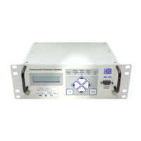
OVERCURRENT PROTECTION SYSTEM
Brand: Basler
|
Category: Protection Device
|
Size: 7.49 MB
Table of Contents
-
-
Features11
-
Description11
-
Clock14
-
General17
-
Irig19
-
Power Supply25
-
Display25
-
CE Qualified26
-
Case Size27
-
Weight27
-
Vibration27
-
Shock27
-
Environment27
-
-
-
Introduction39
-
Outputs45
-
-
Introduction53
-
Command68
-
Reclosing90
-
SP-60FL Command100
-
Mode 6, Latch102
-
SL-X62 Command103
-
SL-BF Command105
-
SP-BF Command106
-
Virtual Switches106
-
-
-
Current113
-
Frequency113
-
Introduction113
-
Voltage113
-
Apparent Power114
-
Power Factor114
-
Reactive Power114
-
True Power114
-
M Command115
-
M-I Command116
-
M-PF Command116
-
M-S Command116
-
M-V Command116
-
M-3V0 Command117
-
M-SYNC Command117
-
M-VAR Command117
-
M-WATT Command117
-
-
-
Clock121
-
Introduction121
-
IRIG Port121
-
SG-ID Command121
-
RG-DATE Command122
-
SG-CLK Command122
-
Co-Out (A12345)123
-
Input (1234)123
-
Output (A12345)123
-
Active Group124
-
Active Logic124
-
Breaker (52)124
-
CO-Group124
-
Diag/Alarm124
-
Recloser (79)124
-
Energy Data126
-
RE-KWH Command126
-
Demand Functions127
-
RE Command127
-
RE-KVAR Command127
-
SG-DI Command128
-
RD-PI Command129
-
RD-TI/YI Command129
-
RD-PVAR Command130
-
RD-PWATT Command130
-
SA-DI Command131
-
SB-LOGIC Command132
-
RB Command133
-
RB-DUTY Command136
-
SB-DUTY Command136
-
Breaker Alarms137
-
SA-BKR Command137
-
RD-LOG Command138
-
SG-LOG Command138
-
Fault Reporting140
-
Logic140
-
Pickup140
-
Trip140
-
Targets141
-
SG-TARG Command142
-
RG-TARG Command143
-
SG-LINE Command143
-
RO Command147
-
SG-OSC Command147
-
RS Command149
-
Alarms Function150
-
RA Command153
-
RG-VER Command154
-
SA-RESET Command154
-
-
-
Introduction156
-
Logic Schemes161
-
-
-
Introduction170
-
BUS Logic Scheme171
-
-
Introduction247
-
Ports247
-
Serial Port247
-
Command Summary255
-
Report Commands256
-
Setting Command259
-
-
-
Mounting269
-
CT Polarity284
-
Terminal Blocks284
-
Settings298
Advertisement
Basler BE1-951 Instruction Manual (505 pages)
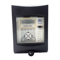
OVERCURRENT PROTECTION SYSTEM
Brand: Basler
|
Category: Surge Protector
|
Size: 12.73 MB
Table of Contents
-
-
-
-
Description15
-
Features15
-
General20
-
Irig22
-
Power Supply29
-
Display30
-
Isolation30
-
CE Qualified31
-
Environment31
-
Shock31
-
Vibration31
-
Weight31
-
-
-
-
-
-
Introduction47
-
Outputs54
-
-
-
Introduction63
-
-
-
-
Logic Timers115
-
-
Mode 6, Latch118
-
-
Virtual Switches138
-
-
-
Introduction147
-
-
Auto Ranging147
-
Voltage149
-
Current149
-
Power Factor150
-
Apparent Power150
-
True Power150
-
-
-
-
Introduction153
-
Clock154
-
Energy Data158
-
Demand Functions159
-
Fault Reporting176
-
Alarms Function190
-
Settings Compare197
-
-
-
Introduction201
-
-
-
Introduction213
-
-
-
Application Tips259
-
-
-
-
ACCESS Command295
-
HELP Command295
-
EXIT Command296
-
-
Introduction293
-
Serial Port293
-
RS-232 Ports293
-
RS-485 Port293
-
-
Command Summary301
-
-
-
-
General321
-
Mounting322
-
-
CT Polarity340
-
Terminal Blocks340
-
-
-
-
General363
-
-
Periodic Testing364
-
-
Test Equipment365
-
Power up367
-
Communications368
-
Control Outputs369
-
-
-
Periodic Testing376
-
-
Basler BE1-951 Application Manual (28 pages)
Generator Protection
Brand: Basler
|
Category: Protection Device
|
Size: 1.06 MB
Advertisement
