Basler BE1-951 Instruction Manual
Overcurrent protection system
Hide thumbs
Also See for BE1-951:
- Application manual (28 pages) ,
- Manual (13 pages) ,
- Instruction manual (424 pages)

Subscribe to Our Youtube Channel
Related Manuals for Basler BE1-951


Summary of Contents for Basler BE1-951
- Page 1 INSTRUCTION MANUAL OVERCURRENT PROTECTION SYSTEM BE1-951 Publication: 9328900990 Revision: L 06/07...
- Page 3 INTRODUCTION This instruction manual provides information about the operation and installation of the BE1-951 Overcurrent Protection System. To accomplish this, the following information is provided: • General information, specifications, and a Quick Start guide. • Functional description and setting parameters for the inputs and outputs, protection and control functions, metering functions, and reporting and alarm functions.
- Page 4 June 2007 CONFIDENTIAL INFORMATION of Basler Electric, Highland Illinois, USA. It is loaned for confidential use, subject to return on request, and with the mutual understanding that it will not be used in any manner detrimental to the interest of Basler Electric.
- Page 5 REVISION HISTORY The following information provides a historical summary of the changes made to the BE1-951 hardware, firmware, and software. The corresponding revisions made to this instruction manual (9328900990) are also summarized. Revisions are listed in reverse chronological order. BESTCOMS Software...
- Page 6 Improved stability of the 32 function for 0 power conditions (120 volts, 0 amps). • Enhanced operation of 62 timers for settings over 10 seconds. • Enhanced setting group switch initiated by the 79 reclosing function. BE1-951 Introduction 9328900990 Rev L...
- Page 7 Enhanced reporting of the firmware version and increased number of relay ID characters. • 2.52.01, 10/01 Added real-time clock with 8 hour capacitor backup on all BE1-951 version 2 relays. • Added support for 4,000 point load profile demand log.
- Page 8 Version and Date Change • 1.50.00, 04/00 This version was released to provide major upgrades to the original functionality provided by the BE1-951 and was mailed to all purchasers. • Added support (metering and recording) for optional VX, Auxiliary Voltage input sensing.
- Page 9 • D, 03/01 Updated Section 4 to reflect the changes in the protection and control elements. • Updated the remaining sections of the manual in accordance to the relays new functions. 9328900990 Rev L BE1-951 Introduction...
- Page 10 60FL function. • A combined index for both volumes was placed at the end of each volume. • Minor revisions and corrections were made throughout the manual. • —, 10/99 Initial release. viii BE1-951 Introduction 9328900990 Rev L...
-
Page 11: Table Of Contents
SECTION 13 • TESTING AND MAINTENANCE ..................13-1 SECTION 14 • BESTCOMS SOFTWARE ....................14-1 APPENDIX A • TIME OVERCURRENT CHARACTERISTIC CURVES ........... A-1 APPENDIX B • COMMAND CROSS-REFERENCE ................. B-1 APPENDIX C • TERMINAL COMMUNICATION..................C-1 9328900990 Rev L BE1-951 Introduction... - Page 12 This page intentionally left blank. BE1-951 Introduction 9328900990 Rev L...
-
Page 13: Section 1 • General Information
Phase AC Voltage Inputs ......................... 1-15 Auxiliary AC Voltage Inputs......................1-15 Analog to Digital Converter ......................1-15 Power Supply ........................... 1-15 Output Contacts ..........................1-15 Control Inputs ........................... 1-15 Communication Ports ........................1-16 Display.............................. 1-16 9328900990 Rev L BE1-951 General Information... - Page 14 GOST-R Certification ........................1-17 DNP Certification ..........................1-17 Environment ............................. 1-17 Shock..............................1-17 Vibration ............................1-17 Weight .............................. 1-17 Case Sizes ............................1-17 Figures Figure 1-1. Style Chart ..........................1-7 Tables Table 1-1. Burden ............................ 1-16 BE1-951 General Information 9328900990 Rev L...
-
Page 15: Section 1 • General Information
SECTION 1 • GENERAL INFORMATION DESCRIPTION The BE1-951 Overcurrent Protection System is an economical, microprocessor based, multifunction system that is available in a drawout, H1 (half-rack), S1, and S1 double-ended packages. BE1-951 features include: • • Directional Three-Phase Overcurrent Protection Automatic Reclosing •... -
Page 16: Protection And Control Functions
27P, 47, 59P, and the 51/27 function (60FL). Directional Power Protection One directional power element (32) is included in the BE1-951 and can be set for forward or reverse power protection. The relay can be used for any application requiring directional power flow detection... -
Page 17: Metering Functions
Virtual Lockout Protection The BE1-951 includes two virtual lockout functions (86 and 186) that emulate electric reset lockout relays and operate as a simple flip/flop. When the trip input is asserted, the output of the function toggles to the true state and when the reset input is asserted, the output of the function toggles to the false state. -
Page 18: Bestlogic Programmable Logic
BESTlogic Programmable Logic Each BE1-951 protection and control function is implemented in an independent function element. Every function block is equivalent to its single function, discrete device counterpart so it is immediately familiar to the protection engineer. Each independent function block has all of the inputs and outputs that the discrete component counterpart might have. -
Page 19: Write Access Security
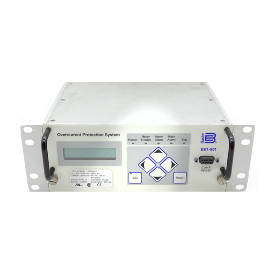
Security settings only affect write access. Read access is always available in any area through any port. Human-Machine Interface (HMI) Each BE1-951 comes with a front panel display with five LED indicators for Power Supply Status, Relay Trouble Alarm, Minor Alarm, Major Alarm, and Trip. The lighted, liquid crystal display (LCD) allows the relay to replace local indication and control functions such as panel metering, alarm annunciation, and control switches. -
Page 20: Model And Style Number Description
Sample Style Number Style number identification chart, Figure 1-1, defines the electrical characteristics and operational features included in BE1-951 Relays. For example, if the style number were E3N1H0Y, the device would have the following characteristics and features: BE1-951... -
Page 21: Operational Specifications
Figure 1-1. Style Chart OPERATIONAL SPECIFICATIONS BE1-951 relays have the following features and capabilities. Metered Current Values and Accuracy Current Range 0.5 to 15 0.1 to 3.0 Accuracy: ±1% of reading, ±1 least significant digit at 25°C ≤ ±0.02% per °C... -
Page 22: Calculated Values And Accuracy
8 to 24 hours, depending on conditions Battery: Greater than 5 years. Backup Battery (Optional): Lithium battery 3.6 Vdc, 0.95 AH (Basler P/N: 9 3187 00 012 or Applied Power P/N: BM551902) IRIG Supports IRIG Standard 200-98, Format B002 Input Signal:... -
Page 23: Contact Inputs Recognition Time
±2% or ±50 mA 1 Ampere CT: ±2% or ±10 mA Current Pickup Accuracy, Negative-Sequence (50TQ, 150TQ): Dropout/pickup ratio: 95% or higher 5 Ampere CT: ±3% or ±75 mA 1 Ampere CT: ±3% or ±15 mA 9328900990 Rev L BE1-951 General Information... -
Page 24: Directional Element (67)
Zero-Sequence Voltage (Requires 4W VT) Zero-Sequence Current (Requires IG) Negative-Sequence Volts/HZ (24) Pickup: 0.5 - 6V/Hz Delay Time: Inverse Squared Curve − = Time Trip = Time Dial, Trip Actual V/Hz Pickup V/Hz 1-10 BE1-951 General Information 9328900990 Rev L... -
Page 25: Directional Power (32, 132)
0.050 to 600 seconds Increment: 1 millisecond from 0 to 999 milliseconds 0.1 second from 1.0 to 9.9 seconds 1 second from 10 to 600 seconds Accuracy: ±0.5% or ±1 cycle whichever is greater 9328900990 Rev L BE1-951 General Information 1-11... -
Page 26: Auxiliary Undervoltage Function (27X)
0.050 to 600 seconds Increment: 1 millisecond from 0 to 999 milliseconds 0.1 second from 1.0 to 9.9 seconds 1 second from 10 to 60 seconds Accuracy: ±0.5% or ±1 cycle whichever is greater 1-12 BE1-951 General Information 9328900990 Rev L... -
Page 27: Auxiliary Overvoltage Function (59X, 159X)
±0.5% or +1¾, -0 cycles, whichever is greater Breaker Fail Timer (BF) Current Detector Pickup: Fixed at 0.5 A for 5 A unit, 0.1 A for 1 A unit Current Detector Pickup Accuracy: ±2% Delay Range: 50 to 999 milliseconds 9328900990 Rev L BE1-951 General Information 1-13... -
Page 28: General Purpose Timers (62, 162)
Continuous Rating: One Second Rating: 80 A For other current levels, use the formula: ½ I = (K/t) where t = time in seconds, K = 160,000 (S1 case), K = 90,000 (H1 case) 1-14 BE1-951 General Information 9328900990 Rev L... -
Page 29: Phase Ac Voltage Inputs
26 - 100 V 125/250* Vac/Vdc Power Supply: 69 - 200 V 24 Vdc Power Supply: Approx. 5 Vdc *Above voltage ranges depend on Jumper configurations. See Section 3, Input and Output Functions, Contact Sensing Inputs. 9328900990 Rev L BE1-951 General Information 1-15... -
Page 30: Communication Ports
(Excluding across open output contacts due to installed surge suppression components) Radio Frequency Interference (RFI) Qualified to IEEE C37.90.2-1995 Standard for Withstand Capability of Relays Systems to Radiated Electromagnetic Interference from Transceivers. 1-16 BE1-951 General Information 9328900990 Rev L... -
Page 31: Electrostatic Discharge (Esd)
Approximately 11.2 pounds (5.08 kg) S1 Double-ended: Approximately 12.8 pounds (5.81 kg) Case Sizes H1, S1 & S1 Double-ended: See Section 12, Installation, for case dimensions and Figure 1-1, Style Chart, for available options. 9328900990 Rev L BE1-951 General Information 1-17... - Page 32 This page intentionally left blank. 1-18 BE1-951 General Information 9328900990 Rev L...
-
Page 33: Section 2 • Quick Start
Output Logic Settings ......................... 2-3 USER INTERFACES ..........................2-3 Front Panel HMI ..........................2-3 ASCII Command Communications..................... 2-4 BESTCOMS for BE1-951, Graphical User Interface................2-5 GETTING STARTED ..........................2-6 Entering Test Settings ........................2-6 Checking the State of Inputs ......................2-7 Testing.............................. - Page 34 This page intentionally left blank. BE1-951 Quick Start 9328900990 Rev L...
-
Page 35: Section 2 • Quick Start
This section provides an overview of the BE1-951 Utility Multifunction Relay. You should be familiar with the concepts behind the user interfaces and BESTlogic before you begin reading about the detailed BE1- 951 functions. Sections 3 through 6 in the instruction manual describe each function of the BE1-951 in detail. -
Page 36: Bestlogic
BESTlogic Each of the protection and control functions in the BE1-951 is implemented as an independent function block that is equivalent to a single function, discrete device counterpart. Each independent function block has all of the inputs and outputs that the discrete component counterpart might have. Programming BESTlogic is equivalent to choosing the devices required by your protection and control scheme and drawing schematic diagrams to connect the inputs and outputs to obtain the desired operational logic. -
Page 37: Output Logic Settings
USER INTERFACES Two user interfaces are provided for interacting with the BE1-951 relay: one is the front panel HMI and the other is ASCII communications. The front panel HMI provides access to a subset of the total functionality of the device. -
Page 38: Ascii Command Communications
5. Scroll right to the 47 SETTINGS (Screen 5.3.4) and then down to reach the 47 pickup and time delay settings (Screen 5.3.4.1). Figure 2-2. Menu Screens Numbering Example ASCII Command Communications The BE1-951 relay has three independent communications ports for serial communications. A computer ® ® terminal or PC running a terminal emulation program such as Windows... -
Page 39: Bestcoms For Be1-951, Graphical User Interface
In batch download type operations, the user creates an ASCII text file of commands and sends it to the relay. To facilitate this process, the response from a multiple read command is output from the BE1-951 in command format. So the user need only enter S for Set (with no subgroup) and the relay responds with all of the setting commands and their associated parameters. -
Page 40: Getting Started
The BE1-951 measures the A phase, B phase, and C phase current magnitudes and angles directly from the three current sensing inputs. The neutral, positive, and negative-sequence magnitudes and angles are calculated from the fundamental component of each of the three-phase currents. -
Page 41: Checking The State Of Inputs
The answer to the question is yes and no. In general, once the fault goes away the output contacts open. The BE1-951 does offer an option to ensure that the contact will stay closed for at least 200 milliseconds. See Section 3, Input and Output Functions for additional information on that function. - Page 42 BE1-951 spreadsheets that are available from the Basler Electric web site, http://www.basler.com, in the Download Section under Software Tools. Does the BE1-951 have a battery installed as the back-up power source for the internal clock on loss of power? As an option, battery backup can be included.
- Page 43 13.) Can the IRIG signal be daisy-chained to multiple BE1-IPS100 units? Yes, multiple BE1-951 units can use the same IRIG-B input signal by daisy chaining the BE1- 951 inputs. The burden data is nonlinear, approximately 4 kilo-ohms at 3.5 Vdc and 3 kilo-ohms at 20 Vdc.
- Page 44 This page intentionally left blank. 2-10 BE1-951 Quick Start 9328900990 Rev L...
-
Page 45: Section 3 • Input And Output Functions
Figure 3-7. Inputs and Outputs Screen, Outputs 1-5, A Tab..............3-10 Tables Table 3-1. Measurement Functions Settings..................... 3-5 Table 3-2. Contact Sensing Turn-On Voltage ................... 3-6 Table 3-3. Digital Input Conditioning Settings ................... 3-7 Table 3-4. Hold Timer Settings........................ 3-10 9328900990 Rev L BE1-951 Input and Output Functions... - Page 46 This page intentionally left blank. BE1-951 Input and Output Functions 9328900990 Rev L...
-
Page 47: Section 3 • Input And Output Functions
BE1-951 outputs. Each input and output is isolated and terminated at separate terminal blocks. This section describes the function and setup of each input and output and provides the equations that the BE1-951 uses for calculating the power quantities. -
Page 48: Power Measurement
Power system frequency is monitored on the A phase voltage input or the AB voltage input when in three- wire mode. When the applied voltage is greater than 10 volts, the BE1-951 measures the frequency. The measured frequency is used by the 81 function and applies to all measurements and calculations. -
Page 49: Measurement Functions Setup
Measurement Functions Setup The BE1-951 requires information about the power system and its current and voltage transformers to provide metering, fault reporting, fault location, and protective relaying. This information is entered using BESTCOMS. Alternately, it may be entered at the HMI (see Section 10, Human-Machine Interface) or through the communication port using the following ASCII commands: SG-CT, SG-VTP, SG-VTX, SG- FREQ, SG-NOM, and SG-PHROT. - Page 50 Figure 3-2. General Operation Screen, CT & VT Setup CT Ratio. The BE1-951 requires setting information on the CT ratio. These settings are used by the metering and fault reporting functions to display measured quantities in primary units. Sec. Amps is used to select secondary CT amps.
-
Page 51: Contact Sensing Inputs
Nominal voltage(s) of the external dc source(s) must fall within the relay dc power supply input voltage range. To enhance user flexibility, the BE1-951 relay uses wide range AC/DC power supplies that cover several common control voltage ratings. To further enhance flexibility, the input circuits are designed to respond to voltages at the lower end of the control voltage range while not overheating at the high end of the control voltage range. -
Page 52: Digital Input Conditioning Function
138 – 200 Vac or Vdc Each BE1-951 is delivered without the contact-sensing jumpers installed for operation in the higher end of the control voltage range. If the contact sensing inputs are to be operated at the lower end of the control voltage range, the jumpers must be installed. - Page 53 Debounce Time. The labels include a label to describe the input, a label to describe the Energized State, and a label to describe the De-Energized State. Labels are used by the BE1-951's reporting functions. To edit the settings or labels, select Inputs and Outputs from the Screens pull-down menu. Then select the Inputs 1-4 tab.
-
Page 54: Outputs
OUTPUTS BE1-951 relays have five general-purpose output contacts (OUT1 through OUT5) and one fail-safe, normally closed/open (when de-energized), alarm output contact (OUTA). Each output is isolated and rated for tripping duty. OUT1 through OUT5 are Form A (normally open), and OUTA is Form A or B (normally closed/open depending on style number). -
Page 55: Retrieving Output Status
Reporting, for more information. Relay Trouble Alarm Disable When the BE1-951 self-diagnostics function detects a relay problem, an internal alarm condition (ALMREL) is set. This alarm condition disables the outputs and de-energizes the OUTA relay, closing/opening (depending on style number) the OUTA contact. For more details about this function see Section 6, Reporting and Alarm Functions, Alarms Function. -
Page 56: Output Logic Override Control
Pulsing an Output Contact Pulsing BE1-951 outputs provides the same function as the push-to-energize feature of other Basler Electric solid-state relays. This feature is useful when testing the protection and control system. When pulsed, an output contact changes from the current state (as determined by the virtual output logic expression) to the opposite state for 200 milliseconds. - Page 57 2. Test all outputs by pulsing momentarily. >CS-OUT=P OUT=P SELECTED >CO-OUT=P OUT=P EXECUTED 3. Disable the trip output (OUT1) by holding it at logic 0. >CS-OUT1=0 OUT1=0 SELECTED >CO-OUT1=0 OUT1=0 EXECUTED 9328900990 Rev L BE1-951 Input and Output Functions 3-11...
- Page 58 (0) or closed (1) state. A P indicates that the contact is being pulsed and will return to logic control automatically. See Section 6, Reporting and Alarm Functions, General Status Reporting, for more information. 3-12 BE1-951 Input and Output Functions 9328900990 Rev L...
-
Page 59: Section 4 • Protection And Control
BESTlogic Settings for Negative-Sequence Overvoltage ............4-43 Operating Settings for Negative-Sequence Overvoltage ............. 4-44 FREQUENCY PROTECTION......................4-46 81 - Over/Under Frequency Protection .................... 4-46 BESTlogic Settings for Over/Under Frequency ................4-47 Operating Settings for Over/Under Frequency ................4-48 9328900990 Rev L BE1-951 Protection and Control... - Page 60 Figure 4-3. Input Control Mode 1....................... 4-4 Figure 4-4. Input Control Mode 2....................... 4-5 Figure 4-5. Automatic Operation Based on Load Change ................ 4-6 Figure 4-6. Automatic Operation Based on Cold Load Pickup..............4-7 BE1-951 Protection and Control 9328900990 Rev L...
- Page 61 Figure 4-63. BESTlogic Function Element Screen, 25................4-68 Figure 4-64. Voltage Protection Screen, 25 Tab ..................4-69 Figure 4-65. 25VM Logic ......................... 4-71 Figure 4-66. 60FL Element........................4-71 Figure 4-67. 60FL Element Logic ......................4-72 9328900990 Rev L BE1-951 Protection and Control...
- Page 62 Table 4-45. BESTlogic Settings for Virtual Breaker Control Switch ............4-80 Equations Equation 4-1. Restraint Pickup Level ...................... 4-21 Equation 4-2. Time OC Characteristics for Trip ..................4-21 Equation 4-3. Time OC Characteristics for Reset ................... 4-21 BE1-951 Protection and Control 9328900990 Rev L...
-
Page 63: Section 4 • Protection And Control
SECTION 4 • PROTECTION AND CONTROL INTRODUCTION The BE1-951 provides many functions that can be used to protect and control power system equipment in and around a protected zone. BE1-951 protection functions include: • Instantaneous Overcurrent with Settable Time Delay (50TP, 50TN, 50TQ, 150TP, 150TN, 150TQ) •... -
Page 64: Bestlogic Settings For Setting Group Control
SGCON time setting. This output can be used in the programmable alarms function if it is desired to monitor when the BE1-951 changes to a new setting group. See Section 6, Reporting and Alarm Functions, Alarms Function for more information on using alarm outputs. - Page 65 Logic Expression. When TRUE, automatic control is enabled and Automatic when FALSE, logic control is enabled. Example 1. Make the following settings to the setting group selection logic. Refer to Figure 4-2. Mode: Discrete Inputs AUTOMATIC: /IN2 9328900990 Rev L BE1-951 Protection and Control...
- Page 66 AUTO input. Note that a pulse on the D1 input while D0 is also active doesn't cause a setting change to SG3 because the AUTO input is active. BE1-951 Protection and Control 9328900990 Rev L...
-
Page 67: Automatic Setting Group Control
"return time.” However, if the "switch-to" threshold is 0 and a non-zero switch-to time is entered, then the relay changes to the indicated setting group and falls below 10% of nominal (0.5 A / 0.1 A for 5 A / 1 A 9328900990 Rev L BE1-951 Protection and Control... - Page 68 The threshold for this is 10% nominal rating of the relay current input. BE1-951 Protection and Control 9328900990 Rev L...
-
Page 69: Group Control By Monitoring Reclose Status
GROUP1 = ,,,,791 will cause the relay to change from Setting Group 0 to Setting Group 1 after the first reclose, but not until the relay senses the breaker has actually closed. This may be best understood by examining the diagram in the following example. 9328900990 Rev L BE1-951 Protection and Control... - Page 70 P0002-08 BREAKER STATUS 10-14-03 Open RESET 79RTD 79RTD 79RTD 79RTD 79RTD TIMER RESET 791TD 792TD 793TD 794TD LOCKOUT RESET Recloser STEP Figure 4-8. Example 2, Error in Setting Group Control by Recloser Shot BE1-951 Protection and Control 9328900990 Rev L...
-
Page 71: Group Control By Monitoring Fuse Loss Status
Setting Group Selection function. To open the Setting Group Selection screen, select Setting Group Selection from the Screens pull-down menu. Alternately, settings may be made using the SP-GROUP ASCII command. 9328900990 Rev L BE1-951 Protection and Control... - Page 72 0 = Disabled below the Return Threshold setting. Percentage of the SG0 Monitor Setting that the Return 0 to 150 monitored current must decrease below in order for a Threshold return to SG0. 4-10 BE1-951 Protection and Control 9328900990 Rev L...
-
Page 73: Logic Override Of The Setting Group Control Function
<mode> entry of CS-GROUP command and CO-GROUP command must match or setting group selection will be rejected. If more than 30 seconds elapse after issuing a CS-GROUP command, the CO-GROUP command will be rejected. 9328900990 Rev L BE1-951 Protection and Control 4-11... -
Page 74: Retrieving Setting Group Control Status From The Relay
Logic override cannot be determined using BESTCOMS. OVERCURRENT PROTECTION The BE1-951 includes instantaneous elements for Phase, Neutral, and Negative-Sequence, as well as time overcurrent elements for phase, neutral or ground, and negative-sequence. 50T - Instantaneous Overcurrent Protection with Settable Time Delay... -
Page 75: Bestlogic Settings For Instantaneous Overcurrent
Enable the 50T or 150T function by selecting its mode of operation from the Mode pull-down menu. To connect the element's inputs, select the button for the corresponding input in the BESTlogic Function Element screen. The BESTlogic Expression Builder screen will open. Select the expression type to be 9328900990 Rev L BE1-951 Protection and Control 4-13... -
Page 76: Operating Settings For Instantaneous Overcurrent
3 Phase Residual BLK: NOTE If the BE1-951 has 5 ampere phase inputs and a 1 ampere independent ground input, the valid pickup setting range of the neutral overcurrent functions will depend on the logic mode setting which designates whether the three-phase residual or the independent ground input is to be monitored. - Page 77 Milliseconds 0.1 for 0.1 to 9.9 Seconds 0.1 to 60 seconds Time 1.0 for 10 to 60 Seconds 0 to 3600 cycles (60 Hz) ∗ Cycles 0 to 2500 cycles (50 Hz) 9328900990 Rev L BE1-951 Protection and Control 4-15...
-
Page 78: Retrieving Instantaneous Overcurrent Status From The Relay
Reporting, for more information. The status cannot be determined by using BESTCOMS. 51 - Time Overcurrent Protection BE1-951 relays have one element for phase (51P), two elements for neutral (51N and 151N), and one element for negative-sequence (51Q) inverse time overcurrent protection. Figure 4-14 shows the 51 elements. -
Page 79: Bestlogic Settings For Time Overcurrent
The BESTlogic settings for Time Overcurrent are provided in Table 4-6. These settings enable an element by attaching it to the CT input circuits and provide blocking control as determined by the logic expression assigned to the block input. 9328900990 Rev L BE1-951 Protection and Control 4-17... -
Page 80: Operating Settings For Time Overcurrent
Logic pull-down menu at the top of the screen before BESTlogic settings can be changed. See Section 7, BESTlogic Programmable Logic. To the right of the Logic pull-down menu is a pull-down 4-18 BE1-951 Protection and Control 9328900990 Rev L... -
Page 81: Voltage Restraint/Control For Time Overcurrent Protection
27R threshold setting), the overcurrent pickup level for that phase will be reduced to 83% of its setting. When set for this mode of operation, the 51P pickup setting is typically set above worst case, load current levels. 9328900990 Rev L BE1-951 Protection and Control 4-19... -
Page 82: Operating Settings For Voltage Restraint/Control For Time Overcurrent
S<g>-27R ASCII commands or from the HMI Screen 5.x.7.5 where x equals 1 for Setting Group 0, 2 for Setting Group 1, 3 for Setting Group 2, and 4 for Setting Group 3. 4-20 BE1-951 Protection and Control 9328900990 Rev L... -
Page 83: Programmable Curves
Curves. When time current characteristic curve P is selected, the coefficients used in the equation are those defined by the user. Definitions for these equations are provided in Table 4-10. Equation 4-2. Time OC Characteristics for Trip Equation 4-3. Time OC Characteristics for Reset − − 9328900990 Rev L BE1-951 Protection and Control 4-21... -
Page 84: Setting Programmable Curves
Programmable curve coefficients can be entered regardless of the curve chosen for the protection element. However, the programmable curve will not be enabled until P is selected as the curve for the protective element. Figure 4-18. Curve Coefficients Screen 4-22 BE1-951 Protection and Control 9328900990 Rev L... -
Page 85: 46 Curve
(for ground faults). To establish a simple, consistent methodology for providing a forward or reverse directional decision in the BE1-951, an internal “angle adjustment factor” of 180 degrees was included in the V2 and V0 voltage calculations. As a result, an in-phase condition (0 degrees) between the positive, negative, and zero-sequence component voltages and currents will result in “forward fault detection”... -
Page 86: Polarizing Settings For 67N Directional Overcurrent Element
S#-67N ASCII command. To the right of the Logic pull-down menu is a pull-down menu labeled Settings. The Settings menu is used to select the setting group that the element’s settings apply to. Figure 4-19. Overcurrent Protection Screen, 67N Polarization Tab 4-24 BE1-951 Protection and Control 9328900990 Rev L... - Page 87 The directional algorithm requires the power line impedance parameters. These parameters are input into the BE1-951 using BESTCOMS, the SG-LINE ASCII command or HMI Screens 6.3.10 through 6.3.12. Table 4-13 provides the power line impedance settings. Table 4-13. Power Line Impedance Settings...
-
Page 88: Negative-Sequence Overcurrent Protection
Angle compensation is not required for current polarization since the polarizing quantity IG is inherently compensated. Internally, the BE1-951 also uses several constant limits to determine if the system levels are adequate to perform reliable directional tests and set directional bits. See Table 4-14. -
Page 89: Negative-Sequence Coordination Settings
To plot the negative- sequence time current characteristics on the same plot for the ground devices, you need to multiply the pickup value by the multiplier for phase-to-ground faults. 9328900990 Rev L BE1-951 Protection and Control 4-27... -
Page 90: Delta/Wye Transformer Application
46 curve should be set at a value below 0.50 A. Continuous (I ratings for generators are typically in the range of 3 to 15 percent of their full-load current rating. 4-28 BE1-951 Protection and Control 9328900990 Rev L... -
Page 91: Directional Power Protection
DIRECTIONAL POWER PROTECTION 32 - Directional Power Protection Figure 4-22 illustrates the inputs and outputs of the Directional Power element. The BE1-951 provides one such element: 32. Element operation is described in the following paragraphs. Figure 4-22. Directional Power Logic Block The Directional Overpower element has two outputs: PU (pickup) and T (trip). -
Page 92: Operating Settings For Directional Power
Directional Power, select Power Protection from the Screens pull-down menu. Alternately, settings may be made using the S<g>-32 ASCII command where g equals the setting group number or the HMI interface using Screen 5.x.4.1 where x equals the setting group number. 4-30 BE1-951 Protection and Control 9328900990 Rev L... - Page 93 0.0 to 600 seconds Time 1.0 for 10 to 600 Seconds 3 to 36,000 cycles (60 Hz) ∗ Cycles 2.5 to 30,000 cycles (50 Hz) F = Forward Direction R = Reverse 9328900990 Rev L BE1-951 Protection and Control 4-31...
-
Page 94: Voltage Protection
Direction: Reverse VOLTAGE PROTECTION BE1-951 voltage protection includes elements for overexcitation, phase undervoltage, phase overvoltage, auxiliary overvoltage, auxiliary undervoltage, and negative-sequence overvoltage. 24 - Volts per Hertz Overexcitation Protection Figure 4-25 illustrates the inputs and outputs of the Volts per Hertz element. Element operation is described in the following paragraphs. -
Page 95: Bestlogic Settings For Volts Per Hertz Overexcitation
BESTCOMS screen used to select BESTlogic settings for the overexcitation element. To open the screen, select Voltage Protection from the Screens pull-down menu and select the 24 tab. Then select The BESTlogic button. Alternately, settings may be made using the SL-24 ASCII command. 9328900990 Rev L BE1-951 Protection and Control 4-33... -
Page 96: Operating Settings Volts Per Hertz Overexcitation
Voltage Protection from the Screens pull-down menu and select the 24 Tab. Alternately, settings may be made using S<g>-24 and SA-24 ASCII command or through HMI Screen 5.x.1.1 where x represents the number of the setting group. 4-34 BE1-951 Protection and Control 9328900990 Rev L... -
Page 97: Programmable Alarm For Volts Per Hertz Overexcitation
Table 4-20 lists the programmable alarm settings for Volts per Hertz Overexcitation. Table 4-20. Programmable Alarm Settings for Volts per Hertz Overexcitation Setting Range Increment Unit of Measure Default Alarm Level 0 – 120 % of pickup level 9328900990 Rev L BE1-951 Protection and Control 4-35... -
Page 98: 27P/59P - Phase Undervoltage/Overvoltage Protection
(The 59P Time Overvoltage is set in a similar manner once the 59P tab is selected.) To open the screen, select Voltage Protection from the Screens pull-down menu, and select the 27P tab. Alternately, settings may be made using the SL-27P (undervoltage) and SL-59P (overvoltage) ASCII commands. 4-36 BE1-951 Protection and Control 9328900990 Rev L... - Page 99 Logic expression that disables function when TRUE. Example 1. Make the following BESTlogic settings to the 27P element. Refer to Figure 4-30. Mode: All 3 of 3 Phases BLK: IN4 + VO6 9328900990 Rev L BE1-951 Protection and Control 4-37...
-
Page 100: Operating Settings For Phase Undervoltage/Overvoltage
It is also selectable for seconds, minutes, and cycles. Using the pull-down menus and buttons, make the application appropriate settings to the undervoltage and overvoltage elements. Operating settings for Phase Undervoltage/Overvoltage are summarized in Table 4-22. 4-38 BE1-951 Protection and Control 9328900990 Rev L... -
Page 101: 27X/59X - Auxiliary Undervoltage/Overvoltage Protection
If the voltage remains above the pickup threshold for the duration of the time delay setting, the trip output becomes TRUE. If the voltage decreases below the 59X/159X dropout ratio of 98% or increases above the 27X dropout ratio of 100%, the timer is reset to zero. 9328900990 Rev L BE1-951 Protection and Control 4-39... -
Page 102: Bestlogic Settings For Auxiliary Undervoltage/Overvoltage
Save when finished to return to the BESTlogic Function Element screen. For more details on the BESTlogic Expression Builder, see Section 7, BESTlogic Programmable Logic. Select Done when the settings have been completely edited. BESTlogic settings for Auxiliary Undervoltage/Overvoltage are summarized in Table 4-23. 4-40 BE1-951 Protection and Control 9328900990 Rev L... -
Page 103: Operating Settings For Auxiliary Undervoltage/Overvoltage
Under/Overvoltage elements, select Voltage Protection from the Screens pull-down menu. Then select the 59X/159X tab. (The Auxiliary Undervoltage [27X] element is set in a similar manner using the 27X tab.) Alternately, settings may be made using the S<g>-59X, S<g>-159X, and S<g>-27X ASCII commands. 9328900990 Rev L BE1-951 Protection and Control 4-41... - Page 104 Increment precision after conversion is limited to that appropriate for each of those units of measure. Example 1. Make the following changes to the 59X element. Refer to Figure 4-34. Pickup: 75 secondary volts Time: 50 ms 4-42 BE1-951 Protection and Control 9328900990 Rev L...
-
Page 105: 47 - Negative-Sequence Overvoltage Protection
Overvoltage with Settable Time Delay function. To open the screen, select Voltage Protection from the Screens pull-down menu and then select the 47 tab. Then select the BESTlogic button at the bottom of the screen. Alternately, settings may be made using the SL-47 ASCII command. 9328900990 Rev L BE1-951 Protection and Control 4-43... -
Page 106: Operating Settings For Negative-Sequence Overvoltage
Voltage Protection from the Screens pull-down menu and then select the 47 tab. Alternately, settings maybe made using the S<g>-47 ASCII command or through the HMI interface using Screen 5.x.5.1 where x represents the number of the setting group. 4-44 BE1-951 Protection and Control 9328900990 Rev L... - Page 107 0.01 cycles from the ASCII command interface. Time delays entered in cycles are converted to milliseconds or seconds. Increment precision after conversion is limited to that appropriate for each of those units of measure. 9328900990 Rev L BE1-951 Protection and Control 4-45...
-
Page 108: Frequency Protection
AB voltage input when in three-wire mode. Power system frequency is measured on the optional auxiliary voltage input as well. When the applied voltage is greater than 10 volts, the BE1-951 measures the frequency. The measured frequency is the average of two cycles of measurement. -
Page 109: Bestlogic Settings For Over/Under Frequency
Table 4-28. BESTlogic Settings for Over/Under Frequency Function Range/Purpose Default 0 = Disabled Mode 1 = Enabled on VP Input X = Enabled on VX Input Logic expression that disables function when TRUE. 9328900990 Rev L BE1-951 Protection and Control 4-47... -
Page 110: Operating Settings For Over/Under Frequency
The voltage inhibit setting unit of measure depends upon the VTP and VTX connection settings. For 4- wire or PN connections it is secondary VPN. For 3-wire or PP connections it is secondary VPP. 4-48 BE1-951 Protection and Control 9328900990 Rev L... -
Page 111: Breaker Failure Protection
BREAKER FAILURE PROTECTION 50BF - Breaker Failure Protection BE1-951 relays provide one function block for breaker failure protection. This function includes a timer and a current detector. Figure 4-41 shows the BF function block. The function block has two outputs BFPU (breaker failure pickup) and BFT (breaker failure trip). -
Page 112: Bestlogic Settings For Breaker Failure
BESTlogic Function Element screen for Breaker Failure, select Breaker Failure from the Screens pull-down menu. Then select the BESTlogic button. Alternately, settings may be made using the SL-BF ASCII command. 4-50 BE1-951 Protection and Control 9328900990 Rev L... - Page 113 Logic expression that enables function when TRUE. Block Logic expression that disables function when TRUE. Example 1. Make the following BESTlogic settings to the Breaker Failure element. Refer to Figure 4-42. Mode: Enable Initiate: Block: 9328900990 Rev L BE1-951 Protection and Control 4-51...
-
Page 114: Operating Settings For Breaker Failure
EEPROM first by entering E;Y. Using the pull-down menus and buttons, make the application appropriate settings to the Breaker Failure element. 4-52 BE1-951 Protection and Control 9328900990 Rev L... -
Page 115: Retrieving Breaker Failure Status From The Relay
62 - General Purpose Logic Timers BE1-951 relays provide two general-purpose logic timers that are extremely versatile. Each can be set for one of five modes of operation to emulate virtually any type of timer. Each function block has one output (62 or 162) that is asserted when the timing criteria has been met according to the BESTlogic mode setting. -
Page 116: Mode 1, Pu/Do (Pickup/Dropout Timer)
This mode of operation is similar to the one shot nonretriggerable mode, except that if a new FALSE-to- TRUE transition occurs on the INITIATE input expression, the output is forced to logic FALSE and the timing sequence is restarted. See Figure 4-47. 4-54 BE1-951 Protection and Control 9328900990 Rev L... -
Page 117: Mode 4, Oscillator
TRUE. Then at some time later, the initiate expression becomes FALSE and stays FALSE for the duration of RESET time T2. At that point, the output of the timer is toggled FALSE. 9328900990 Rev L BE1-951 Protection and Control 4-55... -
Page 118: Mode 6, Latch
BESTlogic Function Element screen for Logic Timer, select Logic Timers from the Screens pull- down menu. Then select the BESTlogic button for either the 62 or the 162 element. Alternately, settings may be made using the SL-x62 ASCII command. 4-56 BE1-951 Protection and Control 9328900990 Rev L... - Page 119 Logic expression that initiates timing sequence. Logic expression that disables function when TRUE. Example 1. Make the following settings to the 62 Logic Timer. Figure 4-51 illustrates these settings. Logic: User Mode: One Shot Non-Retrig Initiate: Block: 9328900990 Rev L BE1-951 Protection and Control 4-57...
-
Page 120: Operating Settings For General Purpose Logic Timers
0.01 cycles from the ASCII command interface. Time delays entered in cycles are converted to milliseconds or seconds. Increment precision after conversion is limited to that appropriate for each of those units of measure. 4-58 BE1-951 Protection and Control 9328900990 Rev L... -
Page 121: Retrieving 62/162 Output Status Information From The Relay
RECLOSING The BE1-951 reclosing function provides up to four reclosing attempts that can be initiated by a protective trip or by one of the contact sensing inputs. The reclosers allow supervisory control and coordination of tripping and reclosing with other system devices. Any of the four recloser shots can be used to select a different setting group when the appropriate shot is reached in a reclosing sequence. -
Page 122: Breaker Status (Status)
This output becomes TRUE when either the 52 status input OR the 79C input is TRUE AND the sequence operation (shot counter) matches one of the programmed steps of the S<g>-79SCB command. Figure 4-55 illustrates 79SCB logic. Figure 4-55. 79SCB Logic 4-60 BE1-951 Protection and Control 9328900990 Rev L... -
Page 123: Bestlogic Settings For Reclosing
Save when finished to return to the BESTlogic Function Element screen. For more details on the BESTlogic Expression Builder, see Section 7, BESTlogic Programmable Logic. Select Done after the settings have been completely edited. Table 4-34 summarizes the BESTlogic settings for Reclosing. 9328900990 Rev L BE1-951 Protection and Control 4-61... -
Page 124: Operating Settings For Reclosing
7, BESTlogic Programmable Logic. To the right of the Logic pull-down menu is a pull-down menu labeled Settings. The Settings menu is used to select the setting group that the element’s settings apply to. 4-62 BE1-951 Protection and Control 9328900990 Rev L... -
Page 125: Reclosing Fail Timer (79F)
S#-79SCB command. A 0 (zero) disables the 79SCB output. This setting can be changed on the Reclosing screen in BESTCOMS. See Figure 4-57. 9328900990 Rev L BE1-951 Protection and Control 4-63... -
Page 126: Zone-Sequence Coordination
To coordinate tripping and reclosing sequences with downstream protective relays and reclosers, the BE1-951 senses fault current from downstream faults when a user programmable logic, set by the SP- 79ZONE command, picks up and then drops out without a trip output (defined with the SG-TRIGGER command) occurring. - Page 127 If the zone pickup logic becomes TRUE and then FALSE without a trip output operating, then the 79 automatic reclose counter should be incremented. The Max Cycle timer resets the shot counter. Figure 4-61 illustrates an overall logic diagram for the recloser function. 9328900990 Rev L BE1-951 Protection and Control 4-65...
- Page 128 Figure 4-61. Overall Logic Diagram for Reclosing 4-66 BE1-951 Protection and Control 9328900990 Rev L...
-
Page 129: Synchronism-Check Protection
The BE1-951 compares the VTP voltage magnitude and angle to the VTX voltage magnitude and angle to determine synchronism. Therefore, proper connection of the VT inputs is vital to the correct operation of the 25 function. -
Page 130: Bestlogic Settings For The Sync-Check Element
BESTlogic Function Element screen for the Sync-Check element, select Voltage Protection from the Screens pull-down menu. Then select the BESTlogic button. Alternately, settings may be made using SL-25 ASCII command. Figure 4-63. BESTlogic Function Element Screen, 25 4-68 BE1-951 Protection and Control 9328900990 Rev L... -
Page 131: Operating Settings For Synchronism-Check
Voltage Protection from the Screens pull-down menu. Alternately, settings may be made using the S<g>- 25 ASCII command or through the HMI using Screens 5.x.2.1 through 5.x.2.4 where g and x equals the setting group number. Figure 4-64. Voltage Protection Screen, 25 Tab 9328900990 Rev L BE1-951 Protection and Control 4-69... -
Page 132: 25Vm - Voltage Monitor
0.050 - 60 0.1 for 1.0 to 9.9 Seconds 1 for 10 to 60 0 = Disabled 1 – 3, 12, 13, 23, 123 0 = Disabled 1 – 3, 12, 13, 23, 123 4-70 BE1-951 Protection and Control 9328900990 Rev L... -
Page 133: Voltage Transformer Fuse Loss Detection
60FL - Fuse Loss Detection BE1-951 relays have one 60FL element that can be used to detect fuse loss or loss of potential in a three-phase system. The 60FL element is illustrated in Figure 4-66. When the element logic becomes TRUE, the 60FL logic output becomes TRUE. -
Page 134: Fuse Loss Detection Blocking Settings
60FL element. Select Reporting and Alarms from the Screens pull-down menu and select the VT Monitor tab. Alternately, settings may be made using the SP-60FL ASCII command. See Section 11, ASCII Command Interface, Command Summary, Protection Setting Commands, for more information. 4-72 BE1-951 Protection and Control 9328900990 Rev L... - Page 135 Similarly, zero-sequence voltage polarization can only be performed if 3P4W sensing is selected. The following qualifiers are applied to the voltage polarized ground direction element based on the user selected input quantity: 9328900990 Rev L BE1-951 Protection and Control 4-73...
-
Page 136: Virtual Lockout Protection
VIRTUAL LOCKOUT PROTECTION 86 - Virtual Lockout Protection BE1-951 virtual lockout protection consists of two protection elements: 86 and 186. Each element has three available inputs that are BESTlogic programmable. The element can be enabled or disabled using the Mode input. In addition to the Mode input, the 86 element also has a Trip input and Reset input. All three of these inputs are BESTlogic programmable. - Page 137 Logic expression that determines when and how the Reset element will be reset. Example 1. Make the following BESTlogic settings to the lockout function. Refer to Figure 4-70. Mode: Enable Trip: Reset: 9328900990 Rev L BE1-951 Protection and Control 4-75...
-
Page 138: Virtual Switches
VIRTUAL SWITCHES 43 - Virtual Selector Switches BE1-951 relays have four virtual selector switches that can provide manual control, locally and remotely, without using physical switches and/or interposing relays. Each virtual switch can be set for one of three modes of operation to emulate virtually any type of binary (two position) switch. An example would be an application that requires a recloser or 51N ground cutoff. -
Page 139: Select Before Operate Control Of Virtual Selector Switches
CS-x43 (control select-virtual switch) and CO-x43 (operate select- virtual switch). This is not possible through BESTCOMS. A state change takes place immediately without having to execute an EXIT – SAVE settings command. 9328900990 Rev L BE1-951 Protection and Control 4-77... -
Page 140: Retrieving Virtual Selector Switches Status From The Relay
HMI and remotely from a substation computer or modem connection to an operator’s console. D2861-06 08-05-99 Figure 4-73. 101 Function Block 4-78 BE1-951 Protection and Control 9328900990 Rev L... -
Page 141: Bestlogic Settings For Virtual Breaker Control Switch
Switches from the Screens pull-down menu. Then select the BESTlogic button in for the 101 element. Alternately, setting may be made using the SL-101 ASCII command. Figure 4-75. BESTlogic Function Element Screen, 101 9328900990 Rev L BE1-951 Protection and Control 4-79... -
Page 142: Select Before Operate Control Of Virtual Breaker Control Switch
The returned setting indicated that the switch is in the after-close state. Example 2. Trip the breaker by closing the trip output of the virtual control switch. >CS-101=T 101=T SELECTED >CO-101=T 101=T EXECUTED 4-80 BE1-951 Protection and Control 9328900990 Rev L... -
Page 143: Retrieving Virtual Breaker Control Switch Status From The Relay
HMI Screen 2.2.1 provides switch control and also displays the current status of the virtual control switches (after-trip or after-close). As the previous Example 1 demonstrated, the state of the virtual breaker control switch can be determined using the CO-101 command in a read-only mode. 9328900990 Rev L BE1-951 Protection and Control 4-81... - Page 144 This page intentionally left blank. 4-82 BE1-951 Protection and Control 9328900990 Rev L...
-
Page 145: Section 5 • Metering
Figure 5-1. Metering Screen........................5-2 Figure 5-2. Relationship of Slip Frequency and Sync Angle to Synchroscope......... 5-3 Tables Table 5-1. Auto Ranging Scales for Metered Values ................5-1 Table 5-2. Metering Functions Summary ....................5-2 9328900990 Rev L BE1-951 Metering... - Page 146 This page intentionally left blank. BE1-951 Metering 9328900990 Rev L...
-
Page 147: Section 6 • Metering
Section 3, Input and Output Functions, Power System Inputs, Power Measurement. Energy measurement is covered in Section 6, Reporting and Alarm Functions. Auto Ranging The BE1-951 automatically scales metered values. Table 5-1 illustrates the ranges for each value metered. Table 5-1. Auto Ranging Scales for Metered Values... - Page 148 Current, A-phase M-IA Current, B-phase M-IB Current, C-phase M-IC Current, Ground M-IG Current, Neutral M-IN Current, Negative-Sequence M-IQ Power, True M-WATT Power, True, Three-phase M-WATT3 Power, True, A-phase M-WATTA 3.8.1 Power, True, B-phase M-WATTB 3.8.2 BE1-951 Metering 9328900990 Rev L...
-
Page 149: Voltage
3.11 Voltage The BE1-951 meters A-phase voltage, B-phase voltage, C-phase voltage, voltage across phases A and B, phases B and C, and phases A and C. Negative-sequence voltage and three-phase zero-sequence (residual) voltage are also metered. The VTP connection determines what is measured. For the auxiliary voltage input, fundamental (Vx) and 3 harmonic voltages (V3X) are measured. -
Page 150: Power Factor
+1,500 kilovars. True Power True power is metered over a range of –7,500 kilowatts to +7,500 kilowatts on five-ampere nominal systems. One-ampere nominal systems meter true power over a range of –1,500 watts to +1,500 watts. BE1-951 Metering 9328900990 Rev L... -
Page 151: Section 6 • Reporting And Alarm Functions
Figure 6-12. BESTlogic Function Element Screen, Fault Recording ............6-25 Figure 6-13. Reporting and Alarms Screen, Fault Recording Tab ............6-27 Figure 6-14. Target Reset Logic......................6-27 Figure 6-15. Metering Screen........................6-28 9328900990 Rev L BE1-951 Reporting and Alarm Functions... - Page 152 Table 6-21. Programmable Alarm Settings ..................... 6-41 Equations Equation 6-1. Energy Data Equation ......................6-6 Equation 6-2. Dmax Set by Number of Operations ................. 6-17 Equation 6-3. Dmax Set Using Square Root Factor................6-17 BE1-951 Reporting and Alarm Functions 9328900990 Rev L...
-
Page 153: Section 6 • Reporting And Alarm Functions
(or mapped). RELAY IDENTIFIER INFORMATION BE1-951 relays have two relay Circuit Identification fields: Relay ID and Station ID. These fields are used in the header information lines of the Fault Reports, the Oscillograph Records, and the Sequence of Events Records. -
Page 154: Clock
CLOCK The BE1-951 provides a real-time clock with capacitor backup that is capable of operating the clock for up to eight hours after power is removed from the relay. The clock is used by the demand reporting function, the fault reporting function, the oscillograph recording function, and the sequence of events recorder function to time-stamp events. -
Page 155: Reading And Setting The Clock
>RG-TIME = 11:24P00 GENERAL STATUS REPORTING BE1-951 relays have extensive capabilities for reporting relay status. This is important for determining the health and status of the system for diagnostics and troubleshooting. Throughout this manual, reference is made to the RG-STAT (report general, status) report and the appropriate HMI screens for determining the status of various functions. -
Page 156: General Status Report
These two lines report the status of each BESTlogic variable. These lines can be entered into Table 6-3 to determine the status of each logic variable. Section 7, BESTlogic Programmable Logic, provides more information about BESTlogic variables. BE1-951 Reporting and Alarm Functions 9328900990 Rev L... - Page 157 If the command RG is entered by itself, the relay reports the time, date, target information, and other reports in the following example. RG-VER and RG-STAT commands have multiple line outputs and these are not read at the RG command. 9328900990 Rev L BE1-951 Reporting and Alarm Functions...
-
Page 158: Energy Data
RG-TARG=NONE ENERGY DATA Energy information in the form of watt-hours and var-hours is measured and reported by the BE1-951. Both positive and negative values are reported in three-phase, primary units. Watt-hour and var-hour values are calculated per minute as shown in Equation 6-1. -
Page 159: Demand Functions
SA-DI (setting alarm, demand current) command. Demand reporting is setup using the SG-DI (setting general, demand interval) command. Demand reporting settings are summarized in Table 6-4. 9328900990 Rev L BE1-951 Reporting and Alarm Functions... -
Page 160: Retrieving Demand Reporting Information
This can be done by pressing the Edit key. Write access to the Reports functional area is required to preset values at the HMI. Values and time stamps in the demand registers can also be read through the communication ports by using the RD (report demands) command. BE1-951 Reporting and Alarm Functions 9328900990 Rev L... - Page 161 Syntax: RD-PI<x>[=0] Comments: x =A/B/C/N/Q, where A, B, and C represent A, B and C-phase, N represents neutral and Q represents negative-sequence. A setting of 0 (RD-PI<p>=0) resets the peak demand values. 9328900990 Rev L BE1-951 Reporting and Alarm Functions...
- Page 162 Reads today's (TWATT) or yesterday's (YWATT) watt demand values. Syntax: RD-TWATT or RD-YWATT Comments: Two watt demand values are returned. The first value is the peak positive demand; the second value is the peak negative demand. 6-10 BE1-951 Reporting and Alarm Functions 9328900990 Rev L...
-
Page 163: Overload And Unbalance Alarms
SA-DI Command Example: Example 1. Set the demand alarm thresholds at six amperes for A, B and C phase current; and three amperes for neutral and negative-sequence current. >SA-DIP=6.0; SA-DIN=3.0; SA-DIQ=3.0 9328900990 Rev L BE1-951 Reporting and Alarm Functions 6-11... -
Page 164: Optional Load Profile Recording Function
Optional Load Profile Recording Function Load profile recording is an optional selection when the BE1-951 is ordered. This option (4000 Point Load Profile Demand Log or Y as the third character from the right in the style chart) uses a 4,000-point data array for data storage. -
Page 165: Setting Fuse Loss Block Logic
To open the screen shown in Figure 6-4, select Reporting and Alarms, from the Screens pull-down menu. Then select the VT Monitor tab. Alternately; settings may be made using the SP-60FL ASCII command. 9328900990 Rev L BE1-951 Reporting and Alarm Functions 6-13... -
Page 166: Breaker Monitoring
Monitoring tab. Then select the Logic button in the lower left hand corner of the screen and inside the box labeled, Breaker Status Logic. Alternately, settings may be made using the SB-LOGIC ASCII command. 6-14 BE1-951 Reporting and Alarm Functions 9328900990 Rev L... - Page 167 Write access to the reports functions must be gained to edit this value at the HMI. Breaker operations can be read or set through the communication ports using the RB- OPCNTR (report breaker, operations counter) command. 9328900990 Rev L BE1-951 Reporting and Alarm Functions 6-15...
-
Page 168: Breaker Duty Monitoring
(D ). The approach to set DMAX is to select the maximum number of operations at some current level and enter D calculated by the equation: 6-16 BE1-951 Reporting and Alarm Functions 9328900990 Rev L... - Page 169 OR logic term (e.g., IN1 or VO7) which blocks the breaker monitoring logic when TRUE (1). BLKBKR is set to zero to disable blocking. When breaker monitoring is blocked (logic expression equals 1), breaker duty is not accumulated. 9328900990 Rev L BE1-951 Reporting and Alarm Functions 6-17...
- Page 170 (When SG-TRIGGER (PU) is TRUE) flashing Red TRIP LED (When SG-TRIGGER (Trip) is TRUE) solid Breaker interruption duty D2849-09.vsd 05-26-99 Setting group (When SG-TRIGGER (PU) is TRUE) change blocked Figure 6-6. Protective Fault Analysis 6-18 BE1-951 Reporting and Alarm Functions 9328900990 Rev L...
- Page 171 Breaker Duty Monitoring function. To open the Breaker Duty Monitoring screen, select Reporting and Alarms from the Screens pull-down menu. Then select the Breaker Monitoring tab. Alternately; settings may be made using the SB-DUTY ASCII command. 9328900990 Rev L BE1-951 Reporting and Alarm Functions 6-19...
- Page 172 Select Save when finished to return to the BESTlogic Function Element screen. For more details on the BESTlogic Expression Builder, See Section 7, BESTlogic Programmable Logic. Select Done when the settings have been completely edited. Figure 6-8. BESTlogic Function Element Screen, Breaker Duty Monitoring 6-20 BE1-951 Reporting and Alarm Functions 9328900990 Rev L...
-
Page 173: Breaker Alarms
Three alarm points are included in the programmable alarms for checking breaker monitoring functions. Each alarm point can be programmed to monitor any of the three breaker monitoring functions, operations counter, interruption duty, or clearing time. An alarm threshold can be programmed to monitor 9328900990 Rev L BE1-951 Reporting and Alarm Functions 6-21... -
Page 174: Trip Circuit Monitor
(see Table 6-11). Figure 6-10 illustrates typical trip circuit monitor connections for the BE1-951. If the breaker status reporting function detects a closed breaker and no trip circuit... - Page 175 If the trip circuit voltage is significantly greater than the power supply voltage (for example, when using a capacitor trip device), the user should program the BE1-951 to use one of the other output relays for tripping. In this situation, the trip circuit monitor function will not be available.
-
Page 176: Fault Reporting
Fault Reporting Expressions and Settings The fault reporting function records and reports information about faults that have been detected by the relay. The BE1-951 provides many fault reporting features. These features include Fault Summary Reports, Sequence of Events Recorder Reports, Oscillographic Records, and Targets. - Page 177 OR and NOT operators in the Boolean logic equation. Example 1. Make the following BESTlogic settings to the Fault Recording function. Refer to Figure 6-12. Tripped: BFT+VO11 Picked up: 79LO+VO12 Logic: 79SCB 9328900990 Rev L BE1-951 Reporting and Alarm Functions 6-25...
-
Page 178: Targets
To open the Reporting and Alarms, Fault Recording tab, select Reporting and Alarms from the Screens pull-down menu. Then select the Fault Recording tab. Enable the targets by checking the appropriate boxes. 6-26 BE1-951 Reporting and Alarm Functions 9328900990 Rev L... - Page 179 Pressing the HMI Reset key will clear these targets and the Trip LED. Password access is not required to reset targets at the HMI. See Figure 6-14. TRSTKEY Figure 6-14. Target Reset Logic 9328900990 Rev L BE1-951 Reporting and Alarm Functions 6-27...
- Page 180 Logic Timers 67T ABC Q, N or G; 167T ABC, N or G Directional Time Overcurrents Directional Instantaneous 67/167 ABC, Q or 1, N or G Overcurrents 81/181/281/381/481/581 Frequency Breaker Failure 6-28 BE1-951 Reporting and Alarm Functions 9328900990 Rev L...
-
Page 181: Distance To Fault
150AN Distance to Fault The BE1-951 calculates distance to fault each time a fault record is triggered. Distance to fault is calculated and displayed based on the power line parameters entered using BESTCOMS, the HMI, or with the SG-LINE command. Table 6-16 provides the power line operating settings. - Page 182 Therefore, the data would be entered as: >SG-LINE = 4.7,60,15.9,70,10 The BE1-951 calculates distance to fault each time a fault record is triggered. Refer to the fault record triggering logic command SG-TRIGGER for triggering details. Distance to fault is calculated and displayed based on the power line parameters.
-
Page 183: Fault Summary Reports
A computed value greater than maximum line length is reported as N/A (not applicable). Fault Summary Reports The BE1-951 records information about faults and creates fault summary reports. A maximum of 16 fault summary reports are stored in the relay. The two most recent reports are stored in nonvolatile memory. - Page 184 Breaker Failure: A fault was detected as defined by the pickup expression and the breaker failure trip became TRUE before the fault was cleared. • RF=TRIG: A fault report was recorded by the ASCII command interface. 6-32 BE1-951 Reporting and Alarm Functions 9328900990 Rev L...
- Page 185 Read or reset fault report data. Syntax: RF-<n/NEW>=<0/TRIG> Comments: n = fault record number (1 to 255) NEW = newest fault record since all records were last reset using RG=0 RF Command Example: Example 1. >RF 9328900990 Rev L BE1-951 Reporting and Alarm Functions 6-33...
-
Page 186: Oscillographic Records
5 cycles of sample data in its buffer until the fault is cleared. At that point, it freezes the 5-cycle buffer, providing 5 cycles of end of fault data. 6-34 BE1-951 Reporting and Alarm Functions 9328900990 Rev L... - Page 187 OK. The Fault Record Filenames screen (Figure 6-20) will appear. Type the base filename in the first row. The rest of the filenames will respond by changing to match the base filename. Select OK to save the file. 9328900990 Rev L BE1-951 Reporting and Alarm Functions 6-35...
-
Page 188: Sequence Of Events Recorder
Software for IBM compatible computers is available from Basler Electric to convert binary files to ASCII format. The download protocol may be either XMODEM or XMODEM CRC format. For ease of reference, the name of the downloaded file should be the same as the command. -
Page 189: Retrieving Ser Information
RS Command Purpose: Read/Reset Sequence of Events record data. Syntax: RS-<n>, RS-F<id>, RS-AL, RS-IO, RS-NEW Comments: <n> = number of events to be retrieved <id> = fault record number to be retrieved 9328900990 Rev L BE1-951 Reporting and Alarm Functions 6-37... -
Page 190: Alarms Function
VO5 logic expression at /0 (SL-VO5=/0). A not zero setting is equal to logic 1. When the relay is fully functional, the OUT5 output contact is closed. Since all output relays are disabled when a relay trouble alarm exists, OUT5 opens when relay trouble occurs. 6-38 BE1-951 Reporting and Alarm Functions 9328900990 Rev L... -
Page 191: Major, Minor, And Logic Programmable Alarms
Reclose fail timer timed out before breaker closed. RECLOSER LOCKOUT ∗ Recloser went through sequence without success. Breaker Alarm 1 threshold (SA-BKR1 setting) BREAKER ALARM 1 exceeded. Breaker Alarm 2 threshold (SA-BKR1 setting) BREAKER ALARM 2 exceeded. 9328900990 Rev L BE1-951 Reporting and Alarm Functions 6-39... - Page 192 Programming details for Demand alarm points is available in the Demand Functions subsection. Refer to the Breaker Monitoring subsection for details about programming Breaker alarm points. Major, Minor, and Logic programmable alarm settings are made using BESTCOMS. To select 6-40 BE1-951 Reporting and Alarm Functions 9328900990 Rev L...
- Page 193 DIAG/ALARM line of the General Status Report. Refer to the General Status Reporting subsection for more information about obtaining relay status with the RG-STAT command. Figure 6-22 shows the alarm reset logic. 9328900990 Rev L BE1-951 Reporting and Alarm Functions 6-41...
- Page 194 Syntax: RA-<type>={0} Comments: type = LGC (Logic), MAJ (Major), MIN (Minor) or REL (Relay). <=0> means clear the latched alarm. Privilege G or R password access is required to reset alarms. 6-42 BE1-951 Reporting and Alarm Functions 9328900990 Rev L...
-
Page 195: Links Between Programmable Alarms And Bestlogic
Then select the Alarms tab. Select the Logic button in the BESTlogic box on the right side of the screen. Refer to Figure 6-21. The BESTlogic Function Element screen for Alarm Reset Logic will appear. See Figure 6-24. Figure 6-24. BESTlogic Function Element Screen, Alarm Reset Logic 9328900990 Rev L BE1-951 Reporting and Alarm Functions 6-43... -
Page 196: Hardware And Software Version Reporting
The ID tab displays the software version number, the serial number, and circuit identification labels. The General Information tab is shown in Figure 6-25. Figure 6-25. General Operation Screen, General Information Tab 6-44 BE1-951 Reporting and Alarm Functions 9328900990 Rev L... -
Page 197: Settings Compare
If there are any differences in the two files, a dialog box will pop up notifying you that Differences Are Found. The BESTCOMS Settings Compare dialog box pops up (Figure 6-27) where you can select to Show All or Show Diffs. Figure 6-27. BESTCOMS Settings Compare Dialog Box 9328900990 Rev L BE1-951 Reporting and Alarm Functions 6-45... - Page 198 This page intentionally left blank. 6-46 BE1-951 Reporting and Alarm Functions 9328900990 Rev L...
-
Page 199: Section 7 • Bestlogic Programmable Logic
Figure 7-5. BESTlogic Expression Builder Screen..................7-6 Figure 7-6. BESTlogic Screen, Logic Select Tab ..................7-8 Tables Table 7-1. Logic Variable Names and Descriptions .................. 7-4 Table 7-2. Programmable Variable Name Setting..................7-9 9328900990 Rev L BE1-951 BESTlogic Programmable Logic... - Page 200 This page intentionally left blank. BE1-951 BESTlogic Programmable Logic 9328900990 Rev L...
-
Page 201: Introduction
LOGIC INTRODUCTION Multifunction relays such as the BE1-951 Overcurrent Protection System are similar in nature to a panel of single-function protective relays. Both must be wired together with ancillary devices to operate as a complete protection and control system. In the single-function static and electromechanical environment, elementary diagrams and wiring diagrams provide direction for wiring protective elements, switches, meters, and indicator lights into a unique protection and control system. - Page 202 Figure 7-1. BESTlogic Function Blocks BE1-951 BESTlogic Programmable Logic 9328900990 Rev L...
- Page 203 Figure 7-2. BESTlogic Function Blocks - continued 9328900990 Rev L BE1-951 BESTlogic Programmable Logic...
- Page 204 Loss of Potential Alarm Lockout Protection 27XPU 27 Auxiliary Undervoltage Picked Up 47 Negative-Sequence Tripped 86 Output 47PU 47 Negative-Sequence Picked Up 186 Output 59PT 59 Phase Overvoltage Tripped 59PPU 59 Phase Overvoltage Picked Up BE1-951 BESTlogic Programmable Logic 9328900990 Rev L...
-
Page 205: Function Block Logic Settings
When the logic is running and logic expression SL-VO[n] is FALSE, then output VO[n] = 0. When the logic is running and logic expression SL-VO[n] is TRUE, then VO[n] = 1. Hardware outputs OUTA and OUT1 through OUT5 follow the corresponding logic outputs VOA and VO1 through VO5. 9328900990 Rev L BE1-951 BESTlogic Programmable Logic... - Page 206 A virtual output exists only as a logical state inside the relay. A hardware output is a physical relay contact that can be used for protection or control. Each BE1-951 relay has five isolated, normally open (NO) output contacts (OUT1 - OUT5) and one isolated, normally closed (NC) alarm output (OUTA). Output contacts OUT1 through OUT5 are controlled by the status of the internal virtual logic signals VO1 through VO5.
-
Page 207: The Active Logic Scheme
The default, active logic scheme for the BE1-951 is named BASIC-OC. If the function block configuration and output logic of BASIC-OC meets the requirements of your application, then only the operating settings (power system parameters and threshold settings) need to be adjusted before placing the relay in service. -
Page 208: Custom Logic Schemes
Always remove the relay from service prior to changing or modifying the active logic scheme. Attempting to modify a logic scheme while the relay is in service could generate unexpected or unwanted outputs. BE1-951 BESTlogic Programmable Logic 9328900990 Rev L... -
Page 209: Copying And Renaming Preprogrammed Logic Schemes
Input and output logic variable names are assigned by typing them into the appropriate text box on the related BESTCOMS screen. All of the BE1-951’s inputs, outputs, and 43 switches have labels that can be edited. Table 7-2 shows the range and purpose of each label. Alternately, labels may be edited using the SN ASCII command. -
Page 210: Bestlogic Application Tips
(described previously). With this feature, a logic condition can be designed and used for an alarm. The virtual output label would then be reported in the Reporting and Alarm functions. 7-10 BE1-951 BESTlogic Programmable Logic 9328900990 Rev L... -
Page 211: Section 8 • Application
BUS Logic Settings and Equations ....................8-40 BACKUP Logic Settings and Equations................... 8-46 MISCELLANEOUS LOGIC EXPRESSIONS ..................8-46 APPLICATION TIPS ..........................8-47 Trip Circuit and Voltage Monitor....................... 8-47 Output Contact Latch using the TRSTKEY Logic Variable .............. 8-48 9328900990 Rev L BE1-951 Application... - Page 212 Alarm Latch and Pseudo Target Using the ARSTKEY Logic Variable ..........8-49 Under Frequency Load Shedding with Restoration Permissive............8-50 BE1-951 Logic Equations and Settings, Underfrequency Load Shedding........8-53 Close Circuit Monitor ........................8-55 High-Speed Reclose ........................8-56 Block Load Tap Changer........................8-56 Block Neutral and Negative-Sequence Protection ................
-
Page 213: Section 8 • Application
SECTION 8 • APPLICATION INTRODUCTION This section discusses application of the BE1-951 Overcurrent Protection System using the preprogrammed logic schemes. The Details of Preprogrammed Logic Schemes subsection describes the characteristics of each logic scheme and how they combine to create an Overcurrent Protection System for a radial system substation. -
Page 214: Oc-W-79 Logic Scheme (Overcurrent Protection With Reclosing)
The components of BASIC-OC logic are summarized in Tables 8-1, 8-2, 8-3, and 8-4. Figure 8-1 shows a one-line drawing for the BASIC-OC logic scheme. A diagram of BASIC-OC logic is shown in Figure 8-2. BE1-951 Application 9328900990 Rev L... -
Page 215: Operation - Protection
Used for instantaneous phase overcurrent protection. 1 (enabled) 1 (3 Phase 50TN Used for instantaneous neutral overcurrent protection. Residual) Used for instantaneous negative-sequence overcurrent 50TQ 1 (enabled) protection. 150TP 0 (disabled) 150TN 0 (disabled) 150TQ 0 (disabled) 9328900990 Rev L BE1-951 Application... - Page 216 Input 2 Logic: No manual selection logic is used. GROUP Input Selection) Input 3 Logic: No manual selection logic is used. Auto/Manual Logic: Set to 1 (/0) to enable automatic selection. No manual selection is used. BE1-951 Application 9328900990 Rev L...
- Page 217 Timed Neutral and neutral or timed negative- 51N&QTRP TRIP NORMAL Negative-Sequence OC. sequence overcurrent condition (OUT5) exists. BESTlogic Expression: VO5=51NT+51QT TRUE FALSE BESTlogic Expression: VO6=0 TRUE FALSE BESTlogic Expression: VO7=0 TRUE FALSE BESTlogic Expression: VO8=0 9328900990 Rev L BE1-951 Application...
- Page 218 FALSE BESTlogic Expression: VO13=0 VO14 VO14 TRUE FALSE BESTlogic Expression: VO14=0 VO15 VO15 TRUE FALSE BESTlogic Expression: VO15=0 OUT1 TRIP OUT5 OUT3 50TP 50TN 50TQ OUT4 OUT2 D2849-02 BE1-951 07-14-99 Figure 8-1. BASIC-OC One-Line Drawing BE1-951 Application 9328900990 Rev L...
- Page 219 Figure 8-2. BASIC-OC Logic Diagram 9328900990 Rev L BE1-951 Application...
- Page 220 The components of OC-W-79 logic are summarized in Tables 8-5, 8-6, 8-7, and 8-8. Figure 8-3 shows a one-line drawing for the OC-W-79 logic scheme. A diagram of OC-W-79 logic is shown in Figure 8-4. BE1-951 Application 9328900990 Rev L...
-
Page 221: Operation - Protection
ASCII commands through a communication port. More information about alarms is provided in Section 6, Reporting and Alarm Functions. NOTE When using OUT1 through OUT5 as alarm outputs, remember that these outputs do not have normally closed, failsafe output contacts. 9328900990 Rev L BE1-951 Application... - Page 222 Block when disabled by IN4. /IN4 Residual) Block when disabled by IN4. /IN4 1 (enabled) 151N 0 (disabled) 0 (disabled) 0 (disabled) 0 (disabled) 0 (disabled) 159P 0 (disabled) 159X 0 (disabled) 0 (disabled) 0 (disabled) 0 (disabled) 8-10 BE1-951 Application 9328900990 Rev L...
- Page 223 Table 8-7. OC-W-79 Virtual Switch Logic State Labels Switch Purpose Mode Label True False 0 (Disable) SWITCH_43 CLOSED OPEN 0 (Disable) SWITCH_143 CLOSED OPEN 0 (Disable) SWITCH_243 CLOSED OPEN 0 (Disable) SWITCH_343 CLOSED OPEN 0 (Disable) 9328900990 Rev L BE1-951 Application 8-11...
- Page 224 NORMAL instantaneous elements trip. BESTlogic Expression: VO9=150TPT+150TNT+150TQT+/IN2 VO10 VO10 TRUE FALSE BESTlogic Expression: VO10=0 Protective Trip TRUE when any 50, 150, or 51 VO11 PROT_TRP TRIP NORMAL Expression. element times out. BESTlogic Expression: VO11=50TPT+50TNT+50TQT+150TPT+150TNT+150TQT+51PT+51NT+51QT 8-12 BE1-951 Application 9328900990 Rev L...
- Page 225 VO14 TRUE FALSE BESTlogic Expression: VO14=0 VO15 VO15 TRUE FALSE BESTlogic Expression: VO15=0 N &Q ENABLE OUT1 TRIP OUT2 50TP 50TN 50TQ BLOCK d2849-08 06-19-99 150TP 150TN 150TQ BE1-951 Figure 8-3. OC-W-79 One-Line Drawing 9328900990 Rev L BE1-951 Application 8-13...
- Page 226 Figure 8-4. OC-W-79 Logic Diagram 8-14 BE1-951 Application 9328900990 Rev L...
- Page 227 The components of OC-W-CTL logic are summarized in Tables 8-9, 8-10, 8-11, and 8-12. Figure 8-5 shows a one-line drawing for the OC-W-CTL logic scheme. A diagram of OC-W-CTL logic is shown in Figure 8-6. 9328900990 Rev L BE1-951 Application 8-15...
-
Page 228: Operation - Control
Note that some alarms are non-latching and will clear when the alarm condition goes away. Other alarms require a reset either by operating the front panel Reset pushbutton or by 8-16 BE1-951 Application 9328900990 Rev L... - Page 229 1 (enabled) 1 (3 Phase Block when disabled by IN4 or virtual switch 243. /IN4+243 Residual) Block when disabled by IN4 or virtual switch 243. /IN4+243 1 (enabled) 151N 0 (disabled) 0 (disabled) 0 (disabled) 9328900990 Rev L BE1-951 Application 8-17...
- Page 230 Auto/Manual switch for automatic setting 2 (On/Off) SETGRP_MAN MANUAL AUTO group change logic. Disable recloser when virtual switch is closed. 2 (On/Off) RCL_DISABL DISABLD ENABLED 2 (On/Off) N&Q_DISABL DISABLD ENABLED Disable neutral and negative sequence, 50 8-18 BE1-951 Application 9328900990 Rev L...
- Page 231 BESTlogic Expression: VO5=ALMMAJ TRUE FALSE BESTlogic Expression: VO6=0 TRUE FALSE BESTlogic Expression: VO7=0 TRUE when any protective element trips or when the Reclose Initiate. RCL_INI NORMAL external reclose initiate input is TRUE. BESTlogic Expression: VO8=VO11+IN3 9328900990 Rev L BE1-951 Application 8-19...
- Page 232 BESTlogic Expression: VO14=0 VO15 VO15 TRUE FALSE BESTlogic Expression: VO15=0 N &Q ENABLE OUT1 TRIP 50TP 50TN 50TQ OUT2 52CC BLOCK D2849-06 07-19-99 GROUP CONTROL 150TP 150TN 150TQ BE1-951 Figure 8-5. OC-W-CTL One-Line Diagram 8-20 BE1-951 Application 9328900990 Rev L...
- Page 233 Figure 8-6. OC-W-CTL Logic Diagram 9328900990 Rev L BE1-951 Application 8-21...
- Page 234 When used with other programmable relays using BUS and BACKUP logic schemes, FDR-W-IL logic provides protection when the feeder relay is out of service. Basler Electric protective relays that incorporate a BUS and BACKUP logic scheme are the BE1-851 Overcurrent...
-
Page 235: Normal Operation - Control
When any of the feeder relay overcurrent function blocks are picked up, OUT4 closes. The signal from OUT4 is intended for connection to IN2 of an upstream BE1-951 using BUS logic. When the upstream relay recognizes an external contact closure on IN2, the upstream relay will block its 50T elements that are set to trip the bus breaker or bus lockout relay (OUT3 of BUS relay). -
Page 236: Normal Operation - Alarms
Backup for relay failure can be implemented using the BUS and BACKUP preprogrammed logic schemes. These schemes are described in detail in the Bus and Backup Logic Schemes subsection. 8-24 BE1-951 Application 9328900990 Rev L... - Page 237 Block when disabled by IN3 or virtual switch 243. /IN3+243 1 (enabled) 151N 0 (disabled) 0 (disabled) 0 (disabled) 0 (disabled) 0 (disabled) 159P 0 (disabled) 159X 0 (disabled) 0 (disabled) 0 (disabled) 0 (disabled) 0 (disabled) 0 (disabled) 0 (disabled) 9328900990 Rev L BE1-951 Application 8-25...
- Page 238 Places the relay in Test mode so that breaker failure is disabled when virtual 2 (On/Off) TESTENABLE TSTMODE NORMAL switch is closed. Allows breaker to be tripped or closed 1 (Enable) manually from the HMI or ASCII interface. 8-26 BE1-951 Application 9328900990 Rev L...
- Page 239 Breaker Failure Trip. BKR_FAIL TRIP NORMAL protection times out. (OUT5) BESTlogic Expression: VO5=BFT TRUE FALSE BESTlogic Expression: VO6=0 TRUE FALSE BESTlogic Expression: VO7=0 TRUE when any protective Reclose Initiate. RCL_INI NORMAL element trips. BESTlogic Expression: VO8=VO11 9328900990 Rev L BE1-951 Application 8-27...
- Page 240 Indicates that the relay is in Test mode and that the breaker VO15 Alarm Mask 23. failure is disabled. TRUE if IN4 TEST_MODE TEST NORMAL is de-energized or if virtual switch 343 is closed. BESTlogic Expression: VO15=343+/IN4 8-28 BE1-951 Application 9328900990 Rev L...
- Page 241 N &Q ENABLE OUT1 TRIP 50TP 50TN 50TQ OUT2 52CC D2849-05 07-19-99 150TP 150TN 150TQ OUT5 BF OUT GROUP CONTROL OUT3 TEST TEST MODE MODE OUT BE1-951 Figure 8-7. FDR-W-IL One-Line Diagram 9328900990 Rev L BE1-951 Application 8-29...
- Page 242 Figure 8-8. FDR-W-IL Logic Diagram 8-30 BE1-951 Application 9328900990 Rev L...
-
Page 243: Bus And Backup Logic Schemes
(except for reclosing) for the feeder relays if they are out of service for testing or maintenance. Figure 8-9 illustrates how FDR-W-IL, BUS, and BACKUP relays are interconnected to achieve this integrated protection system. 9328900990 Rev L BE1-951 Application 8-31... -
Page 244: Normal Operation - Control
Virtual switches that are not needed may simply go unused. The contact sensing inputs can be freed up for other uses by utilizing the virtual switches for other control functions. 8-32 BE1-951 Application 9328900990 Rev L... -
Page 245: Normal Operation - Bus Protection
Contingency Operation - Backup Protection for Bus Breaker Failure Bus breaker-failure protection is provided by the main bus relay using the preprogrammed logic scheme BACKUP. OUT5 is configured as the breaker failure trip output. OUT5 can be wired to trip the upstream 9328900990 Rev L BE1-951 Application 8-33... -
Page 246: Contingency Operation - Backup Protection For Backup Relay Out Of Service
A bus fault will cause the BUS relay to trip the feeder breaker with the relay out of service because no blocking signal will be sent by any of the feeder relays. Since this won't clear the fault, the BACKUP relay will clear the fault with its 18 to 20-cycle coordination interval. 8-34 BE1-951 Application 9328900990 Rev L... - Page 247 150TQ 0 (disabled) 1 (enabled) 1 (3 Phase Residual) 1 (enabled) 151N 0 (disabled) 0 (disabled) 0 (disabled) 0 (disabled) 0 (disabled) 159P 0 (disabled) 159X 0 (disabled) 0 (disabled) 0 (disabled) 0 (disabled) 9328900990 Rev L BE1-951 Application 8-35...
- Page 248 Places the relay in Test mode and blocks BFI signal (VO3) to external Breaker Failure 2 (On/Off) TESTENABLE TSTMODE NORMAL Relay. Allows breaker to be tripped or closed 1 (Enable) manually from the HMI or ASCII interface. 8-36 BE1-951 Application 9328900990 Rev L...
- Page 249 Overcurrent Trip. overcurrent element trips. BESTlogic Expression: VO9=50TPT+50TNT+50TQT VO10 VO10 TRUE FALSE BESTlogic Expression: VO10=0 Protective Trip TRUE when any 50 or 51 VO11 PROT_TRP TRIP NORMAL Expression. element times out. BESTlogic Expression: VO11=50TPT+50TNT+50TQT+51PT+51NT+51QT 9328900990 Rev L BE1-951 Application 8-37...
- Page 250 Relay is shown in Normal mode (not in Test mode). 01-05-00 If the feeder relay is out of service, the 50T and 51 elements are diverted from OUT1 and OUT4 to OUT5 for feeder protection. Figure 8-10. BUS One-Line Diagram 8-38 BE1-951 Application 9328900990 Rev L...
- Page 251 Figure 8-11. BUS Logic Diagram 9328900990 Rev L BE1-951 Application 8-39...
- Page 252 State Labels Input Purpose Name Label Energized De-Energized 51b breaker status. BREAKER OPEN CLOSED Places relay in feeder backup mode when out of service feeder relay is detected by FEEDERS_OK NORMAL FDR_OOS open contact. 8-40 BE1-951 Application 9328900990 Rev L...
- Page 253 1 (enabled) 151N 0 (disabled) 0 (disabled) 0 (disabled) 0 (disabled) 0 (disabled) 159P 0 (disabled) 159X 0 (disabled) 0 (disabled) 0 (disabled) 0 (disabled) 0 (disabled) 0 (disabled) 0 (disabled) 0 (disabled) 0 (disabled) 9328900990 Rev L BE1-951 Application 8-41...
- Page 254 Places the relay in Test mode so that breaker failure is disabled when IN4 is de- 2 (On/Off) TESTENABLE TSTMODE NORMAL energized. Allows breaker to be tripped or closed 1 (Enable) manually from the HMI or ASCII interface. 8-42 BE1-951 Application 9328900990 Rev L...
- Page 255 Initiate breaker failure timing when protective trip expression is TRUE or when external VO10 Breaker Failure Initiate. SUPV-BFI BFI-INI NORMAL initiate contact is sensed and any of the fault detectors is picked up. BESTlogic Expression: VO10=VO11+IN3*150TNPU+IN3*150TNPU+IN3*150TQPU 9328900990 Rev L BE1-951 Application 8-43...
- Page 256 TRIP FEEDER RELAY OUT OF SERVICE GROUP OUT2 CONTROL 52CC OUT3 OUT OF SERVICE FEEDER OUT4 50TP 50TN 50TQ 150TP 150TN 150TQ TEST MODE OUT5 TRIP BE1-951 D2849-04 01-07-00 Figure 8-12. BACKUP One-Line Diagram 8-44 BE1-951 Application 9328900990 Rev L...
- Page 257 Figure 8-13. BACKUP Logic Diagram 9328900990 Rev L BE1-951 Application 8-45...
-
Page 258: Miscellaneous Logic Expressions
Each of the pre-programmed logic schemes is designed to be compatible with the factory default logic expression settings for these Reporting and Alarm functions. However, when copying a pre-programmed scheme into your logic settings for modification, it is important to recognize that settings will not be copied 8-46 BE1-951 Application 9328900990 Rev L... -
Page 259: Application Tips
Test Mode Enable Virtual Switch OUTPUT 1 = Enabled, 0 = Normal OUT5 LOGIC Breaker Failure Trip VO10 BREAKER FAILURE Breaker Failure BFPU (BF) Initiate Expression Figure 8-14. Trip Circuit Continuity and Voltage Monitor 9328900990 Rev L BE1-951 Application 8-47... -
Page 260: Output Contact Latch Using The Trstkey Logic Variable
On occasion, an application will call for latching an output contact such as simulating a lockout (86) function. Each output contact of a Basler relay can be set to latch by using an AND gate to seal the trip condition and the TRSTKEY logic variable to reset the latch. - Page 261 Using the same transformer protection application as in the previous example, the user wants to trip and lockout the high side circuit switcher for a Sudden Pressure Relay trip. The user also wants a sealed annunciation on the HMI that reads "SPR_TRIP". 9328900990 Rev L BE1-951 Application 8-49...
- Page 262 Also, reliability increases as the user is no longer depending on a single relay to sense the under frequency condition. If the BE1-951 is not available on every circuit or user philosophy requires a bus level installation, the BE1-951 can also be applied for bus level under frequency protection.
- Page 263 A one-shot, non-retriggerable timer (62), initiated by the last lockout to reset (Input 1), is used to automatically reset the BE1-951 targets and Trip LED via "logic" input to the Target Reset Logic. (See Figure 6-4). Fault and Event records detailing the operation are available from the relay.
- Page 264 As with the Bus Level Application, an optional "auto target reset circuit", can be initiated, automatically resetting the BE1-951 targets and Trip LED and eliminating the need for further operator input. A one- shot, non-retriggerable timer (62), initiated by VO10, REST_PER is used to automatically reset the BE1- 951 targets and Trip LED via "logic"...
- Page 265 BE1-951 Logic Equations and Settings, Underfrequency Load Shedding Bus UF Load Shed The following is an example of how to apply UF Load Shed logic at the Bus level. The logic can be applied in any number of ways including stand alone, to other preprogrammed schemes or completely customized by the user.
- Page 266 Add +81T+181T to BUS SG-TRIG Replace the ,0 with ,62 at the end of BUS SG-TARG The resulting OC-UF-79 setting logic is as follows: SL-50TP=1,79SCB; SL-50TN=1,79SCB+/IN4; SL-50TQ=1,79SCB+/IN4 SL-150TP=1,0; SL-150TN=1,0; SL-150TQ=1,0 SL-51P=1,0 SL-51N=1,/IN4 SL-51Q=1,/IN4 SL-151N=0,0 SL-27P=0,0 SL-59P=0,0; SL-59X=0,0 SL-47=0,0 8-54 BE1-951 Application 9328900990 Rev L...
- Page 267 The S<g>-62 command is used to provide a 500-millisecond time delay to inhibit the momentary alarm that will occur due to the timing differences between the two signals. Figure 8-19. Close Circuit Monitor Logic 9328900990 Rev L BE1-951 Application 8-55...
- Page 268 This can lead to a mis-operation during periods of load imbalance. The BE1-951 provides a neutral and negative-sequence demand function that allows monitoring and alarming to prevent load imbalances.
- Page 269 Setting Group Selection The BE1-951 Overcurrent Protection System provides multiple settings groups for adaptive relaying. The preprogrammed logic schemes barely tap the flexibility that is available. The following two examples illustrate how the settings groups can be adapted for different conditions and how different setting groups can be used to vary the system logic.
- Page 270 The following example is based on the FDR-W-IL logic scheme. Example 1. Turn off the hold timer for Output 1: SG-HOLD1=0 SG-HOLD2=0 Set the timer logic: SL-62=1,IN1,1,0 Set the pickup and dropout times: S#-62=2c,2c Set the output logic: VO1=101T+BFPU+VO11+VO6 VO2=101C+79C+VO7 VO6=VO1*/162 VO7=VO2*62 8-58 BE1-951 Application 9328900990 Rev L...
-
Page 271: Section 9 • Security
Setting Password Protection ......................9-1 Figures Figure 9-1. General Operation Screen, Global Security Tab ..............9-2 Figure 9-2. General Operation, Global Security Tab with Passwords Shown .......... 9-2 Tables Table 9-1. Password Protection Settings ....................9-3 9328900990 Rev L BE1-951 Security... - Page 272 This page intentionally left blank. BE1-951 Security 9328900990 Rev L...
- Page 273 Control. Each functional area can be assigned a unique password or one password can be assigned to multiple areas. A global password is used to access all three of the functional areas. BE1-951 passwords are not case sensitive; either lowercase or uppercase letters may be entered. Password security only limits write operations;...
- Page 274 Control Access. See Figure 9-2. Each access level may be enabled (or not enabled) for COM 0 Front RS232 and HMI, COM 1 Rear RS232, and COM 2 Rear 485. Access levels may also be enabled for multiple ports. Figure 9-2. General Operation, Global Security Tab with Passwords Shown BE1-951 Security 9328900990 Rev L...
- Page 275 User defined alphanumeric string with a maximum of 8 characters. Password A setting of 0 (zero) disables password protection. 0 = Front RS-232 port Com ports 1 = Rear RS-232 port 2 = Rear RS-485 port 9328900990 Rev L BE1-951 Security...
- Page 276 This page intentionally left blank. BE1-951 Security 9328900990 Rev L...
-
Page 277: Section 10 • Human-Machine Interface
Figure 10-9. General Operation Screen HMI Display Tab ..............10-9 Figure 10-10. Virtual Control Switch 143 Screen .................. 10-10 Tables Table 10-1. Front Panel HMI Descriptions ....................10-1 Table 10-2. Automatic Screen Display Priority..................10-9 Table 10-3. Call-Out Descriptions for Figure 10-10................10-11 9328900990 Rev L BE1-951 Human-Machine Interface... - Page 278 This page intentionally left blank. BE1-951 Human-Machine Interface 9328900990 Rev L...
-
Page 279: Section 10 • Human-Machine Interface
FRONT PANEL DISPLAY Figure 10-1 shows the HMI components of a BE1-951 in an H1 case. Table 10-1, following Figure 10-1, describes each HMI component. S1 style relays have the same HMI components with a different layout. -
Page 280: Menu Tree
Metering menu branch. 4. REPORTS – Provides display and resetting of report information such as time and date, demand registers, and breaker duty statistics. Reports menu branch structure is illustrated in Figure 10-6. 10-2 BE1-951 Human-Machine Interface 9328900990 Rev L... - Page 281 6. GENERAL SETTINGS – Provides display and setting of relay configuration settings such as communication, LCD contrast, transformer ratios, and system frequency. General Settings menu branch structure is illustrated in Figure 10-8. Figure 10-3. Report Status Menu Branch 9328900990 Rev L BE1-951 Human-Machine Interface 10-3...
- Page 282 Figure 10-4. Control Menu Branch Structure 10-4 BE1-951 Human-Machine Interface 9328900990 Rev L...
- Page 283 Figure 10-5. Metering Menu Branch Structure 9328900990 Rev L BE1-951 Human-Machine Interface 10-5...
- Page 284 Figure 10-6. Reports Menu Branch Structure 10-6 BE1-951 Human-Machine Interface 9328900990 Rev L...
- Page 285 Figure 10-7. Protection Menu Branch Structure 9328900990 Rev L BE1-951 Human-Machine Interface 10-7...
- Page 286 Figure 10-8. General Settings Menu Branch Structure 10-8 BE1-951 Human-Machine Interface 9328900990 Rev L...
-
Page 287: Automatic Hmi Display Priorities
The four buttons on the screen can be used to ad or remove screens from the list. They can also be used to change a selected screens position in the list. Figure 10-9. General Operation Screen HMI Display Tab 9328900990 Rev L BE1-951 Human-Machine Interface 10-9... -
Page 288: Hmi Operations
ENABLED. The logical mode for this application would be set to Mode 2 (On/Off switch). 2.1.2 RCL_DISABL ENABLED< DISABLD D2849-16 06-22-99 Figure 10-10. Virtual Control Switch 143 Screen 10-10 BE1-951 Human-Machine Interface 9328900990 Rev L... -
Page 289: Resetting Functions
3. Continue the process until the entire password has been spelled out. If the password is less than eight characters, leave the remaining asterisks in place instead of entering blanks. 9328900990 Rev L BE1-951 Human-Machine Interface 10-11... - Page 290 As long as you continue to press the Edit key for a function for which you have gained access, the five-minute timer will be refreshed and you will not be prompted for a password. 10-12 BE1-951 Human-Machine Interface 9328900990 Rev L...
-
Page 291: Section 11 • Ascii Command Interface
Breaker Monitor Setting Commands ....................11-16 DNP Setting Commands ........................ 11-16 General Setting Commands ......................11-18 Programmable Logic Setting Commands ..................11-20 User Programmable Name Setting Command................11-22 Protection Setting Commands......................11-22 Global Commands.......................... 11-25 9328900990 Rev L BE1-951 ASCII Command Interface... - Page 292 This page intentionally left blank. BE1-951 ASCII Command Interface 9328900990 Rev L...
-
Page 293: Section 11 • Ascii Command Interface
SERIAL PORT Communication connections consist of two Data Communication Equipment (DCE) RS-232 ports, one RS-485 port, and an IRIG port. BE1-951 communication protocol is compatible with readily available modem/terminal software. If required, password protection provides security against unauthorized operation. Detailed information about making communication connections is provided in Section 12, Installation. -
Page 294: Command Structure
ASCII Command Examples: Example 1. Obtain a breaker operations count by entering RB (Report Breaker). The BE1-951 responds with the operations counter value along with all other breaker report objects. If you know that the object name for the breaker operations counter is OPCNTR, you can enter RB-OPCNTR and read only the number of breaker operations. -
Page 295: Command Text File Operations
This list of commands is captured, saved to a file, edited with any ASCII text editor, and then uploaded to the relay. Because the number of relay settings is so large, loading settings with a text file is the preferred method of setting the BE1-951. Embedding Comments into ASCII Text Files Adding comments to ASCII settings files is an easy way to organize and label your settings. -
Page 296: Exit Command
EXIT Command Example: Release programming privileges and save settings changes. >EXIT<CR> Prompt to save Yes, No or Continue SAVE CHANGES (Y/N/C)? >Y<CR> Confirmation to save changes Confirmation that changes were saved CHANGES SAVED 11-4 BE1-951 ASCII Command Interface 9328900990 Rev L... - Page 297 It can be used at the end of a programming session to make a record of the relay settings. If saved in a file, the report can be sent to another BE1-951 that will use the same settings. Because the report that is created is a set of commands, sending the report to a different relay re-programs that relay with the settings contained in the S report.
- Page 298 Read the programmed labels for the alarm output (OUTA). >SN-VOA SN-VOA=VOA_LBL,TRUE,FALSE S<g> Command Purpose: Read all Protection settings Syntax: S{g} where g=setting group 0-3 or # for all groups Example: S# or S0 or S1 11-6 BE1-951 ASCII Command Interface 9328900990 Rev L...
-
Page 299: Reading Logic Settings
Entering SL by itself returns all of the logic equations associated with the active logic scheme. Entering SL: returns the names of all available logic schemes. Entering SL:<name> returns all logic equations and settings for the named logic scheme. 9328900990 Rev L BE1-951 ASCII Command Interface 11-7... - Page 300 SL-381:0,0 SL-481:0,0 SL-581:0,0 SL-32:0,0 SL-62:0,0,0 SL-162:0,0,0 SL-79:0,0,0,0,0 SL-86:0,0,0 SL-186:0,0,0 SL-BF:1,VO10,VO15 SL-GROUP:2,/IN2,0,0,0,0 SL-43:0 SL-143:0 SL-243:0 SL-343:2 SL-101:1 SL-VOA:0 SL-VO1:BFPU+VO8+101T SL-VO2:101C SL-VO3:/IN2 SL-VO4:VO9 SL-VO5:BFT SL-VO6:0 SL-VO7:0 SL-VO8:51PT+51NT+51QT SL-VO9:50TPT+50TNT+50TQT SL-VO10:VO11+150TPPU*IN3+150TNPU*IN3+150TQPU*IN3 SL-VO11:50TPT+50TNT+50TQT+51PT+51NT+51QT SL-VO12:50TPPU+50TNPU+50TQPU+51PPU+51NPU+51QPU SL-VO13:0 SL-VO14:0 SL-VO15:343+/IN4 11-8 BE1-951 ASCII Command Interface 9328900990 Rev L...
-
Page 301: Command Summary
>SG-COM SG-COM0=1200,P24,R1,X1 SG-COM1=9600,A0,P24,R1,X1 SG-COM2=19K,A156,P0,R1,X0 COMMAND SUMMARY Miscellaneous Commands ACCESS Command Purpose: Read/Set Access level in order to change settings Syntax: ACCESS[={password}] Example: ACCESS=951 Reference: Section 11, ASCII Command Interface, Miscellaneous Command Descriptions 9328900990 Rev L BE1-951 ASCII Command Interface 11-9... -
Page 302: Metering Commands
Section 5, Metering M-VAR Command Purpose: Read metered 3 Phase Vars in primary units Syntax: M-VAR[{phase}] where phase = 3/A/B/C Example: M-VAR or M-VAR3, M-VARA, M-VARB, or M-VARC Reference: Section 5, Metering 11-10 BE1-951 ASCII Command Interface 9328900990 Rev L... - Page 303 RA-LGC or RA-LGC=0 Reference: Section 6, Reporting and Alarm Functions, Alarms Function RA-MAJ Command Purpose: Report/Reset Major Alarm information Syntax: RA-MAJ[=0] Example: RA-MAJ or RA-MAJ=0 Reference: Section 6, Reporting and Alarm Functions, Alarms Function 9328900990 Rev L BE1-951 ASCII Command Interface 11-11...
- Page 304 Section 6, Reporting and Alarm Functions, Demand Functions RD-PWATT Command Purpose: Read/Reset peak demand watts Syntax: RD-PWATT[=0,0] - Fwd,Rev Power Flow Example: RD-PWATT or RD-PWATT=0,0 Reference: Section 6, Reporting and Alarm Functions, Demand Functions 11-12 BE1-951 ASCII Command Interface 9328900990 Rev L...
- Page 305 Section 6, Reporting and Alarm Functions, General Status Reporting RE-KWH Command Purpose: Read/Reset/Preset 3 Phase KiloWattHours in primary units Syntax: RE-KWH[={pos_kwh},{neg_kwh}] Example: RE-KWH or RE-KWH=100,10 or RE-KWH=0,0 Reference: Section 6, Reporting and Alarm Functions, General Status Reporting 9328900990 Rev L BE1-951 ASCII Command Interface 11-13...
- Page 306 Purpose: Read Oscillographic COMTRADE .DAT/.CFG/.HDR Fault Report Syntax: RO-nA/B[#].CFG/DAT/HDR where n=report number,A=ASCII/B=BINARY,#=OSC 1/2 Example: RO-3A1.CFG or RO-3A1.DAT or RO-5B2.CFG or RO-5B2.DAT or RO-5A.HDR Reference: Section 6, Reporting and Alarm Functions, Fault Reporting 11-14 BE1-951 ASCII Command Interface 9328900990 Rev L...
-
Page 307: Setting Command
Read/Set Watt demand alarm setting Syntax: SA-DWATT[={fwd alm lvl},{rev alm lvl}] where alm lvl= FWD,REV Sec Watts Example: SA-DWATT or SA-DWATT=0,0 or SA-DW=5000,1000 Reference: Section 6, Reporting and Alarm Functions, Demand Functions 9328900990 Rev L BE1-951 ASCII Command Interface 11-15... - Page 308 Section 6, Reporting and Alarms Function, Breaker Monitoring DNP Setting Commands SDNP Command Purpose: Read all Distributed Network Protocol (DNP) settings Syntax: SDNP Example: SDNP Reference: Distributed Network Protocol (DNP) manual for BE1-951 11-16 BE1-951 ASCII Command Interface 9328900990 Rev L...
- Page 309 AI 32-bit data without time. Example: SDNP-AIDV= 4,2 means static AI 16-bit data without flag and change event AI 32-bit data without time. Reference: Distributed Network Protocol (DNP) manual for BE1-951 SDNP-SFCNTR Command Purpose: Read/Set scaling factor (SF) for breaker operations counter. Syntax: SDNP-SFCNTR[= SF] where scaling factor is from 0/1/2/3.
-
Page 310: General Setting Commands
Read/Set relay ID and station ID used in reports Syntax: SG-ID[={relayID(up to 30 char)},{StationID(up to 30 char)}] Example: SG-ID=448,SUBSTATION3 or SG-ID=GEN3, POWERPOINT_SUBSTATION Reference: Section 3, Input and Output Functions, Relay Identifier Information 11-18 BE1-951 ASCII Command Interface 9328900990 Rev L... - Page 311 Section 3, Input and Output Functions, Power System Inputs SG-VTX Command Purpose: Read/Set Aux VT ratio and connection Syntax: SG-VTX[={VTratio},{connection}] Example: SG-VTX or VTX=10,AB or VTX=1200:120,GR or VTX=1200/120,AN Reference: Section 3, Input and Output Functions, Power System Inputs 9328900990 Rev L BE1-951 ASCII Command Interface 11-19...
-
Page 312: Programmable Logic Setting Commands
Section 4, Protection and Control, Overcurrent Protection SL-51 Command Purpose: Read/Set Logic for 51 Function Modules Syntax: SL-51[{p}[={mode},{BLK logic}]] where p=P/N Example: SL-51 or SL-51P=1,0 or SL-51N=1,IN3 or SL-151N=1,0 Reference: Section 4, Protection and Control, Overcurrent Protection 11-20 BE1-951 ASCII Command Interface 9328900990 Rev L... - Page 313 Reference: Section 4, Protection and Control, Breaker Failure Protection SL-GROUP Command Purpose: Read/Set Logic for Setting Group Module Syntax: SL-GROUP[={mode},{D0Logic},{D1Logic},{D2Logic},{D3Logic},{AUTOlogic}] Example: SL-GROUP or SL-GROUP=1,IN3,IN4,0,0,0 Reference: Section 4, Protection and Control, Setting Groups 9328900990 Rev L BE1-951 ASCII Command Interface 11-21...
-
Page 314: User Programmable Name Setting Command
Section 4, Protection and Control, Synchronism-Check Protection S<g>-27 Command Purpose: Read/Set 27 pickup level, time delay Syntax: S{g}-27P[={pu(V)},{td(m)}] where g=0,1,2,3 Example: S0-27P or S1-27P=100,0 or S2-27X=80,20 Reference: Section 4, Protection and Control, Voltage Protection 11-22 BE1-951 ASCII Command Interface 9328900990 Rev L... - Page 315 Section 4, Protection and Control, General Purpose Logic Timers S<g>-67N Command Purpose: Read/Set 67 Neutral Polarizing Mode and Quantities Syntax: S{g}-67N[={mode},{quantity}] where g=0,1,2,3, mode=QVI/QV/QI/VI/Q/V/I Example: S0-67N or S0-67N=QVI,V0IN or S1-67N=VI,VXIG or S3-67N=V,VXIG Reference: Section 4, Protection and Control, Overcurrent Protection 9328900990 Rev L BE1-951 ASCII Command Interface 11-23...
- Page 316 SP-GROUP, SP-GROUP1=10,75,10,50,51P or SP-GROUP3=0,0,0,0,793 Reference: Section 4, Protection and Control, Setting Groups SP-79ZONE Command Purpose: Read/Set 79 Zone Sequence Logic Syntax: SP-79ZONE[={zone pickup logic}] Example: SP-79ZONE or SP-79ZONE=50TPPU+50TNPU Reference: Section 4, Protection and Control, Reclosing 11-24 BE1-951 ASCII Command Interface 9328900990 Rev L...
-
Page 317: Global Commands
Global Commands GS-PW Command Purpose: Read/Set Password and password access port(s) Syntax: GS-PW[{t}[={password},{com ports(0/1/2)}]] where t=G/S/C/R Example: GS-PWG=TEST,0 or GS-PWS=XYZ,1/2 Reference: Section 9, Security 9328900990 Rev L BE1-951 ASCII Command Interface 11-25... - Page 318 This page intentionally left blank. 11-26 BE1-951 ASCII Command Interface 9328900990 Rev L...
- Page 319 Connected to Core Balance CT for Sensitive Ground Fault Protection ......12-26 Figure 12-28. Directional OC Protection with Reclosing of a Transmission Line (Zero-Sequence Current Polarizing Source from Delta-Wye Transformer Connected to IG) ........ 12-27 9328900990 Rev L BE1-951 Installation...
- Page 320 Figure 12-36. Personal Computer to BE1-951 ..................12-36 Figure 12-37. Modem to BE1-951 ......................12-36 Figure 12-38. RFL9660 Protective Relay Switch to BE1-951 Cable............. 12-36 Figure 12-39. SEL2020 to BE1-951 Relay .................... 12-36 Figure 12-40. RFL9600 Protective Relay Switch to BE1-951 Cable............. 12-37 Figure 12-41.
-
Page 321: Section 12 • Installation
Basler Electric regional sales office, your sales representative, or a sales representative at Basler Electric, Highland, Illinois. If the BE1-951 is not installed immediately, store it in the original shipping package in a moisture and dust free environment. -
Page 322: Registration Of Relay
Figure 12-1. Contact Sensing Jumper Locations REGISTRATION OF RELAY End users are encouraged to register their relays with Basler Electric. A label on each relay directs users to complete registration on-line at http://www.basler.com/register. Registering your relays(s) with Basler Electric will give you Internet access to the latest BESTCOMS software and firmware updates for your devices. - Page 323 Figure 12-2. H1 Case Dimensions 9328900990 Rev L BE1-951 Installation 12-3...
- Page 324 .281 x .406 SLOT R.125 (4 PLACES) (TYP .) Basler Electric part number 3.468 1.750 3.000 9289924100 (88.1) (44.5) (76.2) D2881-01 10/29/04 9.186 (233.3) 9.530 (242.1) Figure 12-3. Adapter Bracket for Mounting a Single Relay in a 19-inch Rack .282 x .406 SLOT.141 5.688 (144.5)
- Page 325 Figure 12-5. Single H1 Relay Escutcheon Plate and Cutout Dimensions 9328900990 Rev L BE1-951 Installation 12-5...
- Page 326 .25 (6.35) diameter 8.75 (222) 3.00 1.75 (76.2) (44.5) (88.9) D2848-12 01-06-00 0.53 (13.5) Figure 12-6. Single H1 Relay Mounting Dimensions for Panel Mounting without an Escutcheon Plate 12-6 BE1-951 Installation 9328900990 Rev L...
- Page 327 0.344 (8.7) 1.023 (26.0) D2875-25 07-15-04 17.977 (456.6) 3.00 18.656 (473.9) (76.2) 19.00 (482.6) Figure 12-7. Dovetailed H1 Relay Escutcheon Plate and Cutout Dimensions 9328900990 Rev L BE1-951 Installation 12-7...
- Page 328 Figure 12-8. Mounting Dimensions for Panel Mounting Two H1 Relays without and Escutcheon Plate 12-8 BE1-951 Installation 9328900990 Rev L...
-
Page 329: S1 Case Cutouts And Dimensions
240V PH, 120V AUX CURRENT SENSING: 5A PH, 5A G 50/60HZ POWER SUPPLY: 48/125V AC/DC SERIAL NUMBER: Edit Reset H00303145 REV D2559-28 10-08-03 Figure 12-9. S1 and S1 Double-Ended Case, Outline Dimensions, Front View 9328900990 Rev L BE1-951 Installation 12-9... - Page 330 Figure 12-10. S1 Case, Double-Ended, Semi-Flush Mounting, Outline Dimensions, Side View 12-10 BE1-951 Installation 9328900990 Rev L...
- Page 331 Figure 12-11. S1 Case, Panel Drilling Diagram, Semi-Flush Mounting 9328900990 Rev L BE1-951 Installation 12-11...
- Page 332 Adapter Plate P/N 9108551021 2.438 (61.9) 1.089 .245 (6.2) .005 DIA., C’SINK (27.7) 100 DEG TO .386 (9.8) DIA. (8 PLACES) (9.5) D2863-17 07-22-04 Figure 12-12. S1 Adapter Plate for S2 and FT-21 Cutouts 12-12 BE1-951 Installation 9328900990 Rev L...
- Page 333 16.500 (419.1) 16.125 (409.6) 12.565 (319.2) 12.380 (314.5) CUTOUT Basler Electric Adapter Plate P/N 9108551022 4.130 (104.9) 3.935 (100.0) D2863-18 07/22/04 .375 (9.5) Figure 12-13. S1 Adapter Plate for FT-32 Cutout 9328900990 Rev L BE1-951 Installation 12-13...
-
Page 334: Dovetailing Procedure
Dovetailing Procedure Basler H1 cases can be interlocked by means of a tenon and mortise on the left and right sides of each case. The following paragraphs describe the procedure of dovetailing two cases. Figure 12-14 illustrates the process. Step 1: Remove the draw-out assembly from each case by rotating the two captive, front panel screws counterclockwise and then sliding the assembly out of the case. -
Page 335: Relay Connections
Figures 12-15 and 12-16 show the terminal connections located on the rear-panel of an S1 and S1 Double-ended style case, respectively. Figure 12-17 shows the rear-panel connections for an H1 style case. Figure 12-15. S1 Rear Panel Terminal Connections 9328900990 Rev L BE1-951 Installation 12-15... - Page 336 Figure 12-16. S1 Double-Ended Case Rear Panel Terminal Connections 12-16 BE1-951 Installation 9328900990 Rev L...
-
Page 337: Typical Dc And Ac Connections
Figure 12-17. H1 Case Rear Panel Terminal Connections Typical DC and AC Connections Typical external DC and AC connections for the BE1-951 are shown in Figures 12-18 and 12-19. NOTE The relay should be hard-wired to earth ground with no smaller than 12 AWG copper wire attached to the rear ground terminal of the relay case. - Page 338 Figure 12-18. Typical External DC Connections 12-18 BE1-951 Installation 9328900990 Rev L...
- Page 339 Figure 12-19. Typical AC Connections 9328900990 Rev L BE1-951 Installation 12-19...
-
Page 340: Terminal Blocks
Except as noted, connections to the relay should be made with a minimum wire size of #14 AWG. CT Polarity CT polarity is critical to the proper operation of the BE1-951. Sidebar 12-1 provides fundamental information on CT polarity and protective relays. 12-20... - Page 341 Orientation of CT polarity relative to primary current flow establishes the secondary CT terminal that should be connected to polarity of the protective relay. D2877-06 07-17-00 Figure 12-20. Standard CT Polarity Figure 12-21. Current Transformer Action Figure 12-22. Example of Reversed CT Polarity 9328900990 Rev L BE1-951 Installation 12-21...
-
Page 342: Power System Applications
POWER SYSTEM APPLICATIONS Figures 12-23 through 12-35 are examples of the applications that can be served by the Basler BE1-951 directional overcurrent numeric relay system. Many of these applications can be used in concert with other Basler numeric systems such as the BE1-851 Utility Multifunction Relay, the BE1-CDS220/240 Current Differential Protection Systems, or the BE1-GPS100 Generator Protection System. - Page 343 Figure 12-24. Overcurrent (OC) Protection of Typical Loads – Distribution Circuit, Motor, or Reactor Optional Independent Ground Input 9328900990 Rev L BE1-951 Installation 12-23...
- Page 344 Figure 12-25. OC Protection of a Delta-Wye Grounded Transformer (Radial Load) with Optional Independent Ground Input (IG) connected for low side Ground Fault Protection 12-24 BE1-951 Installation 9328900990 Rev L...
-
Page 345: Input (Ig) Connected For Tertiary And System Ground Fault Protection
Figure 12-26. Backup OC Protection of a Three-Winding Transformer with Optional Independent Ground Input (IG) Connected for Tertiary and System Ground Fault Protection 9328900990 Rev L BE1-951 Installation 12-25... -
Page 346: Connected To Core Balance Ct For Sensitive Ground Fault Protection
Figure 12-27. OC Protection of an Industrial Feeder (Radial Load) with Optional Independent Ground (IG) Connected to Core Balance CT for Sensitive Ground Fault Protection 12-26 BE1-951 Installation 9328900990 Rev L... -
Page 347: Polarizing Source From Delta-Wye Transformer Connected To Ig)
Figure 12-28. Directional OC Protection with Reclosing of a Transmission Line (Zero-Sequence Current Polarizing Source from Delta-Wye Transformer Connected to IG) 9328900990 Rev L BE1-951 Installation 12-27... - Page 348 Figure 12-29. Directional OC Protection with Reclosing of a Transmission Line (Zero-Sequence Current Polarizing Source from Delta Tertiary Connected to (IG) 12-28 BE1-951 Installation 9328900990 Rev L...
- Page 349 Figure 12-30. Directional OC Protection with Reclosing of a Transmission Line (Potential Polarized) 9328900990 Rev L BE1-951 Installation 12-29...
- Page 350 Figure 12-31. Directional OC Protection of a Small Generator (Potential Polarized) 12-30 BE1-951 Installation 9328900990 Rev L...
- Page 351 Figure 12-32. Dual Voltage Source UF Load Shed Using Optional VTX Input; OC Bus Protection (Including High Speed Bus Interlocking) 9328900990 Rev L BE1-951 Installation 12-31...
- Page 352 Figure 12-33. 51V Generator, Leads, and Transformer Low Side, Backup Protection; Delta Ground Fault Detection Using Externally Derived 3Eo Connected to VTX Input 12-32 BE1-951 Installation 9328900990 Rev L...
- Page 353 Figure 12-34. Directional Ground OC Protection Using External Source of Zero-Sequence Polarizing Voltage (VTX) Compared to Ground Current (IG) Up the Neutral of a Delta-Wye Grounded Transformer 9328900990 Rev L BE1-951 Installation 12-33...
- Page 354 Figure 12-35. Directional Ground OC Protection Using External Source of Zero-Sequence Polarizing Voltage (VX) Compared to Calculated Residual (3IO) (IN) 12-34 BE1-951 Installation 9328900990 Rev L...
- Page 355 PREPARING THE RELAY FOR SERVICE Basler microprocessor-based protection systems are similar in nature to a panel of electromechanical or solid-state component relays. Both must be wired together with inputs and outputs, and have operating settings applied. Logic settings determine which protection elements are electronically wired to the inputs and outputs of the device.
- Page 356 Figure 12-38. RFL9660 Protective Relay Switch to BE1-951 Cable T O SEL-2020 T O BE1-951 FEMALE DB-9, DTE FEMALE DB-9, DCE SGND SGND T O BE1-951 IRIG T ERMINALS IRIG-B + IRIG-B Figure 12-39. SEL 2020 to BE1-951 Relay 12-36 BE1-951 Installation 9328900990 Rev L...
- Page 357 NOTE The RS-232 communication ports are not equipped with Request to Send (RTS) and Clear to Send (CTS) control lines. This makes the BE1-951 incompatible with systems that require hardware handshaking or systems that use self- powered RS-232 to RS-485 converters connected to the RS-232 ports.
- Page 358 IRIG connections are located on a terminal block shared with the RS-485 and input power terminals. Terminal designations and functions are shown in Table 12-4. Table 12-4. IRIG Terminal Assignments Terminal Function (+) Signal (-) Reference 12-38 BE1-951 Installation 9328900990 Rev L...
-
Page 359: Section 13 • Testing And Maintenance
Volts per Hertz Overexcitation (24) ....................13-34 Phase and Auxiliary Undervoltage/Overvoltage (27/59) ..............13-36 Negative-Sequence Voltage (47) ....................13-42 Over/Underfrequency (81)......................13-44 Synchronism Check (25) ........................ 13-46 Breaker Failure (BF)........................13-48 Virtual Switches (43) ........................13-49 9328900990 Rev L BE1-951 Testing and Maintenance... - Page 360 Table 13-39. 67N (Io pol)-50TN Operational Settings................13-32 Table 13-40. 32 Directional Pickup Test Commands ................13-33 Table 13-41. 32 Operational Settings....................13-33 Table 13-42. 32 Operational Settings....................13-34 Table 13-43. 24 Trip and Alarm Pickup Test Commands ..............13-34 BE1-951 Testing and Maintenance 9328900990 Rev L...
- Page 361 Table 13-102. Setting Group Change Example Accuracy Limits – Increasing Current ......13-62 Table 13-103. Automatic Setting Group Control Selection..............13-62 Table 13-104. Setting Group Change Example Accuracy Limits – Decreasing Current....... 13-63 9328900990 Rev L BE1-951 Testing and Maintenance...
- Page 362 Table 13-105. Manual Setting Group Control Selection................ 13-63 Table 13-106. Binary Group Control Selection Setup ................13-64 Table 13-107. Binary Group Control Select and Operate Commands..........13-64 BE1-951 Testing and Maintenance 9328900990 Rev L...
-
Page 363: Section 13 • Testing And Maintenance
Basler Electric performs detailed acceptance testing on all devices to verify all functions meet published specifications. All products are packaged and shipped with the strictest of standards. The BE1-951 relay is a microprocessor-based relay whose operating characteristics will not change over time. The relay will also not experience any change in operating characteristics during transit. -
Page 364: Periodic Testing
TESTING AND TROUBLESHOOTING AIDS Under test or in-service, the BE1-951 provides several ways to check operations, targets, or events. A continuous self-test monitors the system health and status. The most basic reporting function is targets. Targets may be viewed through ASCII command interface or through the front panel human-machine interface (HMI). -
Page 365: Status Reporting Features
Performing these steps tests each function of the BE1-951 relay to validate that the relay was manufactured properly and that no degradation of performance occurred as a result of shipping. - Page 366 Figure 13-1. Rear Panel Terminal Connections (H1 Case) Figure 13-2. Rear Panel Terminal Connections (S1 Case) 13-4 BE1-951 Testing and Maintenance 9328900990 Rev L...
-
Page 367: Power Up
125-250 Vac/dc xxN3Hx 24 Vdc Step 2: Verify that the Power LED is ON, and that characters are displayed on the HMI display. Upon power-up, the relay will perform a brief self-test. 9328900990 Rev L BE1-951 Testing and Maintenance 13-5... -
Page 368: Communications
Purpose: To verify that the BE1-951 relay communicates through all ports. Reference Commands: ACCESS, EXIT To communicate with the BE1-951 through any of the three ports, use a terminal emulation program such as HyperTerminal or VT-100 terminal running on a personal computer (PC) with a serial port that is suitable for communications. -
Page 369: Control Outputs
Upper Limit 0.25 amps 0.2475 A 0.2525 A 1 amps 0.99 A 1.01 A 2 amps 1.98 A 2.02 A 3 amps 2.97 A 3.03 A 4 amps 3.96 A 4.04 A 9328900990 Rev L BE1-951 Testing and Maintenance 13-7... -
Page 370: Three-Phase Voltage Circuit Verification
Upper Limit 80 volts 79.2 V 80.8 V 100 volts 99.0 V 101.0 V 120 volts 118.8 V 121.2 V 140 volts 138.6 V 141.4 V 160 volts 156.8 V 163.2 V 13-8 BE1-951 Testing and Maintenance 9328900990 Rev L... -
Page 371: Power Reading Verification
Upper Limit 5 volts 4.95 V 5.05 V 20 volts 19.8 V 20.2 V 60 volts 59.4 V 60.6 V 80 volts 79.2 V 80.8 V 120 volts 118.8 V 121.2 V 9328900990 Rev L BE1-951 Testing and Maintenance 13-9... -
Page 372: Line And Bus Angle, Frequency, And Slip Verification
Also, please be aware that because of the multi-function nature of the BE1-951 relay, it may on occasion be necessary to temporarily disable some of the protective elements while testing the relay to facilitate isolated testing of individual functions. -
Page 373: Virtual Selector Switches (If Not Used, Skip To Virtual Control Switch)
Screens \CTRL\43\43 through \CTRL\43\343. Step 7: Return each virtual selector switch to the original position. Step 8: Verify the 43 Switch activities by viewing the sequence of events reports with the RS-### command. 9328900990 Rev L BE1-951 Testing and Maintenance 13-11... -
Page 374: Virtual Control Switch (If Not Used, Skip To Protection And Control Function Verification)
Fault records. Refer to Section 6, Reporting and Alarm Functions, for more detail. Please be aware that because of the multi-function nature of the BE1-951 relay, it may be necessary to disable protection elements or change setting logic to verify a specific function. To guard against placing the relay in service with unwanted operational or logic settings, it is good practice to save a copy of the original setting file before the testing process begins. -
Page 375: Verify Other Set Points, As Appropriate
RG-TARG [= 0]. Relay target information can be read either from HMI Screen 1.1.1, \STATS \TARGETS, or by transmitting the RG-TARG command. Refer to Section 6, Reporting and Alarm Functions, Fault Reporting, Targets, for setting details. 9328900990 Rev L BE1-951 Testing and Maintenance 13-13... -
Page 376: Periodic Testing
Save this record along with the RG-STAT record mentioned earlier for future reference. PERIODIC TESTING Because the BE1-951 has extensive internal test capabilities, periodic testing of the protection system can be greatly reduced. Relay operating characteristics are a function of programming instructions that do not drift over time. -
Page 377: Analog Circuit Verification
Without battery backup for the real time clock, clock functions would cease after eight hours (capacitor backup). The backup battery should be replaced after five years of operation. The recommended battery is lithium 3.6V, 0.95 Ah battery (Basler P/N: 9318700012 or Applied Power P/N: BM551902.) Use the following instructions to replace the battery. WARNING! Do not short-circuit the battery, reverse battery polarity, or attempt to recharge the battery. -
Page 378: To Replace Battery In S1 Case
Place the battery under the battery strap and replace the nut. Put the unit back into the case. CARE AND HANDLING The BE1-951 can be fully drawn out of the case. When the drawout assembly is removed, the current transformer input circuits are automatically shorted by the case. The case contains no components that are likely to require service;... -
Page 379: Updating Firmware And Software
BESTCOMS should also be obtained. If a CD-ROM containing firmware was obtained from Basler Electric, then that CD-ROM will also contain the corresponding version of BESTCOMS software. BESTCOMS can also be downloaded from the Basler Electric Web site (http://www.basler.com). -
Page 380: Instantaneous Overcurrent (50T)
Repeat Step 4 while monitoring OUT2 (50TN enabled for 3Io). Verify 50TA and 50TN targets on the HMI. Step 6: Repeat Steps 4 and 5 for the middle and high range pickup settings for your sensing input type. 13-18 BE1-951 Testing and Maintenance 9328900990 Rev L... - Page 381 Sets P, N CT ratio at 1:1 SG-TRIG=50TPT+50TNT, Enable 50TPT or 50TNT to log and trigger fault recording. 50TPPU+50TNPU,0 EXIT;Y Exit and save settings. Step 3: Using Table 13-11, transmit the first column of setting commands. 9328900990 Rev L BE1-951 Testing and Maintenance 13-19...
- Page 382 Gains write access. SL-N=NONE Zero out custom settings. Overwrite with LOGIC=NONE settings. Confirm overwrite. SL-N=Q50 Sets Q50 as custom logic name. SL-50TQ=1,0 Enables 50TQ, disables blocking. SL-VO1=50TQT Enables OUT1 to close for 50TQ trip. 13-20 BE1-951 Testing and Maintenance 9328900990 Rev L...
- Page 383 (Optional.) Repeat Steps 1 through 7 for the 150TQ elements. Use Table 13-16 as a reference when substituting the commands used in Step 1. Table 13-16. 150TQ Pickup Test Commands Replace These Commands With These Commands SL-50TQ=1,0 SL-150TQ=1,0 SL-VO1=50TQT SL-VO1=150TQT SG-TRIG=50TQT,50TQPU,0 SG-TRIG=150TQT,150TQPU,0 9328900990 Rev L BE1-951 Testing and Maintenance 13-21...
- Page 384 Connect a current source to Terminals D7 and D8 (IG). Step 2: Prepare the 50TN and 150TN elements for testing by transmitting the commands in Table 13-19 to the relay. Reset targets. 13-22 BE1-951 Testing and Maintenance 9328900990 Rev L...
- Page 385 A or B (1 A) ±2% or ±50mA D, E, or F (5 A) Step 6: (Optional.) Repeat Steps 1 through 5 for the 50TN and 150TN elements in Setting Groups 1, 2, and 3. 9328900990 Rev L BE1-951 Testing and Maintenance 13-23...
-
Page 386: Time Overcurrent (51)
TRIG=51PT+51NT+51QT, Enable 51PT, 51NT, or 51QT to log and trigger fault recording. 51PPU+51NPU+51QPU,0 EXIT;Y Exit and save settings. Step 2: Transmit the appropriate commands in Table 13-24 for your sensing input type. 13-24 BE1-951 Testing and Maintenance 9328900990 Rev L... - Page 387 Step 1: Connect a current source to Terminals D1 and D2 (A-phase). Refer to Figure 13-1 for terminal locations. An ohmmeter or continuity tester may be used to monitor output contact status. 9328900990 Rev L BE1-951 Testing and Maintenance 13-25...
- Page 388 Table 13-28. 51P/51N Element Accuracy Sensing Type Pickup Accuracy ±2% or ±10mA A or B (1 A) ±2% or ±50mA D, E, or F (5 A) 13-26 BE1-951 Testing and Maintenance 9328900990 Rev L...
-
Page 389: Voltage Restraint/Control Time Overcurrent
Table 13-31. 51P Pickup Test Commands Command Purpose Gains write access. SL-N=NONE Zero out custom logic settings. Overwrite with LOGIC=NONE settings. Confirm overwrite. SL-N=51/27R/C Sets custom logic name. SG-VTP=1,4W,PN,PN Set VT phase voltage parameters. 9328900990 Rev L BE1-951 Testing and Maintenance 13-27... - Page 390 Repeat Steps 2 and 3 for B-phase current (D3 and D4) while varying B-phase voltage and C- phase current (D5 and D6) while varying C-phase voltage. Step 6: (Optional.) Repeat Steps 1 through 5 for Setting Groups 1, 2, and 3. 13-28 BE1-951 Testing and Maintenance 9328900990 Rev L...
-
Page 391: Directional Overcurrent (67)
OUT1 closes. Decrease A-phase current until OUT1 just drops out. Pickup will occur within ±2 percent of the 50TP pickup setting. Dropout will occur at 93 to 97% of actual pickup. Verify 67A target on the HMI. 9328900990 Rev L BE1-951 Testing and Maintenance 13-29... - Page 392 (D5 and D6). Reduce the corresponding B-phase and C-phase voltage for negative-sequence tests. Negative-Sequence Voltage Polarizing, Ground Overcurrent Elements Step 14: Using Table 13-37 as a guide, transmit the 67 setting commands to the relay. 13-30 BE1-951 Testing and Maintenance 9328900990 Rev L...
- Page 393 21 with A-phase current connected in series with IG current. That is, polarity current should go in D1 out D2, in D7 out D8. Verify the 67G target on the HMI. Note that 50TN can 9328900990 Rev L BE1-951 Testing and Maintenance 13-31...
- Page 394 Step 3: From a second current source, apply 0 amp A-phase current at an angle of 0 degrees and slowly increase the current until OUT2 closes. Decrease A-phase current until OUT2 just drops 13-32 BE1-951 Testing and Maintenance 9328900990 Rev L...
-
Page 395: Directional Power (32)
Connect and apply a 100 Vac, three-phase voltage source at nominal frequency to Terminals C13 (A-phase), C14 (B-phase), C15 (C-phase), and C16 (Neutral). Connect a variable ac current source to Terminals D1 (A-phase polarity) and D2 (A-phase non-polarity). Refer to Figure 13-1 for terminal locations. 9328900990 Rev L BE1-951 Testing and Maintenance 13-33... -
Page 396: Volts Per Hertz Overexcitation (24)
Enables Major Alarm Light for 24 alarm. SL-24=1,0 Enables 24, disables blocking. SL-VO1=24T Enables OUT1 to close for 24 trip. SG-TRIG=24T,24PU,0 Enables 24 to log and trigger fault recording. EXIT;Y Exit and save settings. 13-34 BE1-951 Testing and Maintenance 9328900990 Rev L... - Page 397 Table 13-46. 24 Trip Times Multiple of V/Hz Time Dial 0.5 Time Dial 2.0 Time Dial 4.0 Pickup 3.13 seconds 12.50 seconds 25.00 seconds 1.34 seconds 5.55 seconds 11.11 seconds 0.78 seconds 3.13 seconds 6.25 seconds 9328900990 Rev L BE1-951 Testing and Maintenance 13-35...
-
Page 398: Phase And Auxiliary Undervoltage/Overvoltage (27/59)
Reference Commands: SL-27P, SL-27X, SL-59P, SL-59X, SL-159X, SL-VO, SL-GROUP, RG-STAT Phase Undervoltage/Overvoltage Pickup Verification Step 1: Prepare the 27P and 59P pickup functions for testing by transmitting the commands in Table 13-49 to the relay. Reset targets. 13-36 BE1-951 Testing and Maintenance 9328900990 Rev L... - Page 399 (Optional.) Repeat Steps 2 through 8 for Setting Groups 1, 2, and 3. Phase Undervoltage/Overvoltage Timing Verification Step 1: Using Table 13-51 as a guide, transmit the first row of setting commands to the relay. 9328900990 Rev L BE1-951 Testing and Maintenance 13-37...
- Page 400 Enable 27XT, 59XT, or 159XT to log and trigger fault recording. 27XPU+59XPU+159XPU,0 EXIT;Y Exit and save settings. Step 2: Using Table 13-53 as a guide, transmit the first row of setting commands (highest 27X PU, lowest 59XPU/159XPU) to the relay. 13-38 BE1-951 Testing and Maintenance 9328900990 Rev L...
- Page 401 (Optional.) Repeat Steps 2 through 6 for Setting Groups 1, 2, and 3. Auxiliary Undervoltage/Overvoltage Pickup Verification (Fundamental Vx Input) Step 1: Prepare the 27X and 59X/159X pickup functions for testing by transmitting the commands in Table 13-55 to the relay. Reset targets. 9328900990 Rev L BE1-951 Testing and Maintenance 13-39...
- Page 402 (Optional.) Repeat Steps 2 through 7 for Setting Groups 1, 2, and 3. Auxiliary Undervoltage/Overvoltage Timing Verification (Fundamental Vx Input) Step 1: Using Table 13-57 as a guide, transmit the first row of setting commands to the relay. 13-40 BE1-951 Testing and Maintenance 9328900990 Rev L...
- Page 403 Sets 27X PU at 70 V, 59X/159X at 90 V, TD at min. S0-27X=60,50ms S0-59X/159X=100,50ms Sets 27X PU at 60 V, 59X/159X at 100 V, TD at min. S0-27X=50,50ms S0-59X159X=110,50ms Sets 27X PU at 50 V, 59X/159X at 110 V, TD at min. 9328900990 Rev L BE1-951 Testing and Maintenance 13-41...
-
Page 404: Negative-Sequence Voltage (47)
Prepare the 47 pickup function for testing by transmitting the commands in Table 13-61 to the relay. Reset targets. Table 13-61. 47 Pickup Test Commands Command Purpose Gains write access. SL-N=NONE Zero out custom logic settings. Overwrite with LOGIC=NONE settings. Confirm overwrite. 13-42 BE1-951 Testing and Maintenance 9328900990 Rev L... - Page 405 47-time delay setting. Timing accuracy is ±5 percent or ±3 cycles of the time delay setting. Step 5: Repeat Step 5 for the middle and upper time delay settings of Table 13-63. 9328900990 Rev L BE1-951 Testing and Maintenance 13-43...
-
Page 406: Over/Underfrequency (81)
Prepare to monitor x81 function operation. Operation can be verified by monitoring the programmed output contacts or HMI Screen 1.5.2. Step 4: Connect and apply a 120 Vac, 60-hertz voltage source to Terminals C13 (A-phase) and C16 (Neutral). 13-44 BE1-951 Testing and Maintenance 9328900990 Rev L... - Page 407 Step 11: Repeat Steps 2 through 7 with a time delay setting of 10 seconds. Step 12: Repeat Steps 4 through 11 for Vx inputs C17 and C18. Step 13: (Optional.) Repeat Steps 1 through 11 for Setting Groups 1, 2, and 3. 9328900990 Rev L BE1-951 Testing and Maintenance 13-45...
-
Page 408: Synchronism Check (25)
(Optional.) Repeat Steps 2 through 7 for Setting Groups 1, 2, and 3. 25VM Live/Dead Dropout Timing Verification Step 1: Using Table 13-69 as a guide, transmit the setting commands to the relay. 13-46 BE1-951 Testing and Maintenance 9328900990 Rev L... - Page 409 Apply a second 120 Vac, 50 or 60 hertz ac, 0 degree voltage source (Auxiliary VX) to C17 and C18. OUT1 should close verifying the 25 output for a Delta Angle of 0 degrees, 0 Delta V and 0 Delta Frequency (Slip). 9328900990 Rev L BE1-951 Testing and Maintenance 13-47...
-
Page 410: Breaker Failure (Bf)
Table 13-72 lists the pickup setting for each current sensing type. Table 13-72. BF Current Detector Pickup Settings Sensing Type Pickup Setting A or B (1 A) 0.1 A D, E, or F (5 A) 0.5 A 13-48 BE1-951 Testing and Maintenance 9328900990 Rev L... -
Page 411: Virtual Switches (43)
HMI Screen 1.5.4 or by using the RS-LGC command to retrieve logic variable data from the SER. You also may use the RG-STAT command. See Section 6, Reporting and Alarm Functions, for more information about reports. 9328900990 Rev L BE1-951 Testing and Maintenance 13-49... - Page 412 Result: OUT1 contact closes for 200 milliseconds and returns to the open state. Table 13-78. x43 Mode 1 Pulse Commands Command Purpose Gains write access. CS-43=P Selects 43 for Pulse operation. CO-43=P Executes 43 for Pulse operation. 13-50 BE1-951 Testing and Maintenance 9328900990 Rev L...
- Page 413 Prepare for Mode 3 testing by transmitting the commands in Table 13-82 to the relay. Table 13-82. x43 Mode 3 Test Commands Command Purpose Gains write access. SL-N=NONE Zero out custom logic settings. Overwrite with LOGIC=NONE settings. Confirm overwrite. 9328900990 Rev L BE1-951 Testing and Maintenance 13-51...
- Page 414 Transmit the commands in Table 13-85 to the relay. These commands place the 101 Switch in the trip position. Result: OUT1 closes for 200 milliseconds and returns to the open state. OUT3 opens (trip state) and remains open. 13-52 BE1-951 Testing and Maintenance 9328900990 Rev L...
- Page 415 Step 6: Apply and remove positive or polarity PSV to Input2, Terminal B3. Verify that OUT1 opens and remains open. Step 7: Repeat Steps 1 through 6 for the 186 Virtual Lockout. 9328900990 Rev L BE1-951 Testing and Maintenance 13-53...
- Page 416 Step 4: Transmit the commands in Table 13-91 to the relay. These commands will remove the initiate input from the 62 Timer by changing the 43 Switch state to open (logic 0). 13-54 BE1-951 Testing and Maintenance 9328900990 Rev L...
- Page 417 143 Switch from a FALSE state to a TRUE state and then back to a FALSE state. You may view the state changes of the 143 Switch at Screen 1.5.4 of the front panel HMI. 9328900990 Rev L BE1-951 Testing and Maintenance 13-55...
- Page 418 Sets T62 as custom logic name. SL-62=3,343,0 Enables 62 one-shot, retriggerable mode, 343 initiate, no blocking. SL-343=3 Enables 343 Switch momentary pulse mode. SN-343=62_INI,INI,NORMAL Name Switch 343 to make SER easier to read. 13-56 BE1-951 Testing and Maintenance 9328900990 Rev L...
- Page 419 62 Timer (T1) to restart. Fifteen seconds after the third 343 FALSE to TRUE initiate signal, the 62 Timer output went TRUE again and then went FALSE after the duration timer (T2) expired 20 seconds later. 9328900990 Rev L BE1-951 Testing and Maintenance 13-57...
- Page 420 Table 13-97. x62 Mode 5 Timer Initiate Commands Command Purpose Gains write access. CS-43=1 Selects 43 for TRUE operation. CO-43=1 Executes 43 TRUE operation. Wait no longer than 10 seconds to interrupt the T1 timer. 13-58 BE1-951 Testing and Maintenance 9328900990 Rev L...
- Page 421 Confirm overwrite. SL-N=T62 Sets T62 as custom logic name. SL-43=1 Enables 43 Switch pulse mode. SL-143=1 Enables 143 Switch pulse mode. SN-43=62_INI Name Switch 43 to make SER report easier to read. 9328900990 Rev L BE1-951 Testing and Maintenance 13-59...
- Page 422 Timer T1 timed out and the 62 Timer output went TRUE 30 seconds after 43 Switch action (TRUE). Timer output 62 returned to a FALSE state with the 143 Switch action (TRUE). D2863-07 10-23-03 Figure 13-9. x62 Mode 6 (Latch) Timing Example 13-60 BE1-951 Testing and Maintenance 9328900990 Rev L...
- Page 423 Gain write access and transmit the appropriate setting commands in Table 13-101 to the relay. Remember to save your setting changes with the EXIT; Y commands. An ohmmeter or continuity tester may be used to monitor the output contacts (OUT1, OUT2, and OUT3) status. 9328900990 Rev L BE1-951 Testing and Maintenance 13-61...
- Page 424 If the active setting group does not change, step the current down to just above the low limit for the duration 13-62 BE1-951 Testing and Maintenance 9328900990 Rev L...
- Page 425 Selects 43 for TRUE operation. CO-43=1 Executes 43 TRUE operation. CS-43=0 Selects 43 for FALSE operation. CO-43=0 Executes 43 FALSE operation. CS-243=1 Selects 243 for TRUE operation. CO-243=1 Executes 243 TRUE operation. 9328900990 Rev L BE1-951 Testing and Maintenance 13-63...
- Page 426 Selects 43 for FALSE operation. CO-43=0 Executes 43 FALSE operation. EXIT Exit select and operate mode. Step 4: Verify that VO1 goes FALSE and opens OUT1 when SG0 becomes the active setting group. 13-64 BE1-951 Testing and Maintenance 9328900990 Rev L...
-
Page 427: Section 14 • Bestcoms Software
Figure 14-8. General Operation Screen, CT & VT Setup Tab ..............14-8 Figure 14-9. General Operation Screen, Global Security Tab ..............14-9 Figure 14-10. General Operation Screen, Communication Tab.............. 14-9 Figure 14-11. General Operation Screen, HMI Display Tab ..............14-10 9328900990 Rev L BE1-951 BESTCOMS Software... - Page 428 Figure 14-48. Metering from Reports Pull-Down Menu................. 14-34 Figure 14-49. Settings Have Changed Dialog Box................14-35 Figure 14-50. BESTCOMS Settings Compare Setup Dialog Box ............14-36 Figure 14-51. BESTCOMS Settings Compare Dialog Box..............14-36 BE1-951 BESTCOMS Software 9328900990 Rev L...
-
Page 429: Section 14 • Bestcoms Software
Basler Electric, Technical Support Services Department in Highland, Illinois. This section provides an introduction to all of the screens in the BE1-951 Overcurrent Protection System with their field layouts and typical entries. Common program activities such as applying settings, modifying logic, and setting up password security are discussed. -
Page 430: Installation
Figure 14-1. Typical User Interface Components INSTALLATION BESTCOMS for BE1-951 software contains a setup utility that installs the program on your PC. (This is typical for all of the BE1 numerical systems.) When it installs the program, an uninstall icon (in the Control Panel, Add/Remove Programs feature) is created that you may use to uninstall (remove) the program from your PC. -
Page 431: Updating Bestcoms Software
BESTCOMS should also be obtained. If you obtained a CD-ROM containing firmware from Basler Electric, then that CD-ROM will also contain the corresponding version of BESTCOMS software. BESTCOMS can also be downloaded from the Basler Electric web site (http://www.basler.com). - Page 432 Again, a legend for the color- coding of relay status is provided in the lower right side of the screen. Figure 14-4. System Setup Summary Screen, Reporting and Alarms Tab 14-4 BE1-951 BESTCOMS Software 9328900990 Rev L...
-
Page 433: Configuring The Pc
ASCII commands are available in Section 11, ASCII Command Interface. SETTING THE RELAY To set the relay, we will discuss the contents of each of the screens for BESTCOMS for BE1-951. The System Setup Summary screen was discussed in previous paragraphs and we begin with the assumption that you have started BESTCOMS, connected the PC to the relay, and configured your PC to the relay. - Page 434 This tab (Figure 14-6) displays the version numbers of the application program and boot code. The serial number of the BE1-951 relay also displayed. Additionally, you may enter the name of the substation and/or relay so that the relay reports have some form of installation-specific identification.
- Page 435 Power line parameters are necessary for line protection. In other words, you must make entries in these fields in order for the BE1-951 protection elements to function. These symmetrical component sequence quantities are entered to provide immediate reference information for settings of the protection elements in the BE1-951 relay.
- Page 436 Clicking a box for a specific communication port toggles the functional area for that port either ON or OFF. Notice that the front panel HMI and communications port zero are combined and considered as one. 14-8 BE1-951 BESTCOMS Software 9328900990 Rev L...
- Page 437 Communication Screen. This panel allows the user to select the Precision Format, Parity, Remote Delay Time, and Stop Bits. For more information on these parameters, see the appropriate Modbus™ instruction manual. Figure 14-10. General Operation Screen, Communication Tab 9328900990 Rev L BE1-951 BESTCOMS Software 14-9...
- Page 438 If the settings are entered in terms of primary or secondary current values, you do not need to enter this information. Figure 14-12. General Operation Screen, Conversions Tab 14-10 BE1-951 BESTCOMS Software 9328900990 Rev L...
-
Page 439: Setting Group Selection
51 and 151 (Time Overcurrent) These two tabs (51 and 151) allow you to enter the settings for the time overcurrent elements. BE1-951 relays have four time overcurrent elements. Figure 14-14 shows the 51 tab; the 151 tab settings are similar. - Page 440 50T and 150T (Instantaneous Overcurrent with Settable Time Delay) BE1-951 relays have six instantaneous elements (three with the 50T element and three with the 150T element). See Figure 14-15, which illustrates the 50T tab. The tabs for the instantaneous elements are almost identical to the 51/151 tabs.
- Page 441 (V), and zero-sequence current (I). At least one of the three modes must be selected. See Figure 14-16. The following 67N quantities can be selected: V0IN, VXIG, VXIN, or V01G. Only one of these four may be selected. Figure 14-16. Overcurrent Screen, 67N Polarization Tab 9328900990 Rev L BE1-951 BESTCOMS Software 14-13...
-
Page 442: Voltage Protection
This tab (Figure 14-17) allows you to make the settings for the overexcitation (volts/hertz) element. The pull-down pickup menu allows you to select the relative pickup quantity. The BE1-951 relay measures the voltage input in secondary voltage (Sec. V/Hz [default]). If you want to use primary volts (Pri V/Hz), per unit volts (Per U V/Hz), or percent volts (% V/Hz), you must coordinate the settings in CT &... - Page 443 The pull down Pickup menu allows you to select the relative pickup quantity within a range of 10.0 to 300 volts. The BE1-951 relay measures the voltage input in secondary voltage (default). If you want to use primary volts, per unit volts, or percent volts, you must coordinate the settings in CT & VT Setup and Conversions.
- Page 444 This tab (Figure 14-20) is the Auxiliary Undervoltage with Settable Time Delay. Changing the settings for this element is similar to that of the previous 27P element. Figure 14-20. Voltage Protection Screen, 27X Tab 14-16 BE1-951 BESTCOMS Software 9328900990 Rev L...
- Page 445 This tab (Figure 14-22) is the Phase Overvoltage with Settable Time Delay. Changing the settings for this element is similar to that of the previous 27P element. Figure 14-22. Voltage Protection Screen, 59P Tab 9328900990 Rev L BE1-951 BESTCOMS Software 14-17...
- Page 446 70. And Time (ms) can be set from 0 to 600,000 milliseconds. The 81 elements can be set for overfrequency or underfrequency using the pull-down menus. Figure 14-24. Voltage Protection Screen, INH/81/181/281/381/481/581 Tab 14-18 BE1-951 BESTCOMS Software 9328900990 Rev L...
-
Page 447: Power Protection (Directional Power)
Directional Power. The pull down Pickup menu allows you to select the relative pickup quantity. The BE1-951 relay measures directional power input in secondary three-phase current. If you want to use primary three phase watts, per unit three phase watts or percent three phase watts, you must select it and coordinate the settings in CT &... -
Page 448: Breaker Failure
Logic settings for the breaker failure function can be made by clicking on the BESTlogic button. With your custom logic selected, select the mode and other input logic by using the Mode pull-down menu and click on the logic inputs to set the logic. 14-20 BE1-951 BESTCOMS Software 9328900990 Rev L... -
Page 449: Logic Functions
Mode pull-down menu and select one of the six timer modes or disable the logic timers. Select other input logic by clicking on the logic inputs to set the logic. Figure 14-28. Logic Functions Screen, 62/162 (Logic Timers) Tab 9328900990 Rev L BE1-951 BESTCOMS Software 14-21... -
Page 450: Reporting And Alarms
Use the Time Format and Date Format pull-down menus (see Figure 14-30) to set the current time and date in the preferred format. Twice a year adjustment for the start or end of daylight savings time may be made by selecting the Automatic Daylight Savings box. 14-22 BE1-951 BESTCOMS Software 9328900990 Rev L... - Page 451 Logging Period (Days) field. To set the Logging Interval (Minutes), click in the field and enter the time or adjust the time by using the appropriate (UP or DOWN) arrow buttons. Figure 14-31. Reporting and Alarms Screen, Demands Tab 9328900990 Rev L BE1-951 BESTCOMS Software 14-23...
- Page 452 UP or DOWN arrow buttons. Repeat the procedure for Breaker Alarms - Points 2 and 3. If desired, select the Trigger Oscillographic Record box to create an oscillographic record. 14-24 BE1-951 BESTCOMS Software 9328900990 Rev L...
- Page 453 Figure 14-33. Reporting and Alarms Screen, Breaker Monitoring Tab Alarms BE1-951 relays have 31 programmable alarm points (Figure 14-34). These points are for the monitored power system, associated equipment, and non-core circuits and functions in the relay. Each of these alarm points can be programmed to assert the Major, Minor, or Logic Alarms when an alarm point is activated.
-
Page 454: Inputs And Outputs
Inputs 1 - 4. Inputs 1 -4 There are four programmable inputs in the BE1-951 relay; this tab (Figure 14-36) allows setting of four inputs. To program how long the Input 1 contact must be closed to be recognized as closed, first, pull down the Time Units menu and set the units for the appropriate time measurement. - Page 455 Hold Attribute field for one of the six outputs. To change the label for any of the virtual outputs, see the paragraph under BESTlogic, Virtual Outputs, later in this section of the manual. Figure 14-37. Inputs and Outputs Screen, Outputs 1 - 5, A Tab 9328900990 Rev L BE1-951 BESTCOMS Software 14-27...
-
Page 456: Virtual Switches
This screen has two folder tabs and the first tab is DNP Settings. DNP Settings If the BE1-951 has DNP 3.0, you may use this tab (Figure 14-39) to select the options for Analog Input Default or Zero Variation and Change Event Dead Band (% of nominal value). 14-28... - Page 457 Figure 14-39. DNP Settings Screen DNP Scaling If the BE1-951 has DNP 3.0, you may use this tab (Figure 14-40) to select the options for Current and Voltage Scaling, Power and Energy Scaling, Time Scaling, and Breaker Operation Counter Scaling.
-
Page 458: Bestlogic
BESTlogic button to the far right of VO6. Click on the Logic input and program the logic variables that define VO6. You may clear existing programming by clicking on the Clear button or clicking on each individual variable. The other 15 virtual outputs have the same function. 14-30 BE1-951 BESTCOMS Software 9328900990 Rev L... - Page 459 Element dialog box opens with the available programming. If the Mode pull-down menu is available, select the appropriate mode. Click on the logic inputs and program the appropriate logic. Figure 14-43. BESTlogic Screen, Function Blocks Tab 9328900990 Rev L BE1-951 BESTCOMS Software 14-31...
-
Page 460: Copying Settings From Group To Group
(Figure 14-47) allowing you to View/Download Relay Fault Files. If there have been no fault events triggered, you may create one by clicking on the Trigger button in the View/Download Relay Fault Files dialog box. 14-32 BE1-951 BESTCOMS Software 9328900990 Rev L... -
Page 461: View Fault Details
To view the fault record details, select an event by clicking on the event number or anywhere on the event line. The event grays-out while the information is being retrieved from the relay. View the fault details in the associated window. 9328900990 Rev L BE1-951 BESTCOMS Software 14-33... -
Page 462: View Fault Sequence Of Events
Header File, Fault Sequence, and Fault Summary also change automatically. OK the file names and then exit the dialog box. You have now downloaded the oscillography file. You may view this oscillography file using Basler Electric's BESTwave software. METERING To observe the system metering, pull down the Reports menu from the pull-down menu and select Metering. -
Page 463: Saving A Settings File
Printing a Settings File To print a settings file, pull down the File menu and select Print. A dialog box, Print BE1-951 Settings File ®... -
Page 464: Settings Compare
If there are any differences in the two files, a dialog box will pop up notifying you that Differences Are Found. The BESTCOMS Settings Compare dialog box pops up (Figure 14-51) where you can select to Show All or Show Diffs. Figure 14-51. BESTCOMS Settings Compare Dialog Box 14-36 BE1-951 BESTCOMS Software 9328900990 Rev L... -
Page 465: Bestprint
BESTPRINT BESTPrint, which is found on the CD included with the BE1-951 relay, will preview and print Basler Electric relay settings files. This is via graphic representations similar to what is seen in the BESTCOMS software application. BESTPrint will only read the settings files and document the information. It will not write or change any settings in the settings file (*.bst) at this time. - Page 466 This page intentionally left blank. 14-38 BE1-951 BESTCOMS Software 9328900990 Rev L...
-
Page 467: Appendix A • Time Overcurrent Characteristic Curves
Figure A-16. Time Characteristic Curve G, Long Time Inverse ..............A-21 Figure A-17. 46 Time Characteristic Curve .....................A-22 Tables Table A-1. 51P, 51N, and 51Q Time Characteristic Curve Constants............A-2 Table A-2. Characteristic Curve Cross-Reference..................A-3 Table A-3. Time Dial Setting Cross-Reference ..................A-4 9328900990 Rev L BE1-951 Time Overcurrent Characteristic Curves... - Page 468 This page intentionally left blank. BE1-951 Time Overcurrent Characteristic Curves 9328900990 Rev L...
- Page 469 CHARACTERISTIC CURVES GENERAL Basler Electric inverse time overcurrent systems (ANSI Device 51) provide time/current characteristic curves that very closely emulate most of the common electro-mechanical, induction disk relays that were manufactured in North America. To further improve proper relay coordination, selection of integrated reset or instantaneous reset characteristics is also provided.
- Page 470 § The programmable curve allows for four significant digits after the decimal place for every variable. TIME OVERCURRENT CHARACTERISTIC CURVE GRAPHS Figures A-1 through A-16 illustrate the characteristic curves of the BE1-951 relay. Table A-2 cross- references each curve to existing electromechanical relay characteristics. Equivalent time dial settings were calculated at a value of five times pickup.
- Page 471 (estimate the correct intermediate value) between the electromechanical setting and the Basler Electric setting. Basler Electric relays have a maximum time dial setting of 9.9. The Basler Electric equivalent time dial setting for the electromechanical maximum setting is provided in the cross-reference table even if it exceeds 9.9.
- Page 472 In applications where the time coordination between curves is extremely close, we recommend that you choose the optimal time dial setting by inspection of the coordination study. In applications where coordination is tight, it is recommended that you retrofit your circuits with Basler Electric electronic relays to ensure high timing accuracy.
- Page 473 The time to trip equation used in the relay is: 0.028 seconds Equation A-5 where Measured Equation A-6 Pickup Setting which, when M > 1, reduces to: ⎛ ⎞ ⎜ Setting ⎟ Equation A-7 Time Dial ⎜ ⎟ Measured ⎝ ⎠ 9328900990 Rev L BE1-951 Time Overcurrent Characteristic Curves...
- Page 474 Figure A-1. Time Characteristic Curve S, S1, Short Inverse (Similar to ABB CO-2) BE1-951 Time Overcurrent Characteristic Curves 9328900990 Rev L...
- Page 475 Figure A-2. Time Characteristic Curve S2, Short Inverse (Similar To GE IAC-55) 9328900990 Rev L BE1-951 Time Overcurrent Characteristic Curves...
- Page 476 Figure A-3. Time Characteristic Curve L, L1, Long Inverse (Similar to ABB CO-5) BE1-951 Time Overcurrent Characteristic Curves 9328900990 Rev L...
- Page 477 Figure A-4. Time Characteristic Curve L2, Long Inverse (Similar To GE IAC-66) 9328900990 Rev L BE1-951 Time Overcurrent Characteristic Curves...
- Page 478 Figure A-5. Time Characteristic Curve D, Definite Time (Similar To ABB CO-6) A-10 BE1-951 Time Overcurrent Characteristic Curves 9328900990 Rev L...
- Page 479 Figure A-6. Time Characteristic Curve M, Moderately Inverse (Similar to ABB CO-7) 9328900990 Rev L BE1-951 Time Overcurrent Characteristic Curves A-11...
- Page 480 Figure A-7. Time Characteristic Curve I, I1, Inverse Time (Similar to ABB CO-8) A-12 BE1-951 Time Overcurrent Characteristic Curves 9328900990 Rev L...
- Page 481 Figure A-8. Time Characteristic Curve I2, Inverse Time (Similar to GE IAC-51) 9328900990 Rev L BE1-951 Time Overcurrent Characteristic Curves A-13...
- Page 482 Figure A-9. Time Characteristic Curve V, V1, Very Inverse (Similar to ABB CO-9) A-14 BE1-951 Time Overcurrent Characteristic Curves 9328900990 Rev L...
- Page 483 Figure A-10. Time Characteristic Curve V2, Very Inverse (Similar to GE IAC-53) 9328900990 Rev L BE1-951 Time Overcurrent Characteristic Curves A-15...
- Page 484 Figure A-11. Time Characteristic Curve E, E1, Extremely Inverse (Similar to ABB CO-11) A-16 BE1-951 Time Overcurrent Characteristic Curves 9328900990 Rev L...
- Page 485 Figure A-12. Time Characteristic Curve E2, Extremely Inverse (Similar to GE IAC-77) 9328900990 Rev L BE1-951 Time Overcurrent Characteristic Curves A-17...
- Page 486 Figure A-13. Time Characteristic Curve A, Standard Inverse A-18 BE1-951 Time Overcurrent Characteristic Curves 9328900990 Rev L...
- Page 487 Figure A-14. Time Characteristic Curve B, Very Inverse 9328900990 Rev L BE1-951 Time Overcurrent Characteristic Curves A-19...
- Page 488 Figure A-15. Time Characteristic Curve C, Extremely Inverse A-20 BE1-951 Time Overcurrent Characteristic Curves 9328900990 Rev L...
- Page 489 Figure A-16. Time Characteristic Curve G, Long Time Inverse 9328900990 Rev L BE1-951 Time Overcurrent Characteristic Curves A-21...
- Page 490 For example, if the user selects 5A FLC and a pickup setting of 0.5A, the per-unit pickup is 0.1A. The relay will not pick up at less than 0.1 pu I2 for these settings. A-22 BE1-951 Time Overcurrent Characteristic Curves 9328900990 Rev L...
-
Page 491: Appendix B • Command Cross-Reference
Table B-8. Breaker Monitoring and Setting Commands................B-4 Table B-9. Programmable Logic Setting Commands ................B-4 Table B-10. User Programmable Name Setting Command ..............B-4 Table B-11. Protection Setting Commands ....................B-4 Table B-12. Global Command ........................B-5 Table B-13. DNP Setting Commands......................B-5 9328900990 Rev L BE1-951 Command Cross-Reference... - Page 492 This page intentionally left blank. BE1-951 Command Cross-Reference 9328900990 Rev L...
- Page 493 Table B-3. Control Commands ASCII Command Function HMI Screen CO-<control>[=<mode>] Control operation. CS-<control>[=<mode>] Control selection. CS/CO-x43 Control virtual switches. 2.1.1 - 2.1.4 CS/CO-101 Control breaker control switch. 2.2.1 CS/CO-GROUP Control group. 2.3.1 CS/CO-OUTn Control output n. 2.4.1 9328900990 Rev L BE1-951 Command Cross-Reference...
- Page 494 Read program version, model number, RG-VER style number, and serial number. RO-nA/B[#].CFG/DAT Read oscillographic fault report. Read/Reset Sequence of Events Record RS[-n/Fn/ALM/IO/LGC/NEW][=0] Data. Table B-5. Setting Command ASCII Command Function HMI Screen Read all relay setting parameters. BE1-951 Command Cross-Reference 9328900990 Rev L...
- Page 495 SG-TARG[=<x/x/…x>,<rst TARG logic>] Target logic. SG-TRIGGER<x>[=<TRIPtrigger>,<Putrigger>, Read/Set trigger logic. <LOGICtrigger>] SG-VTP[=<VT ratio>,<connection>, Read/Set VT ratio, connection, and 27/59 6.3.3 - 6.3.4 <27/59 mode>,<51/27R mode>] pickup mode. SG-VTX[=<VT_ratio>,<connection>] Read/Set Aux. VT ratio and connection. 6.3.5 - 6.3.6 9328900990 Rev L BE1-951 Command Cross-Reference...
- Page 496 S<g>-27<p>[=<Pickup>,<Time Delay>] mode. 5.x.3.2 Read/Set (51)/27R control level and S<g>-27R[=<Pickup>,<mode>] 5.x.7.5 operating mode. Read/Set 32 pickup level, time delay, and S<g>-32[=<Pickup>,<Time Delay>,<Direction>] 5.x.4.1 direction. S<g>-47[=<Pickup>,<Time Delay>] Read/Set 47 pickup level and time delay. 5.x.5.1 BE1-951 Command Cross-Reference 9328900990 Rev L...
- Page 497 Read/Set power type, scaling factor (SF) SF>] for power and SF for energy. SDNP-SFT[=<SF of time period>,<SF of time stamp Read/Set scaling factors for time period part 2>] and part 2 of any time stamp. 9328900990 Rev L BE1-951 Command Cross-Reference...
- Page 498 This page intentionally left blank. BE1-951 Command Cross-Reference 9328900990 Rev L...
- Page 499 Figure C-2. COM Properties Dialog Box ....................C-2 Figure C-3. ASCII Setup Dialog Box ......................C-3 Figure C-4. Terminal Preferences Dialog Box...................C-4 Figure C-5. Text Transfers Dialog Box......................C-4 Figure C-6. Communications Dialog Box ....................C-4 Tables Table C-1. RS-232 Communication Ports ....................C-3 9328900990 Rev L BE1-951 Terminal Communication...
- Page 500 This page intentionally left blank. BE1-951 Terminal Communication 9328900990 Rev L...
-
Page 501: Appendix C • Terminal Communication
Step 3: Select the file or icon labeled Hypertrm or Hypertrm.exe. Once the program has started, you will be presented with a series of dialog boxes. Step 4: Dialog Box: CONNECTION DESCRIPTION See Figure C-1. a. Type the desired file name, for example, BE1-951. b. Click “OK”. Step 5: Dialog Box: PHONE NUMBER a. - Page 502 Disable Force incoming… by leaving the box unchecked. Place a check at Wrap lines… Click “OK”. Click “OK”. Step 8: Click File and click Save. NOTE Settings changes do not become active until the settings are saved. BE1-951 Terminal Communication 9328900990 Rev L...
- Page 503 Make the following selections using Figure C-5 as a guide: Set Flow Control at Line at a Time. Enable Delay Between Lines and set the delay at 1/19 or 2/10 seconds. Disable Word Wrap… b. Click “OK”. 9328900990 Rev L BE1-951 Terminal Communication...
- Page 504 Under Connector, select the appropriate communication port for your computer. Adjust the Baud Rate setting so that it matches the setting of the relay. The default baud rate of the BE1-951 is 9,600. Set the Data Bits at 8. Set the Stop bits at 1.
- Page 505 ROUTE 143, BOX 269 HIGHLAND, IL 62249 USA http://www.basler.com, info@basler.com PHONE +1 618-654-2341 FAX +1 618-654-2351...
Need help?
Do you have a question about the BE1-951 and is the answer not in the manual?
Questions and answers