Bard FUSION-TEC WR58BPA Manuals
Manuals and User Guides for Bard FUSION-TEC WR58BPA. We have 3 Bard FUSION-TEC WR58BPA manuals available for free PDF download: Service Instructions Manual

Bard FUSION-TEC WR58BPA Service Instructions Manual (173 pages)
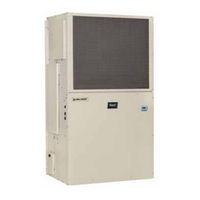
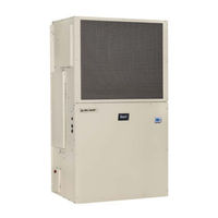
Wall-Mount Air Conditioner
Brand: Bard
|
Category: Air Conditioner
|
Size: 6 MB
Table of Contents
-
Overview5
-
Cooling Mode20
-
Heating Mode20
-
Cooling Mode21
-
Quick Menu32
-
Setpoints32
-
Information32
-
Alarm Log34
-
Operation36
-
Unit On/Off36
-
Orphan Mode37
-
Zone37
-
Staging39
-
Blower44
-
Filters46
-
Compressor51
-
Test Mode52
-
Economizer54
-
Actuator54
-
Dust Sensor55
-
Damper Blade56
-
General66
-
General85
-
Leak Test86
-
Evacuation86
-
Charging87
-
Controller106
-
Optional Sensors106
-
General107
-
Shipping Damage107
-
Site Preparation109
-
Figure 1109
-
Figure 3113
-
Figure 5114
-
Figure 18122
-
Figure 19124
-
Figure 20125
-
Figure 21126
-
Sensor127
-
Figure 22127
-
Figure 23128
-
Figure 28132
-
Figure 30134
-
Figure 31135
-
Supply Wiring136
-
Figure 32136
-
Figure 34138
-
System Set up139
-
Figure 36139
-
Figure 37140
-
Figure 38141
-
Figure 41142
-
Figure 44143
-
Figure 48144
-
Figure 51145
Advertisement
Bard FUSION-TEC WR58BPA Service Instructions Manual (54 pages)
WALL-MOUNT AIR CONDITIONER
Brand: Bard
|
Category: Air Conditioner
|
Size: 1 MB
Table of Contents
-
-
-
-
Operation
12-
Unit On/Off12
-
Orphan Model13
-
-
Staging15
-
Zone13
-
-
-
-
Output Volts
20 -
Table 8
21-
Heating20
-
Mode20
-
Wr36Bp* 120021
-
Wr58Bp21
-
Filters22
-
-
Compressor26
-
Economizer29
-
Actuator29
-
Dust Sensor30
-
Damper Blade31
-
-
-
-
General40
-
Maintenance
42 -
Bard FUSION-TEC WR58BPA Service Instructions Manual (56 pages)
Wall-Mount
Brand: Bard
|
Category: Air Conditioner
|
Size: 2 MB
Table of Contents
-
-
-
-
Alarm Log10
-
-
Operation
12-
Unit On/Off12
-
Orphan Model13
-
-
-
Staging15
-
Zone13
-
-
-
-
-
-
Compressor27
-
-
Test Mode28
-
-
Economizer30
-
-
Actuator30
-
Dust Sensor31
-
Damper Blade32
-
-
-
General42
-
-
Maintenance
44 -
Advertisement
Advertisement