Sign In
Upload
Manuals
Brands
Balluff Manuals
Transducer
BTL7-V50D-M0500-P-C003
Balluff BTL7-V50D-M0500-P-C003 Manuals
Manuals and User Guides for Balluff BTL7-V50D-M0500-P-C003. We have
1
Balluff BTL7-V50D-M0500-P-C003 manual available for free PDF download: User Manual
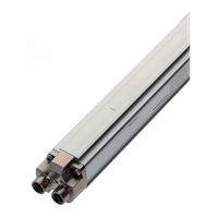
Balluff BTL7-V50D-M0500-P-C003 User Manual (95 pages)
Transducer in a Profile Housing
Brand:
Balluff
| Category:
Transducer
| Size: 6.36 MB
Table of Contents
Deutsch
3
Table of Contents
3
Zulassungen und Kennzeichnungen
4
Verwendete Symbole und Konventionen
4
Lieferumfang
4
Sicherheit
5
Bestimmungsgemäße Verwendung
5
Allgemeines zur Sicherheit des Wegmesssystems
5
Bedeutung der Warnhinweise
5
Entsorgung
5
Aufbau und Funktion
6
Aufbau
6
Funktion
6
LED Anzeige
7
LED 1: BTL-Status
7
LED 2: Netzwerkstatus (Duo-LED)
7
LED 3 / LED 4: Link/Activity
7
Geführte Positionsgeber
8
Wegaufnehmer Einbauen
8
Einbau und Anschluss
8
Freie Positionsgeber
9
Schirmung und Kabelverlegung
10
Elektrischer Anschluss
10
Steckverbinder BTL7
10
Inbetriebnahme
11
System in Betrieb Nehmen
11
Hinweise zum Betrieb
11
Technische Daten
12
Umgebungsbedingungen
12
Spannungsversorgung (Extern)
12
Ausgang
12
Maße, Gewichte
12
Maximale Abtastfrequenz F
12
Genauigkeit
12
Zubehör
13
Geführte Positionsgeber Gelenkstange BTL2-GS10
13
Freie Positionsgeber
14
Datenkabel, Konfektioniert mit M12-Stecker
15
Datenkabel, Konfektioniert mit RJ45-Stecker
15
Versorgungskabel, Konfektioniert mit Gewinkeltem M8-Stecker
15
Versorgungskabel, Konfektioniert mit Geradem M8-Stecker
15
Steckverbinder
15
Datenstecker Gerade, Frei Konfektionierbar
16
Datenstecker Gewinkelt, Frei Konfektionierbar
16
Typenschlüssel
17
Anhang
18
Umrechnung Längeneinheiten
18
Typenschild
18
English
22
Approvals and Markings
23
Notes to the User
23
Scope of Delivery
23
Symbols and Conventions
23
Disposal
24
Explanation of the Warnings
24
General Safety Notes for the Position Measuring System
24
Intended Use
24
Construction and Function
25
Function
25
LED 1: BTL Status
26
LED 3 / LED 4: Link/Activity
26
Captive Magnets
27
Installation and Connection
27
Installing the Transducer
27
Floating Magnets
28
Connector BTL7
29
Electrical Connection
29
Shielding and Cable Routing
29
Operating Notes
30
Starting up the System
30
Startup
30
Ambient Conditions
31
Dimensions, Weights
31
Maximum Sampling Rate F
31
Output
31
Supply Voltage (External)
31
Technical Data
31
Btl2-Gs10
32
Captive Magnets
32
Connectors
34
Data Cable, Preassembled with M12 Plug
34
Data Cable, Preassembled with RJ45 Plug
34
Advertisement
Advertisement
Related Products
Balluff BTL7-V50D-M P-C003 Series
Balluff BTL7-V50D-M1500-B-SA211-C003
Balluff BTL7-V50D-M0100-B-C003
Balluff BTL7-V50D-M0060-P-C003
Balluff BTL7-V50E-M P-C003 Series
Balluff BTL7-V50T-M P-C003 Series
Balluff BTL7-V50T-M0500-P-C003
Balluff BTL7-V50T-M-P-C003 Series
Balluff BTL7-E512 Series
Balluff BTL7-A501 Series
Balluff Categories
Accessories
Transducer
Industrial Equipment
Switch
Rfid Systems
More Balluff Manuals
Login
Sign In
OR
Sign in with Facebook
Sign in with Google
Upload manual
Upload from disk
Upload from URL