Sign In
Upload
Manuals
Brands
Balluff Manuals
Control Unit
BNI PNT-508-105-Z031
Balluff BNI PNT-508-105-Z031 Manuals
Manuals and User Guides for Balluff BNI PNT-508-105-Z031. We have
1
Balluff BNI PNT-508-105-Z031 manual available for free PDF download: User Manual
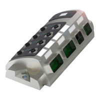
Balluff BNI PNT-508-105-Z031 User Manual (45 pages)
IP67 Module
Brand:
Balluff
| Category:
Control Unit
| Size: 2.76 MB
Table of Contents
Table of Contents
2
Inputs Pin
3
Outputs Pin
3
Actuator Warning Pin 4 / Pin
3
Restart Pin 4 / Pin
3
1 General
5
About this Manual
5
Structure of the Manual
5
Typographical Conventions
5
Enumerations
5
Actions
5
Syntax
5
Cross-References
5
Symbols
5
Abbreviations
5
2 Safety
6
Proper Use
6
Installation and Startup
6
General Safety Instructions
6
Resistance to Aggressive Substances
6
Hazardous Voltage
6
3 Getting Started
7
Module Overview
7
Mechanical Connection
8
Electrical Connection
8
Power Supply
8
Grounding
8
PROFINET Interface BNI PNT-508-105-Z031And BNI PNT-508-105-Z031-004
9
PROFINET Interface BNI PNT-508-105-Z031-002 and BNI PNT-508-105-Z031-004
9
I/O Port
10
IO-Link Port
10
Port
10
4 Technical Data
11
Dimensions BNI PNT-508-105-Z031
11
Mechanical Data
11
Operating Conditions
11
Electrical Data
11
Profinet
11
Dimensions BNI PNT-508-105-Z031-002
12
Mechanical Data
12
Operating Conditions
12
Electrical Data
12
Profinet
12
Dimensions BNI PNT-508-105-Z031-004
13
Mechanical Data
13
Operating Conditions
13
Electrical Data
13
Profinet
13
Function Indicators
14
Module Status
14
Port
14
5 Integration
15
Configuration
15
GSDML File
15
Integration of the Module
15
Configuration of the Header Module
16
Hardware Configuration
17
IO-Link Configuration
18
Device Name, Profinet Address
19
Establishing Device Relationship
20
Assigning Device Name
20
Concluding the Configuration
21
Functions in Module Properties
22
Module Settings
22
Port Functions
22
Safe State
22
Bit Mapping and Function
23
IO-Link Modules
23
Switching IO-Link Diagnostics on / off
24
IO-Link Communication
24
Peripheral Error, Socket
24
Short Circuit
24
Sensor Supply
24
Station Diagnostics
24
Display LED
24
IO-Link Functions
25
Cycle Settings
25
Data Selection
25
Validation
25
Parameter Server
26
6 Display
27
General
27
Controls and Visualization
27
Display Information
27
Design and Symbols
28
Startup
28
Main Menu
28
Factory Reset
29
Module Info
29
7 Webserver
30
General
30
Home
31
Diagnostics Procedure
32
Device Properties
33
Diagnostics Module
35
Configurations
36
Contact
36
8 Diagnostics
37
Diagnostics Message
37
Block Header
38
Block Type
38
Block Length
38
Block Version High
38
Block Version Low
38
Alarm Type
38
Api
38
Slot
38
Subslot
38
Module ID
38
Alarmspecifier
39
Sequence Number
39
Channel Diagnostic
39
Manufacturer-Specific Diagnosis
39
Submodules
39
Diagnostic State
39
Ardiagnosis State
39
User Structure ID
39
Channel Number
40
Channel Properties
41
Type
41
Accumulative
41
Maintenance
41
Specifier
41
Direction
41
Channel Error Type
42
9 Configuration of IO-Link Devices
43
General
43
Function Block
43
Reading
43
Writing
43
10 Appendix
44
Included in the Scope of Delivery
44
Order Number
44
Order Information
44
Advertisement
Advertisement
Related Products
Balluff BNI PNT-508-005-E002
Balluff BNI PNT-508-105-Z031-002
Balluff BNI PNT-508-105-Z031-004
Balluff BNI PBS-206-000-Z001
Balluff BNI PBS-202-000-Z001
Balluff BNI PBS-506-001-Z011
Balluff BNI PBS-507-001-Z011
Balluff BNI PNT-502-102-Z015
Balluff BNI ECT-507-005-Z040
Balluff BNI ECT-527-005-Z040
Balluff Categories
Accessories
Transducer
Industrial Equipment
Switch
Rfid Systems
More Balluff Manuals
Login
Sign In
OR
Sign in with Facebook
Sign in with Google
Upload manual
Upload from disk
Upload from URL