Sign In
Upload
Manuals
Brands
Baker Manuals
Laboratory Equipment
InvivO2 1000
User Manuals: Baker InvivO2 1000 Culture Workstations
Manuals and User Guides for Baker InvivO2 1000 Culture Workstations. We have
1
Baker InvivO2 1000 Culture Workstations manual available for free PDF download: User Manual
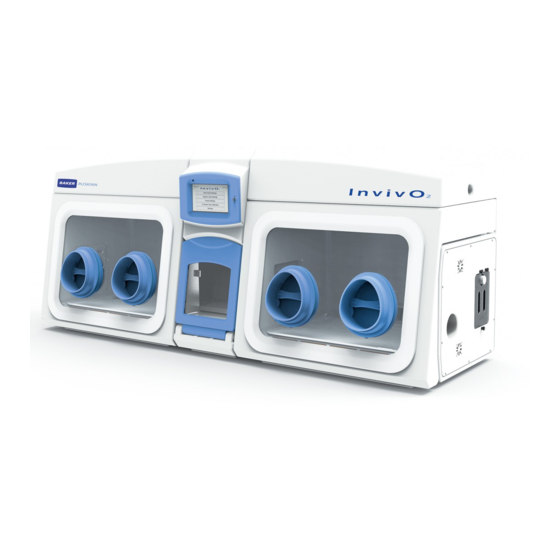
Baker InvivO2 1000 User Manual (67 pages)
Dual Chamber Hypoxia Workstation
Brand:
Baker
| Category:
Laboratory Equipment
| Size: 3 MB
Table of Contents
Table of Contents
2
Table of Figures
4
Introduction
7
Safety Instructions
8
Regulatory Compliance
9
European Region
9
North American Region
10
Precautions
10
Symbols
11
Table 1: List of Symbols
11
Transport and Storage
12
Location and Handling of the Invivo2 Workstation
12
Environmental Operating Conditions
12
Service Requirements
13
Electrical Supply Requirements
13
Figure 1: Rear Connections
13
Table 2: Electrical Service Requirements
13
Table 3: Fuse Ratings
13
Gas Supply Requirements
14
Figure 2: Gas Connection Graphic
14
Table 4: Standard Gases
14
Table 5: Additional Gases for Specific Operating Modes
14
Invivo2 1000 Dual Workstation Overview
15
Front View
15
Dual Workstation
15
Front Interior Views
16
Figure 4: Invivo Internal View from Left
16
Figure 5: Invivo Internal View from Right
16
Left Side View
17
Figure 6: Left Side End Panel with Ultrasonic Humidity Option
17
Rear View
18
Figure 7: Rear End Panel and Supply Connections
18
Figure 8: Gas and Electrical Connections
18
Using the Workstation
19
Using the Interlock
19
Interlock Overview
19
Operating the Interlock Outer Door
19
Icon 1: Interlock Outer Door
19
Operating the Interlock Inner Doors
20
Transferring Material into the Workstation Chamber Via the Interlock
20
Screen 1: Interlock Purge
21
Screen 2: Interlock Purge Timer
21
Removing Material from the Workstation Chamber Via the Interlock
22
Hand Access to the Main Chamber
23
Figure 9: Ezee -Sleeves
23
Vacuum Operation
24
Figure 10: Compressed Ezee-Sleeve for Entry
24
Figure 11: Arm Inserted into Ezee-Sleeve (Shown with and Without Ezee-Sleeve)
24
Figure 12: Foot Pedals for Right and Left Glove Ports
25
Figure 13: Ezee-Sleeve before Vacuum
25
Figure 14: Ezee-Sleeve after Vacuum
25
Workstation Entry
26
Figure 15: Glove Port Cap
26
Figure 16: Glove Port Cap Stowage and Locator
26
Figure 17: Glove Port Cap Storage Location Inside Workstation
27
Workstation Exit
28
Figure 18: Glove Port Cap
28
Figure 19: Glove Port Locator
28
Humidity Control
29
Figure 20: Aquasorb Sachets - Empty and Charged
29
Figure 21: Aquasorb Sachet in Workstation
29
Figure 22: Humidity System Water Tank
30
Icon 2: Humidity Low Alarm
30
Figure 23: Water Tank Thumb Screw
31
Figure 24: Water Tank Lowered for Removal
31
Figure 25: Water Tank Tilted Forward Partially Removed
32
Figure 26: Water Tank Top Tube Removal
32
Figure 27: Water Tank Electrical Connector
33
Figure 28: Water Tank Bottom Lifted out
33
Figure 29: Water Tank Bottom Tube Disconnection
34
Figure 30: Condensate Plate
35
Figure 31: Condensate Output and Tray
35
Screens
36
Main Screen
36
Screen 3: Workstation Selection
36
Left and Right Workstation Main Menus
37
Screen 4: Left Main Menu
37
Screen 5: Right Main Menu
37
Invivo 2 Initial Settings Screen
38
Screen 7: Oxygen Level Set-Point Pop-Up
38
Initial Settings Screen with Ultrasonic Humidity Option
38
Table 6: Settings Screen Column Functions
38
Screen 8: Initial Settings Screen with Aquasorb Humidity
39
Environment Control
40
Screen 9: Environment Control Overview
40
Screen 10: Exit Gas Control Warning
40
Workstation Overview
41
Screen 11: Workstation Overview
41
Screen 12: Workstation Not in Use
41
Icon 3: Workstation Overview
41
Workstation Switching
42
Workstation Environment Control Screens Overview
42
Figure 32: Workstation Environment Control Screens Overview
42
Data Logs
43
Screen 13: Trend Log
43
Utilities
44
Screen 14: Utilities Menu
44
Icon 4: Internal Lights Control
44
Hypoxic Cycle
45
Screen 15: Hypoxic Cycle Menu - Continuous Cycle on
45
Screen 16: Hypoxic Cycle Menu - Continuous Cycle off
46
Screen 17: Hypoxic Cycle Temperature and Humidity Settings
47
Oxygen Sensor Calibration
48
Screen 18: Oxygen Sensor Calibration
48
Help / Settings
49
Screen 19: Help / Settings Menu
49
Warnings
50
Screen 20: Temperature Alarm Screen
50
Screen 21: Water Tank Low Warning Screen
51
Screen 22: USB Memory Warning Screen
52
Screen 23: Gas MIX Time Limit Warning Screen
53
Screen 24: Input Gas Pressure Alarm
54
Table 7: Audible Alarm Sounds
54
Usb Trend Log
55
Table 8: Trend Log Data Fields
55
Cleaning and Service Requirements
56
Service and Cleaning Overview
56
Table 9: Cleaning and Service Details
56
Cleaning Procedure - During and after each Use
57
Cleaning Procedure - Deep Clean with Front Screens Removed
58
Figure 33: Front Screen Pneumatic Connector Disconnection
58
Icon 5: Front Screen Release
58
Year Service
61
Figure 34: Ceiling Panel Thumb Screws
61
Figure 35: Ceiling Panel Handle and Grab Catch
61
Figure 36: Large Detox Sachet
62
Figure 37: Gloveport Sleeves
62
Troubleshooting
63
The Workstation will Not Switch on
63
The Circuit Breaker Trips
63
Low Gas Pressure
63
Excessive Gas Usage
64
Internal Equipment Not Powering up
64
The Workstation Is Only Partially Operational
64
Warranty Information
65
Disposal Information
66
Contact Details
67
Advertisement
Advertisement
Related Products
Baker Invivo2 300 UM-010
Baker Invivo2 UM-014
Baker InvivO2 400
Baker InvivO2 500
Baker Druck ics IDT 600
Baker BD InoqulA
Baker BDINQ400
Baker Bugbox Ax
Baker ChemGARD FH4
Baker ChemGARD FH5
Baker Categories
Laboratory Equipment
Measuring Instruments
Industrial Equipment
Desktop
Saw
More Baker Manuals
Login
Sign In
OR
Sign in with Facebook
Sign in with Google
Upload manual
Upload from disk
Upload from URL