Sign In
Upload
Manuals
Brands
Baker Hughes Manuals
Measuring Instruments
Panametrics AquaTrans AT600
Baker Hughes Panametrics AquaTrans AT600 Manuals
Manuals and User Guides for Baker Hughes Panametrics AquaTrans AT600. We have
1
Baker Hughes Panametrics AquaTrans AT600 manual available for free PDF download: User Manual
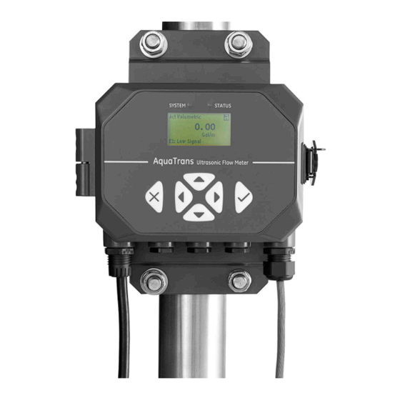
Baker Hughes Panametrics AquaTrans AT600 User Manual (174 pages)
Ultrasonic flow meter for liquids
Brand:
Baker Hughes
| Category:
Measuring Instruments
| Size: 7 MB
Table of Contents
Table of Contents
7
Chapter 1. General Installation Instructions
11
Introduction
11
Cf-Lp
11
Theory of Operation
12
C-Rs
12
C-Pt
12
Safety Guidelines
13
Unpacking the AT600 System
14
Installing the Electronics Enclosure
15
Calculating the Transducer Spacing
16
Choosing a Clamp-On Fixture/Transducer Location
17
Mounting the Clamp-On Fixture and Transducer System
18
Transducer Frequency
19
Chapter 2. Clamp-On Fixture and Transducer Installation
21
Installing an AT600 Clamp-On Fixture and Transducer System
21
Transducer Spacing = 32 to 250 MM or 50 to 320 MM, Traverses = 2, Fixtures = 1
21
Transducer Spacing = 320 to 940 MM, Traverses = 2, Fixtures = 2
23
Transducer Spacing = 0 to 250 MM or 0 to 320 MM, Traverses = 1, Fixtures = 2
24
Transducer Spacing >320 MM, Traverses = 1, Fixtures = 2
26
Installing a CF-ES Clamp-On Fixture and Transducer System
26
Go Directly To: "Installing a CF-ES Clamp-On Fixture and Transducer System
26
Installing a General Clamping Fixture and Transducer System
27
Installing C-RS or C-PT Transducers with an RG316 Cable
27
Installing C-RS or C-PT Transducers with an RG62 Cable
27
Go Directly To: "Installing a General Clamping Fixture and Transducer System
27
Chapter 3. Wiring the AT600 Electronics
29
Wiring Diagram
29
Wiring the Line Power
31
Wiring the Transducers
33
Wiring the System Ground
33
Wiring the Analog Output for HART Communication
34
Wiring the Modbus Communication
34
Wiring the Frequency/Totalizer/ Alarm Output
35
Wiring the Gate Input
35
Chapter 4. Initial Setup and Programming
37
Introduction
37
AT600 Keypad Operation
38
Display Programming
39
Changing the Display for One- or Two Variable Screens
40
Changing the Measurement Type for One or Two-Variable Screens
41
Changing the Measurement Type or Units for the Totalizer Screens
41
Starting or Stopping the Totalizer Measurement
43
Resetting the Totalizer
44
Entering the Main Menu
44
Display Format
45
Keypad Lockout
45
Language
46
Program and Program Review Menus
46
Program Review
47
Program
47
User Preferences
47
Setting
47
Units Setting
48
Density
49
Password
49
Display
50
Backlight
50
Timeout
50
Inputs/Outputs
51
Programming the Analog Output Menu
51
Setting the Analog Measurements
52
Setting the Base Value and the Full Value
52
Calibrate the Output
53
Setting Error Handling
53
Programming the Digital Output Menu
54
Disable the Digital Output
54
Setting the Pulse Output
55
Setting the Frequency
57
Setting the Alarm
60
Programming the Modbus/Service Port
62
Programming Digital Communications
63
Modbus
63
Hart
65
Sensor Setup
66
Meter Setup
66
Setting the Zero Cutoff
66
Mounting Type
67
Setting the Mounting Type
67
Programming the Pipe Menu When Wetted Selected
68
Setting the Pipe OD, ID, and Wall Thickness
68
Programming the Pipe Menu When Clamp-On Selected
69
Setting the Pipe OD, ID, and Wall Thickness
69
Selecting the Pipe Material
69
Setting the Pipe Lining
71
Programming the Transducer When Clamp-On Selected
72
Entering a Standard Transducer
72
Entering a Special Transducer
74
Programming the Transducer When Wetted Selected
77
Entering a Standard Transducer
77
Entering a Special Transducer
78
Programming the Number of Traverses
79
Programming the Fluid Type
80
Programming the Fluid Temperature
81
Calculating the Path When Clampon Selected
82
Enter the Path When Wetted Selected
83
Chapter 5. Error Codes and Troubleshooting
85
Error Display in the User Interface
85
Error Header
85
Flow Error String
85
E1: Low Signal
86
E2: Sound Speed Error
86
E3: Velocity Range
86
E4: Signal Quality
86
E5: Amplitude Error
86
E6: Cycle Skip
87
Diagnostics
87
Introduction
87
Flowcell Problems
87
Fluid Problems
87
Pipe Problems
88
Chapter 6. Communication
89
Modbus
89
Introduction
89
MODBUS Register Map
89
Hart
96
Device Identification
96
Commands
96
Universal Commands
96
Common Commands
97
Device Specific Commands
97
Additional Device Status
145
Device Variables
146
HART Engineering Units
147
Appendix A. Specifications
151
Overall Operation and Performance
151
Electronics
152
Clamp-On Ultrasonic Flow Transducers
153
General
154
Wiring Cable Specifications and Requirements
154
A.4.2 Cable Fixing Requirement and Gland Torque
154
Display Languages
154
A.4.4 Product Models
154
Appendix B. Specifications
155
Service Record
155
Data Entry
155
Initial Settings
156
Diagnostic Parameters
157
Appendix C. Specifications
159
Introduction
159
System Requirements
159
Preparation
159
Performing the Firmware Update
159
Check the Current Firmware Version
159
C.2.2 Update Steps
160
Clearing an S2 Warning
161
Support
161
Appendix D. Menu Maps
163
The Display Measurement Menu
163
The Main Menu
164
The Main Menu > User Preferences Menu
165
The Main Menu > Inputs/Outputs Menu
166
The Main Menu > Sensor Setup Menu
167
The Main Menu > Calibration Menu
168
The Main Menu > Advanced Menu
169
The Main Menu > Factory Menu
170
Advertisement
Advertisement
Related Products
Baker Hughes Druck ADROIT6000
Baker Hughes Druck ADTS405
Baker Hughes Druck ADTS403
Baker Hughes Druck ADTS542F
Baker Hughes Druck ADTS552F
Baker Hughes Druck ADTS553F
Baker Hughes Druck ADTS554F
Baker Hughes Druck ADTS405MK2
Baker Hughes 022-508-909
Baker Hughes Bently Nevada Ranger Pro
Baker Hughes Categories
Control Unit
Measuring Instruments
Valve Positioners
Test Equipment
Controller
More Baker Hughes Manuals
Login
Sign In
OR
Sign in with Facebook
Sign in with Google
Upload manual
Upload from disk
Upload from URL