Sign In
Upload
Manuals
Brands
Badger Meter Manuals
Measuring Instruments
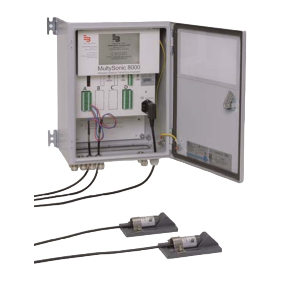
MultySonic 8000
Badger Meter MultySonic 8000 Manuals
Manuals and User Guides for Badger Meter MultySonic 8000. We have
1
Badger Meter MultySonic 8000 manual available for free PDF download: Instruction Manual
Badger Meter MultySonic 8000 Instruction Manual (87 pages)
Brand:
Badger Meter
| Category:
Measuring Instruments
| Size: 2 MB
Table of Contents
Table of Contents
2
Description
6
Measurement Principle
6
Applicable Standards
6
Measurement Accuracy
6
Specialised Applications
6
Specifications
7
Sensors
7
Evaluation Unit
7
Acoustic Path
7
Analogue Inputs for Water Level Sensors
7
Display with Touch Screen
7
Analogue Outputs
8
Cable for Ultrasonic Transducers
8
Safety Standards and EMC Guidelines
9
Interface Specifications
9
Analogue Inputs
9
Analogue Outputs
9
Relay Outputs
10
Pulse Outputs
10
LAN Interface (Ethernet)
10
USB Interface
10
RS232 Interface
10
Flow Calculation
11
Calculation Algorithms
11
In "Partially Filled/Filled Conduits, Open Channel" Mode
11
Crossing Paths
15
In "Full Conduit" Mode
15
Water Level Measurement
15
Installation of the Electronic Unit
16
Electrical Connection
16
Power Supply (AC)
16
Ultrasonic Board
17
Connecting the Ultrasonic Transducers
18
Connection in Explosive Areas
19
I/O Board
19
Connection of Water Level Measuring Devices to the Analogue Inputs
21
Connection to the Analogue Outputs
21
Connection to the Digital Outputs
22
Using Several I/O Boards
22
Access to Multysonic 8000 Via Ethernet
22
Use of USB Memory Sticks
22
Transferring a New Parameter File
23
Activating a Transferred Parameter File
23
Downloading an Active Parameter File from Multysonic 8000 to
23
USB Memory Stick
23
Reading out the Data Logger
24
Performing Updates and Upgrades
24
Installation and Removal of Electronic Boards / Reconfiguration of Boards
24
Programming and Operation
29
Operation
29
The Sections Menu
29
Section Status
29
Section Alarm
30
The Input/Output Menu
30
The Scan Menu
30
The Paths Menu
30
The Maintenance Menu
32
Activating of Parameter Files
32
Reset
32
Switch off of Multysonic 8000
32
Menu Customisation
33
Using the LAN Interface
33
Using the USB Interface
33
User-Defined Settings
34
General Information on Software Use
34
Creating a New Parameter File
34
Loading a New Parameter File
34
Language Selection
34
System Configuration
34
Definition of Existing Hardware
34
Number of Sections
35
Flow Meter ID
35
Section Configuration
35
Section Selection
38
Activation of Individual Acoustic Paths to a Section
38
Geometric Definition of Your Measuring Site (Drain)
38
Not Activated
38
Open Channel
38
Partially Filled And/Or Filled Pipe Compound
38
Filled Pipe/Filled Compound
39
Round
39
Square
39
Round with Spline Interpolation
39
Define Sampling Points" Sampling Point Editor
40
Path Configuration
41
The Expert Menu
43
Auto Window
44
Sensor Delay
44
Send Sequence
44
Frequency
44
Adc
44
Frequency Filter Low
44
Frequency Filter High
44
Automatic Gain Control (AGC)
45
Signal Min
45
Signal Max
45
Manual Gain
45
Maximum Gain
45
Correlation Quality
46
Cal Factor
46
PATH XX Samples
46
Activate Cut off
46
Cutoff Trigger
46
Samples before Cut off
47
Samples after Cut off
47
Cutoff Filter
47
Level Measurement Configuration
47
Analogue Ouput Configuration
48
Digital Output Configuration
49
Counter Pulses
49
Section Alarm
50
Constant Values
50
Min-Alarm, Max-Alarm, Min-Max Alarms
50
Example 1: Setting Min-Alarm for Level
50
Example 2: Setting Min-Max-Alarm for Flow
51
Min / Max Frequency
51
Basic Settings Configuration
51
Medium Configuration
52
Basic Parameter Configuration
54
Minimal Sensor Surcharge
54
Low Flow Cut off
54
Low Level Cut off
54
Temperature Offset
55
Damping
55
Max. Level
55
Path Substitution
55
Minimum Number of Functioning Paths
56
Dry Weather Flow Configuration
56
Using Manning-Strickler's Equation
56
Using Individual Discharge Curve
57
Signal Plausibility
58
Min. and Max. Velocity
59
Min. Signal Quality
59
Min. and Max. Flow Speed
59
Creating the Parameter File
60
Appendix
61
Connection Plans for the Pulse Outputs
61
Weighting of the Paths with Filled Cross-Sections in Accordance with
62
Iso60041 (Iec41)
62
Weighting of the Paths for Filled Round Cross-Sections
62
(Gauss-Jacobi Method)
62
Weighting of the Paths for Filled, Rectangular Cross-Sections
63
(Gauss-Legendre Method)
63
Exerpt IEC41 - Calculation of Flow with Weighing Factors
64
Access to Multysonic 8000 Via Ethernet (LAN)
67
Using Ethernet Cable Connection
67
Access Via Http Protocol - Multysonic 8000 Integrated Webserver
67
Access Via Ftp-Server
68
Downloading Data Logger Files
69
Downloading / Uploading of Parameter Files
70
Activating Parameter Files Via Http
71
Multysonic 8000 Network Configuration
71
General
71
Donwloading the File Inittab
71
Adjust the File Inittab
73
Change the IP Address
73
Change the Default Gateway
73
Change Subnet Mask
74
Transferring File Inittab Back to Multysonic 8000
74
Troubleshooting
74
Parametering of the RS232 Interface
75
General
75
Data Which Can be Transferred Via RS232
75
RS232 Fixed Settings
75
ASCII Output String
75
Communication.par - Structure (1)
76
Uploading Parameter File Communication.par to Multysonic 8000
80
Downloading Parameter File Communication.par from Multysonic 8000
81
Downloading Data Files
81
Multysonic 8000 Display (Touchscreen) - Structure
82
Handling of Data Logger Files
83
Structure of Data Logger Files
83
Unpack Data Logger Files
84
Handling of Additional Data Logger Files
85
Advertisement
Advertisement
Related Products
Badger Meter 1000
Badger Meter 10000
Badger Meter 160
Badger Meter 2000
Badger Meter 2100
Badger Meter 2100R+
Badger Meter 3500
Badger Meter 380 Series
Badger Meter 380CS
Badger Meter 380HS
Badger Meter Categories
Measuring Instruments
Transmitter
Controller
Accessories
Monitor
More Badger Meter Manuals
Login
Sign In
OR
Sign in with Facebook
Sign in with Google
Upload manual
Upload from disk
Upload from URL