Sign In
Upload
Manuals
Brands
Bacharach Manuals
Microphone
MultiZone CO2-MZ
Bacharach MultiZone CO2-MZ Manuals
Manuals and User Guides for Bacharach MultiZone CO2-MZ. We have
2
Bacharach MultiZone CO2-MZ manuals available for free PDF download: Installation & Operation Manual, Instruction
Bacharach MultiZone CO2-MZ Installation & Operation Manual (84 pages)
Halogen, Ammonia, Carbon Dioxide Multi-Zone Gas Monitors
Brand:
Bacharach
| Category:
Microphone
| Size: 5 MB
Table of Contents
Table of Contents
3
Section 1. Introduction
7
About this Manual
7
Warnings and Cautions
7
Safety Precautions
7
Hazardous Areas
7
Combustible and Flammable Gases
8
AC Power Supply
8
Protective Grounding
8
Explosive Atmosphere
8
Proper Exhaust Venting
8
Accessing the Interior of the Monitor
8
Altitude Limit
8
Misuse and Modifications to the Instrument
9
In Case of Malfunction
9
Fusing
9
Installation Category
9
Cleaning
9
Key External Hardware Components
9
Functional Overview
9
General Description
9
Communications Options
10
Understanding Monitoring Levels
10
Response to the Presence of Multiple Refrigerants (HGM Only)
10
Suggested Location of Sampling Points
10
Locating a Remote Display (Optional)
11
Specifications
12
Section 2. Installation
14
Installation Considerations
14
Warnings and Cautions
14
Inspection
14
Location of the Monitor
14
Mounting Instructions
14
Overview
15
Connecting Gas Sample Lines
16
Tubing Considerations
16
Connecting P Urge Line
17
Connecting Exhaust Line
17
Connecting Sample Intake Lines
17
Installing an Optional Splitter Kit
18
Connecting the Water Trap
18
Interior Components
19
Electrical Wiring
19
Connecting Communications Devices
21
Remote Display Module (RD) Connection
21
Integrating with Building Management Systems
21
Larger Integrated Systems
21
Changing Terminator Switch Settings
22
Personal Computer
22
Terminating Multiple Monitors
23
Connecting to a Building Management System
23
PC Software
24
Operation
24
Saving and Sending Programs
26
Trend Data
26
Converting the TREND Text File to a Microsoft Excel File
26
Saving and Printing Screens and Logs
26
USB Type Laptops
26
1000 M Ulti-Zone Gas M Onitors
26
Optional Current Loop Interfaces
27
Optional 4-20 Ma DC Outputs
27
Ma DC Connections
28
Connecting External Alarms
29
Overview
29
Connection
29
Section 3. Setup Programming
31
Initial Power up
31
Data Display Screen
31
Navigating to the 1St Setup Screen
31
Navigating to the 2Nd Setup Screen
31
Location
32
Number of Zones Installed
32
Alarm Acknowledge Mode
32
Audible Alarm
32
Zone Hold
33
Detection Limit
33
Loop Mode
33
Loop2 Factor
33
Re-Zero Mode
34
Navigating to the 3Rd Setup Screen
34
Overview
34
Baud Rate
34
Node Address
34
Password
34
Additional Service Features
35
Service Timeout
35
DET Digipot
35
Node Address
36
Sensor Temperature Coefficient (for Factory Use Only)
36
Password
36
Acquiring Temperature Coefficient (for Factory Use Only)
36
IR Digipot
36
Establishing the CO Sensor Baseline
36
Section 4. General Operation
37
Functional Overview
37
The Zone Setup Screen
37
Location
37
Gas/Refrigerant Type
37
Distance
38
Zone Temperat Ure
38
Current Detection Reading
38
Log Interval
38
Navigating to the 2Nd Zone Setup Screen
38
Leak Level
39
Spill Level
39
Evacuation Level
39
Re-Setting the Peak PPM Value
39
Alarms
39
Functional Overview
39
Responding to Alarms
40
Alarm Detail Screen
40
Acknowledging Alarms
41
Silencing an Alarm
41
Clearing the Alarm Event Log
42
System Faults
42
Functional Overview
42
Navigating to the Fault Screen
43
Critical Faults
43
Non Critical Faults
44
Reset to Factory Default Settings
44
Clearing System Faults
44
Viewing Fault Log
45
Viewing Flow Log
45
The Trend Screen
46
Navigating to the Trend Screen
46
The Calibration Screen
46
Overview
46
Navigating to the Calibration Screen
47
Calibration Procedure (HGM and AGM Only)
47
Adjusting Calibration Factor (HGM and AGM Only)
47
CO 2 Atmospheric Concentration
48
Programming New Gases (HGM Only )
48
Zone Hold Mode
49
The Diagnostic Screen
50
Navigating to the Diagnostic Screen
50
Diagnostic Screen Overview
51
Section 5. Maintenance
53
Replacement Parts Overview
53
Replacement Parts and Optional Accessories
54
Troubleshooting
56
Appendix A. Recommended Refrigerant Gas Alarm Settings
59
Appendix B. Rs-485 Communications Protocol
61
Overview
61
MODBUS RTU Protocol
61
MZ MODBUS RTU Operation
61
Protocol Details
61
MZ Monitor Polling
62
Network Topologies
62
Key Comm Protocol Parameters
62
Summary of Registers
63
System Data Register 0X0010 (16 Dec) (R/W, 54 Bytes)
64
Status Register 0X001 (17 Dec) (R/W, 10 Bytes)
64
Fault Code Table
65
Zone Data Register 0X12Xx (R/W, 78 Bytes)
65
Alarms and Alarm Acknowledge
66
Date Time Register 0X0015 (21 Dec) (R/W, 14 Bytes)
66
Sensor Data Register 0X0016H (22 Dec) (R, 82 Bytes)
67
Release Zone Hold Register 0X0017H (23 Dec) (W, 10 Bytes)
67
Hold Zone Register 0X0018H (23 Dec) (W, 10 Bytes)
67
MZ Hold Mode
67
1000 M Ulti-Zone Gas M Onitors
68
Fault Log Register 0X1900-01 (6400-6401 Dec ) (R, 302 Bytes)
68
Flow Log Register 0X001F (31 Dec ) (R, 142 Bytes)
68
Alarm Log Register 0X1A 00-02 (6656-58 Dec) (R, 582 Bytes)
68
Service Mode Register 0X001B (27 Dec) (W, 10 Bytes)
69
Release Service Mode 0X001C (28 Dec) (W, 10 Bytes)
69
MZ Service Mode
69
PPM Register 0X001E (30 Dec) (R, 32 Bytes)
69
Zone Log Registers 0X3Xyy (R, 1502 Bytes)
69
MODB US Exception Responses
70
MODB US Gas Enumeration
70
Appendix C. System Menu Map
71
Appendix D. Agency Approvals
73
Appendix E. Service Centers
77
Index
79
Advertisement
Bacharach MultiZone CO2-MZ Instruction (82 pages)
MultiZone Gas Monitors
Brand:
Bacharach
| Category:
Measuring Instruments
| Size: 2 MB
Table of Contents
Table of Contents
4
Section 1. Introduction
8
Erxw 7Klv 0Dqxdo
8
Duqlqjv Dqg &Dxwlrqv
8
6Dihw\ 3Uhfdxwlrqv
8
D]Dugrxv $Uhdv
8
Rpexvwleoh Dqg )Odppdeoh *Dvhv
9
3Rzhu 6Xsso
9
3Urwhfwlyh *Urxqglqj
9
3Urshu
9
Ffhvvlqj Wkh ,Qwhulru Ri Wkh 0Rqlwru
9
0Lvxvh Dqg 0Rglilfdwlrqv Wr Wkh ,Qvwuxphqw
10
Q &Dvh Ri 0Doixqfwlrq
10
Xvlqj
10
Qvwdoodwlrq &Dwhjru
10
Owlwxgh /Lplw
10
Ohdqlqj
10
Xqfwlrqdo 2Yhuylhz
11
Hqhudo 'Hvfulswlrq
11
Rppxqlfdwlrqv 2Swlrqv
12
8Qghuvwdqglqj 0Rqlwrulqj /Hyhov
12
5Hvsrqvh Wr Wkh 3Uhvhqfh Ri 0Xowlsoh 5Hiuljhudqwv +*0 2Qo
12
6Xjjhvwhg /Rfdwlrq Ri 6Dpsolqj 3Rlqwv
12
Rfdwlqj D 5Hprwh 'Lvsod\ 2Swlrqdo
13
6Shflilfdwlrqv
14
Specifications
14
Section 2. Installation
16
2.1. Installation Considerations
16
Inspection
16
Rqqhfwlqj *DV 6Dpsoh /Lqhv
17
2Yhuylhz
17
7Xelqj &Rqvlghudwlrqv
18
Rqqhfwlqj 3Xujh /Lqh
18
Rqqhfwlqj
18
Rqqhfwlqj 6Dpsoh ,Qwdnh /Lqhv
18
Qvwdoolqj Dq 2Swlrqdo 6Solwwhu .Lw
19
Rqqhfwlqj Wkh :Dwhu 7Uds
19
Qwhulru &Rpsrqhqwv
20
Rqqhfwlqj &Rppxqlfdwlrqv 'Hylfhv
22
5Hprwh 'Lvsod\ 0Rgxoh 5' &Rqqhfwlrq
22
Qwhjudwlqj Zlwk %Xloglqj 0Dqdjhphqw 6\Vwhpv
22
Dujhu ,Qwhjudwhg 6\Vwhpv
22
Kdqjlqj 7Huplqdwru 6Zlwfk 6Hwwlqjv
23
3Huvrqdo &Rpsxwhu
23
7Huplqdwlqj 0Xowlsoh 0Rqlwruv
24
Rqqhfwlqj Wr D %Xloglqj 0Dqdjhphqw 6\Vwhp
24
3& 6Riwzduh
25
Operation
25
6Dylqj Dqg 6Hqglqj 3Urjudpv
27
7Uhqg 'Dwd
27
Rqyhuwlqj Wkh 75(1' 7H
27
6Dylqj Dqg 3Ulqwlqj 6Fuhhqv Dqg /Rjv
27
86% 7\Sh /Dswrsv
27
2Swlrqdo &Xuuhqw /Rrs ,Qwhuidfhv
28
Optional 4-20 P$ '& 2XWSXWV
28
P$ '& &Rqqhfwlrqv
29
Rqqhfwlqj
30
2Yhuylhz
30
2.10.2. Connection
30
Section 3. Setup Programming
32
3.1. Initial Power up
32
Dwd 'Lvsod\ 6Fuhhq
32
1Dyljdwlqj Wr Wkh Vw 6Hwxs 6Fuhhq
32
1DYLJDWLQJ WR WKH QG Setup Screen
32
Location
33
1Xpehu Ri =Rqhv ,Qvwdoohg
33
Odup $Fnqrzohgjh 0Rgh
33
Xgleoh $Odup
33
Rqh +Rog
34
Hwhfwlrq /Lplw
34
Loop Mode
34
Rrs )Dfwru
34
Zero Mode
35
1Dyljdwlqj Wr Wkh Ug 6Hwxs 6Fuhhq
35
2Yhuylhz
35
Dxg 5Dwh
35
Node Address
35
Password
35
Node Address
37
6Hqvru 7Hpshudwxuh &Rhiilflhqw )Ru )Dfwru\ 8Vh 2Qo
37
Password
37
Ftxlulqj 7Hpshudwxuh &Rhiilflhqw )Ru )Dfwru\ 8Vh 2Qo
37
'Ljlsrw
37
Sensor Baseline
37
Section 4. General Operation
38
XQFWLRQDO 2Yhuylhw
38
7Kh =Rqh 6Hwxs 6Fuhhq
38
Location
38
DV5Hiuljhudqw 7\Sh
38
Lvwdqfh
39
Rqh 7Hpshudwxuh
39
Xuuhqw 'Hwhfwlrq 5Hdglqj
39
Rj ,Qwhuydo
39
1Dyljdwlqj Wr Wkh Qg =Rqh 6Hwxs 6Fuhhq
39
Hdn /Hyho
40
6Sloo /Hyho
40
6Hwwlqj Wkh 3Hdn 330 9Doxh
40
Odupv
42
Section 5. Maintenance
54
Replacement Parts
55
Troubleshooting
57
Appendix B. Rs-485 Communications Protocol
62
Appendix C. System Menu Map
72
Appendix D. Agency Approvals
74
Index
77
Advertisement
Related Products
Bacharach CO2 Monitor 2800
Bacharach MultiZone
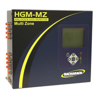
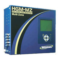
Bacharach MultiZone HGM-MZ
Bacharach MultiZone AGM-MZ
Bacharach FYRITE Gas Analyzer CO2 and O2 Indicators
Bacharach INJECTOR CALIBRATOR CD3
Bacharach CO2 Analyzer 3150
Bacharach Portable Combustion Analyzer
Bacharach Comfort Chek 400
Bacharach Comfort Chek 100
Bacharach Categories
Measuring Instruments
Test Equipment
Gas Detectors
Security Sensors
Controller
More Bacharach Manuals
Login
Sign In
OR
Sign in with Facebook
Sign in with Google
Upload manual
Upload from disk
Upload from URL