Sign In
Upload
Manuals
Brands
B&R Industries Manuals
Industrial PC
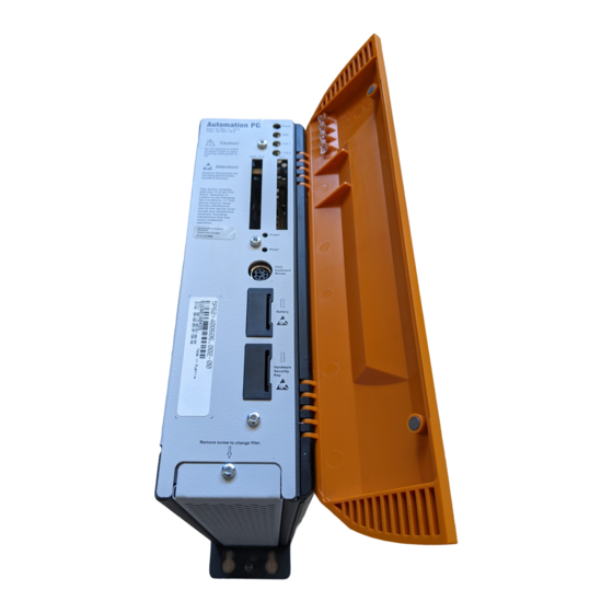
Automation PC 620
B&R Industries Automation PC 620 Manuals
Manuals and User Guides for B&R Industries Automation PC 620. We have
1
B&R Industries Automation PC 620 manual available for free PDF download: User Manual
B&R Industries Automation PC 620 User Manual (512 pages)
Brand:
B&R Industries
| Category:
Industrial PC
| Size: 36 MB
Table of Contents
Table of Contents
7
Chapter 1: General Information
17
Manual History
17
Safety Notices
21
Intended Use
21
Protection against Electrostatic Discharges
21
Packaging
21
Guidelines for Proper ESD Handling
21
Policy and Procedures
22
Transport and Storage
22
Mounting
23
Operation
23
Protection against Touching Electrical Parts
23
Programs, Viruses and Dangerous Programs
23
Organization of Safety Notices
24
Guidelines
24
Model Numbers
25
System Units
25
CPU Boards 815E
25
CPU Boards 855GME
26
Heat Sink
26
Main Memory
26
Drives
27
Interface Options
27
Fan Kit
28
AP Link Cards
28
Accessories
29
Batteries
29
Supply Voltage Connector
29
Compactflash Cards
29
USB Flash Drives
30
Cables
30
Other
31
Software
32
Chapter 2: Technical Data
33
Introduction
33
Features
34
System Components / Configuration
34
Selection Guide - Basic System
35
Selection Guide - Optional Components
36
Entire Device
38
APC620, 1 PCI Slot Variant
38
Interfaces
38
Technical Data
40
Dimensions
42
APC620, 2 PCI Slot Variant
43
Interfaces
43
Technical Data
45
Dimensions
47
APC620, 5 PCI Slot Variant
48
Interfaces
48
Technical Data
50
Dimensions
52
Environmental Temperatures for Systems with an 815E CPU Board
53
How Do You Determine the Maximum Environmental Temperature
55
Temperature Monitoring
55
Environmental Temperatures for Systems with an 855GME CPU Board
56
How Do You Determine the Maximum Environmental Temperature
58
Temperature Monitoring
58
Power Management for APC620 Systems with 1 and 2 PCI Slots
59
Power Consumption with System Unit 5PC600.SX01-00 1 PCI
60
Power Consumption with System Unit 5PC600.SX02-00 2 PCI
61
Power Consumption with System Unit 5PC600.SX02-01 2 PCI
62
Power Management, APC620 Systems with 5 PCI Slots
63
Power Consumption with System Unit 5PC600.SX05-00 5 PCI
64
Power Consumption with System Unit 5PC600.SX05-01 5 PCI
66
Humidity Specifications
67
General Device Interfaces
68
Serial Interfaces COM1
69
Serial Interfaces COM2
70
Ethernet Connection ETH1
71
Ethernet Connection ETH2
72
USB Port
73
VDC Supply Voltage
74
Monitor / Panel Connection
76
MIC, Line in and Line out Port
80
Add-On Interface Slot
81
AP Link Slot
81
PCI Slots
82
Status Leds
84
Compactflash Slot (CF1)
85
Hard Disk / Compactflash Slot (HDD/CF2)
86
Power Button
87
Reset Button
87
PS/2 Keyboard/Mouse
88
Battery
89
Hardware Security Key
90
Slide-In Slot 1 Drive Slot
91
Slide-In Slot 2 Drive Slot
92
Serial Number Sticker
93
Block Diagram
95
Entire Device with System Unit 5PC600.SX01-00
95
Entire Device with System Unit 5PC600.SX02-00
96
Entire Device with System Unit 5PC600.SX02-01
97
Entire Device with System Unit 5PC600.SX05-00
98
Entire Device with System Unit 5PC600.SX05-01
99
Individual Components
100
System Units
100
Technical Data
100
CPU Boards 815E
102
Technical Data
102
CPU Boards 855GME
104
Technical Data
104
Heat Sink
106
Main Memory
107
Technical Data
107
Drives
108
Add-On Hard Disk 30 GB 24X7 - 5AC600.HDDI-00
108
Add-On Hard Disk 20 GB ET - 5AC600.HDDI-01
111
Add-On Compactflash Slot - 5AC600.CFSI-00
114
Slide-In CD-ROM - 5AC600.CDXS-00
115
Slide-In DVD-ROM/CD-RW - 5AC600.DVDS-00
118
Slide-In DVD-R/RW, DVD+R/RW - 5AC600.DVRS-00
121
Slide-In CF 2 Slot - 5AC600.CFSS-00
126
Slide-In USB FDD - 5AC600.FDDS-00
128
Slide-In Hard Disk 30 GB 24X7 - 5AC600.HDDS-00
131
Slide-In Hard Disk 20 GB ET - 5AC600.HDDS-01
134
RAID System
137
PCI RAID Controller ATA/100 - 5ACPCI.RAIC-00
138
PCI RAID Storage 2 X 40 GB - 5ACPCI.RAIS-00
140
PCI RAID Storage 2 X 60 GB - 5ACPCI.RAIS-01
143
Interface Options
146
Add-On CAN Interface - 5AC600.CANI-00
146
Add-On RS232/422/485 Interface - 5AC600.485I-00
149
Fan Kit
154
Fan Kit 1 PCI - 5PC600.FA01-00
154
Fan Kit 2 PCI - 5PC600.FA02-00
155
Fan Kit 5 PCI - 5PC600.FA05-00
156
AP Link Cards
158
Chapter 3: Commissioning
163
Installation
163
Important Mounting Information
163
Drilling Templates
164
Mounting Orientation
166
Standard Mounting
166
Optional Mounting Orientations
168
Cable Connections
175
Connection Examples - Automation Panel 900
176
Configuration - One Automation Panel Via DVI
177
Basic System Requirements
177
Link Modules
178
Cable
178
Possible Automation Panel Units, Resolutions und Segment Lengths
178
BIOS Settings
179
Windows Graphics Driver Settings
179
Windows Touch Driver Settings
179
Configuration - One Automation Panel Via SDL
180
Basic System Requirements
180
Link Modules
180
Cable
181
BIOS Settings
182
Windows Graphics Driver Settings
182
Windows Touch Driver Settings
183
Configuration - Four Automation Panels Via SDL on One Line
184
Basic System Requirements
184
Link Modules
185
Cable
185
BIOS Settings
187
Windows Graphics Driver Settings
187
Windows Touch Screen Driver Settings
187
Configuration - One Automation Panel Via SDL (Optional)
188
Basic System Requirements
188
Link Modules
189
Cable
189
BIOS Settings
191
Windows Graphics Driver Settings
191
Windows Touch Driver Settings
191
Configuration - Four Automation Panels Via SDL (Optional) on One Line
192
Basic System Requirements
192
Link Modules
193
Cable
193
BIOS Settings
195
Windows Graphics Driver Settings
195
Windows Touch Driver Settings
195
Configuration - Two Automation Panels Via SDL and SDL (Optional)
196
Basic System Requirements
196
Link Modules
197
Cable
197
BIOS Settings
199
Windows Graphics Driver Settings
199
Windows Touch Driver Settings
199
Configuration - Eight Automation Panels Via SDL and SDL (Optional)
200
Basic System Requirements
201
Link Modules
201
Cable
201
BIOS Settings
203
Windows Graphics Driver Settings
203
Windows Touch Driver Settings
203
Chapter 4: Software
205
Automation PC 620 with BIOS
205
BIOS Description
205
General Information
205
BIOS Setup and Boot Procedure
205
BIOS Setup Keys
207
Main
209
Advanced
218
Security
241
Power
243
Boot
247
Exit
248
Profile Overview
249
855GME - BIOS Description
258
General Information
258
BIOS Setup and Boot Procedure
258
BIOS Setup Keys
260
Main
261
Advanced
271
Security
294
Power
296
Boot
300
Exit
301
Profile Overview
302
BIOS Postcode Messages
311
Distribution of Resources
312
RAM Address Assignment
312
DMA Channel Assignment
312
I/O Address Assignment
313
Interrupt - Assignments in PCI Mode
314
Interrupt - Assignments in APIC Mode
315
Inter-IC (I²C) Bus
316
System Management (SM) Bus
317
BIOS Upgrade
318
Requirements
318
What Information Do I Need
318
Upgrade BIOS for 815E
322
Upgrade BIOS for 855GME
323
Windows XP Embedded and BIOS Upgrade
325
Upgrading the Firmware
326
Creating a DOS Boot Diskette in Windows XP
329
Position of the DIP Switch for APC620 System Units
331
Automation PC 620 with Automation Runtime
332
Automation PC 620 with MS-DOS
333
Known Problems
333
Automation PC 620 with Windows XP Professional
335
Installation
335
Faq
335
Graphics Drivers
336
Installing the Graphics Driver for 815E CPU Boards
336
Installing the Graphics Driver for 855GME CPU Boards
338
Graphics Settings for Extended Desktop
339
Graphics Settings for Dual Display Clone
340
Faq
341
Touch Screen Driver
343
Installation for Extended Desktop
343
Installation for Dual Display Clone
345
Faq
347
Audio Driver
347
Installation
347
Network Driver
348
Installation ETH1
348
Installation ETH2
348
Automation PC 620 with Windows XP Embedded
349
General Information
349
Installation
349
Graphics Drivers
350
Touch Screen Driver
350
Audio Driver
350
After a BIOS Upgrade
350
Network Driver
351
Faq
351
Automation PC 620 with Windows CE
352
General Information
352
Properties in Connection with APC620 Devices
352
Requirements
353
Installation
353
B&R Embedded os Installer
353
Known Problems
354
Chapter 5: Standards and Certifications
355
Applicable European Guidelines
355
Overview of Standards
355
Requirements for Emissions
357
Network Related Emissions
358
Emissions / Electromagnetic Emissions
359
Requirements for Immunity to Disturbances
360
Electrostatic Discharge (ESD)
361
High-Frequency Electromagnetic Fields (HF Field)
361
High-Speed Transient Electrical Disturbances (Burst)
362
Surge Voltages (Surge)
362
Conducted Disturbances
363
Magnetic Fields with Electrical Frequencies
363
Voltage Dips, Fluctuations and Short-Term Interruptions
364
Damped Oscillations
364
Mechanical Conditions
365
Vibration During Operation
365
Vibration During Transport (Packed)
366
Shock During Operation
366
Shock During Transport (Packed)
366
Toppling
366
Free Fall (Packed)
367
Climate Conditions
368
Worst Case Operation
368
Dry Heat
368
Dry Cold
368
Large Temperature Fluctuations
369
Temperature Fluctuations in Operation
369
Humid Heat, Cyclical
369
Humid Heat, Constant (Storage)
369
Security
370
Ground Resistance
371
Insulation Resistance
371
High Voltage
372
Residual Voltage
372
Leakage Current
372
Overload
373
Defective Component
373
Voltage Range
373
Other Tests
374
Protection
374
Degree of Pollution
374
International Certifications
375
Chapter 6: Accessories
377
Overview
377
Supply Voltage Connector (TB103 3-Pin)
380
General Information
380
Order Data
380
Technical Data
380
Replacement CMOS Batteries
382
Order Data
382
Technical Data
382
Front Cover 5A5003.03 for the USB Media Drive
383
Technical Data
383
Contents of Delivery
383
Dimensions
384
Installation
384
Interface Covers 5AC600.ICOV-00
385
Order Data
385
Contents of Delivery
385
DVI Monitor Adapter 5AC900.1000-00
386
Order Data
386
Compactflash Cards 5Cfcrd.XXXX-02
387
General Information
387
Order Data
387
Technical Data
387
Dimensions
388
Calculating the Lifespan
389
Compactflash Cards 5Cfcrd.XXXX-03
395
General Information
395
Order Data
395
Technical Data
395
Temperature Humidity Diagram for Operation and Storage
396
Dimensions
397
Calculating the Lifespan
398
USB Media Drive 5MD900.USB2-00
407
Features
407
Technical Data
408
Contents of Delivery
410
Dimensions
410
Interfaces
410
Mounting
411
Mounting Orientation
411
USB Media Drive - 5MD900.USB2-01
412
Features
412
Technical Data
413
Dimensions
415
Contents of Delivery
416
Interfaces
416
Mounting
416
Mounting Orientation
416
USB Flash Drive 5Mmusb.0Xxx-00
417
General Information
417
Order Data
417
Technical Data
418
Temperature Humidity Diagram for Operation and Storage
419
Contents of Delivery
420
Creating a Bootable USB Flash Drive
420
Requirements
420
Procedure
420
HMI Drivers & Utilities DVD 5SWHMI.0000-00
422
Cables
425
DVI Cable 5Cadvi.0Xxx-00
425
Order Data
425
Technical Data
425
Cable Specifications
426
APC620 Internal Supply Cable 5CAMSC.0001-00
427
Order Data
427
Technical Data
427
SDL Cable 5Casdl.0Xxx-00
428
Order Data
428
Technical Data
429
Cable Specifications
430
SDL Cable with 45° Plug 5Casdl.0Xxx-01
431
Order Data
431
Technical Data
432
Cable Specifications
433
SDL Cable with Extender 5Casdl.0X00-10
434
Order Data
434
Technical Data
434
Cable Connection
435
Cable Specifications
436
RS232 Cable 9A0014-XX
437
Order Data
437
Technical Data
437
Cable Specifications
438
USB Cable 5Causb.00Xx-00
439
Order Data
439
Technical Data
439
Cable Specifications
440
Chapter 7: Maintenance / Servicing
441
Changing the Battery
441
Procedure
442
Fan Kit Installation and Replacement
444
Procedure for APC620 with 1 PCI Slot
444
Procedure for APC620 with 2 PCI Slots
447
Procedure for APC620 with 5 PCI Slots
450
Slide-In Drive - Installation and Exchange
455
Installation Procedure
455
Exchange Procedure
456
Side Cover Removal on APC620 with 2 and 5 PCI Slots
458
Temperature Sensor Locations
459
Appendix A
459
Connection of an External Device to the Main Board
460
Maintenance Controller Extended (MTCX)
461
SDL Timing
462
B&R Key Editor Information
464
B&R Automation Device Interface (ADI) Driver - Control Center
466
SDL Equalizer Setting
467
B&R Automation Device Interface (ADI) - Development Kit
469
Glossary
471
Advertisement
Advertisement
Related Products
B&R Industries Power Panel 300
B&R Industries Power Panel 400
B&R Industries Panel PC 2100
B&R Industries ACOPOSinverter P76
B&R Industries Automation Panel 92D
B&R Industries Automation Panel 93D
B&R Industries Automation Panel 99D
B&R Industries Categories
Touch Panel
Desktop
Media Converter
I/O Systems
Industrial Equipment
More B&R Industries Manuals
Login
Sign In
OR
Sign in with Facebook
Sign in with Google
Upload manual
Upload from disk
Upload from URL