Table of Contents
Advertisement
Quick Links
Automation PC 620
User's Manual
Version: 1.90 (September 2006)
Model No.: -
All information contained in this manual is current as of its creation/publication. We reserve the
right to change the contents of this manual without warning. The information contained herein is
believed to be accurate as of the date of publication; however, Bernecker + Rainer Industrie-
Elektronik Ges.m.b.H. makes no warranty, expressed or implied, with regards to the products or
the documentation contained within this book. In addition, Bernecker + Rainer Industrie-
Elektronik Ges.m.b.H. shall not be liable in the event of incidental or consequential damages in
connection with or resulting from the furnishing, performance, or use of these products. The
software names, hardware names, and trademarks used in this manual are registered by the
respective companies.
Automation PC 620 User's Manual V 1.90
1
Advertisement
Table of Contents

Subscribe to Our Youtube Channel
Summary of Contents for B&R Industries Automation PC 620
- Page 1 Elektronik Ges.m.b.H. shall not be liable in the event of incidental or consequential damages in connection with or resulting from the furnishing, performance, or use of these products. The software names, hardware names, and trademarks used in this manual are registered by the respective companies. Automation PC 620 User's Manual V 1.90...
- Page 2 Automation PC 620 User's Manual V 1.90...
- Page 3 Chapter 1: General information Chapter 2: Technical data Chapter 3: Commissioning Chapter 4: Software Chapter 5: Standards and Certifications Chapter 6: Accessories Automation PC 620 User's Manual V 1.90...
- Page 4 Automation PC 620 User's Manual V 1.90...
- Page 5 Chapter 7: Maintenance / Servicing Appendix A Figure index Table index Model number index Index Automation PC 620 User's Manual V 1.90...
- Page 6 Automation PC 620 User's Manual V 1.90...
-
Page 7: Table Of Contents
2. Entire device ........................38 2.1 APC620, 1 PCI slot variant .................... 38 2.1.1 Interfaces ........................ 38 2.1.2 Technical data ......................40 2.1.3 Dimensions ......................42 2.2 APC620, 2 PCI slot variant .................... 43 Automation PC 620 User's Manual V 1.90... - Page 8 2.9.21 Slide-in slot 2 drive slot ..................92 2.10 Serial number sticker ....................93 2.11 Block diagram ......................95 2.11.1 Entire device with system unit 5PC600.SX01-00 ..........95 2.11.2 Entire device with system unit 5PC600.SX02-00 ..........96 Automation PC 620 User's Manual V 1.90...
- Page 9 1.2 Drilling templates ......................164 1.3 Mounting orientation ....................166 1.3.1 Standard mounting ....................166 1.3.2 Optional mounting orientations ................168 2. Cable connections ......................175 3. Connection examples - Automation Panel 900 ..............176 Automation PC 620 User's Manual V 1.90...
- Page 10 3.6.6 Windows touch driver settings ................199 3.7 Configuration - Eight Automation Panels via SDL and SDL (optional) ......200 3.7.1 Basic system requirements ................... 201 3.7.2 Link modules ......................201 3.7.3 Cable ........................201 Automation PC 620 User's Manual V 1.90...
- Page 11 3.7.5 Windows graphics driver settings ................. 203 3.7.6 Windows touch driver settings ................203 Chapter 4: Software ..............205 1. Automation PC 620 with BIOS ..................205 1.1 815E - BIOS description ....................205 1.1.1 General information ....................205 1.1.2 BIOS setup and boot procedure ................205 1.1.3 BIOS setup keys ....................
- Page 12 2. Automation PC 620 with Automation Runtime ..............332 3. Automation PC 620 with MS-DOS ..................333 3.1 Known problems ......................333 4. Automation PC 620 with Windows XP Professional ............335 4.1 Installation ........................335 4.1.1 FAQ ........................335 4.2 Graphics drivers ......................
- Page 13 2.2 Order data ........................380 2.3 Technical data ......................380 3. Replacement CMOS batteries ..................382 3.1 Order data ........................382 3.2 Technical data ......................382 4. Front cover 5A5003.03 for the USB Media Drive ............. 383 Automation PC 620 User's Manual V 1.90...
- Page 14 11.3.1 Temperature humidity diagram for operation and storage ........419 11.4 Contents of delivery ....................420 11.5 Creating a bootable USB flash drive ................. 420 11.5.1 Requirements ...................... 420 11.5.2 Procedure ......................420 Automation PC 620 User's Manual V 1.90...
- Page 15 3.3 Side cover removal on APC620 with 2 and 5 PCI slots ..........458 Appendix A: .................. 459 1. Temperature sensor locations ..................459 2. Connection of an external device to the main board ............460 Automation PC 620 User's Manual V 1.90...
- Page 16 5. B&R Automation Device Interface (ADI) driver - Control Center ........466 5.1 SDL equalizer setting ....................467 6. B&R Automation Device Interface (ADI) - development kit ..........469 7. Glossary ..........................471 Automation PC 620 User's Manual V 1.90...
-
Page 17: Chapter 1: General Information
385). - Information for the maximum color depth for the CPU board added. - Error correction in the BIOS description for Legacy Devices Com D, COM E, LPT. Table 1: Manual history Automation PC 620 User's Manual V 1.90... - Page 18 - Environmental temperatures for PM 1600 (5PC600.E855-01) and PM 1800 (5PC600.E855-03) added. - Appendix A expanded. - Real-time clock (RTC) specifications about the system unit added. - Index modifications. Table 1: Manual history (cont.) Automation PC 620 User's Manual V 1.90...
- Page 19 - Important information added for installation of the touch screen driver (located under Software - Touch screen driver installation). - 1 GB flash drive (5MMUSB.1024-00) added (128 MB - 5MMUSB.0128-00 cancelled). Table 1: Manual history (cont.) Automation PC 620 User's Manual V 1.90...
- Page 20 67.) - Information about starting current added. - Section about Automation PC 620 with Windows CE (9S0001.29-020) added (see Section "Automation PC 620 with Windows CE" on page 352). - Chapter "Standards and Certifications" on page 355 added.
-
Page 21: Safety Notices
Components can only be touched on the small sides or on the front plate. • Components should always be stored in a suitable medium (ESD packaging, conductive foam, etc.). Metallic surfaces are not suitable storage surfaces! Automation PC 620 User's Manual V 1.90... -
Page 22: Policy And Procedures
2.4 Transport and storage During transport and storage, devices must be protected from excessive stress (mechanical load, temperature, humidity, aggressive atmosphere, etc.). Automation PC 620 User's Manual V 1.90... -
Page 23: Mounting
(e.g. diskette, CD-ROM, USB flash drive, etc.), a network connection, or the Internet. The user is responsible for assessing these dangers, implementing preventative measures such as virus protection programs, firewalls, etc. and obtaining software from reliable sources. Automation PC 620 User's Manual V 1.90... -
Page 24: Organization Of Safety Notices
Disregarding the safety regulations and guidelines can result in injury or damage to material. Information: Important information for preventing errors. Table 2: Organization of safety notices 4. Guidelines European dimension standards apply to all dimension diagrams (e.g. dimension diagrams, etc.). Automation PC 620 User's Manual V 1.90... -
Page 25: Model Numbers
Cancelled Intel Celeron 3 CPU board, 1000 MHz, 133 MHz FSB, 256 kB L2 cache, chipset 815E; since 10/2005 1 socket for SO-DIMM SDRAM module. Table 4: Model numbers - CPU boards 815E Automation PC 620 User's Manual V 1.90... -
Page 26: Cpu Boards 855Gme
SO-DIMM SDRAM 256 MB PC133 for 815E CPU boards. since 10/2005 5MMSDR.0512-01 SO-DIMM SDRAM 512 MB PC133 Cancelled SO-DIMM SDRAM 512 MB PC133 for 815E CPU boards. since 10/2005 Table 7: Model numbers - main memory Automation PC 620 User's Manual V 1.90... -
Page 27: Drives
PCI RAID hard disk 2 x 40 GB; since 06/2006 5ACPCI.RAIS-01 PCI RAID storage 2x60 GB Replacement for PCI RAID hard disk 2 x 60 GB; 5ACPCI.RAIS-00 Table 8: Model numbers - drives 5.7 Interface options Automation PC 620 User's Manual V 1.90... -
Page 28: Fan Kit
APC620 fan kit + filter clasp for system units with 5 PCI slots. Table 10: Model number - fan kit 5.9 AP Link cards Model number Short description Note 5AC600.SDL0-00 AP Link SDL transmitter Table 11: Model numbers - AP Link graphics adapter Automation PC 620 User's Manual V 1.90... -
Page 29: Accessories
CompactFlash card with 128 MB SLC NAND Flash, and IDE/ATA interface. 5CFCRD.0256-03 CompactFlash 256 MB SSI CompactFlash card with 256 MB SLC NAND Flash, and IDE/ATA interface. Table 14: Model numbers - CompactFlash cards Automation PC 620 User's Manual V 1.90... -
Page 30: Usb Flash Drives
Cable SDL DVI-D/m:DVI-D/m 5 m 5CASDL.0050-01 SDL cable 5 m 45° Cable SDL DVI-D/m:DVI-D/m 5 m; 1x 45° plug 5CASDL.0100-00 SDL cable 10 m Cable SDL DVI-D/m:DVI-D/m 10 m Table 16: Model numbers - cables Automation PC 620 User's Manual V 1.90... -
Page 31: Other
Replacement for USB 2.0 drive combination, consists of DVD-R/RW/DVD+R/RW/CD-RW, FDD, 5MD900.USB2-00 CompactFlash slot (type II), USB connection (type A front, type B back); 24 V DC. Table 17: Model numbers - other items Automation PC 620 User's Manual V 1.90... -
Page 32: Software
855GME CPU board. Only delivered with a new PC. 9S0001.29-020 OEM Microsoft Windows CE 5.0 English OEM Microsoft Windows CE 5.0 English license, only supplied together with a device. Table 18: Model numbers - software Automation PC 620 User's Manual V 1.90... -
Page 33: Chapter 2: Technical Data
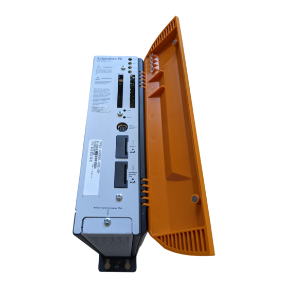
Drive inserts (hard disk, CD-ROM, DVD, burner, etc.) and up to two CompactFlash slots are hidden behind a cover on the front of the device. Figure 1: Automation PC 620 system overview Automation PC620 devices are available in two chipset versions. As a result, the Automation PC 620 covers a wide range of processor performance. -
Page 34: Features
• Heat sink (CPU board dependent) • Drive (mass memory such as CompactFlash card or hard disk) for the operating system • Software 1) Dependent on the device configuration and the environmental temperature. Automation PC 620 User's Manual V 1.90... -
Page 35: Selection Guide - Basic System
3) Select one each of main memory and heat sink, based on selected CPU board. 4) Select optional components, based on selected system unit (see Section 1.2.2 "Selection guide - optional components" on page 36). Automation PC 620 User's Manual V 1.90... -
Page 36: Selection Guide - Optional Components
Depending on the system unit, a compatible fan kit can be installed in the APC620. Required for certain system configurations and environmental temperatures (see also Sections 2.4 "Environmental temperatures for systems with an 815E CPU board" on Automation PC 620 User's Manual V 1.90... - Page 37 APC620. Only possible with system units 5PC600.SX02-00, 5PC600.SX05-00 and with an 855GME CPU board. • An optional interface adds an additional connection possibility. • The appropriate power supply plugs ensure simple connection to the power supply. Automation PC 620 User's Manual V 1.90...
-
Page 38: Entire Device
APC620 must be sent for repair. Removal of the mounting screws, which can be determined by a broken seal, voids all warranty. During operation, surface temperatures of the heat sink may reach 70 °C (warning "hot surface"). Automation PC 620 User's Manual V 1.90... - Page 39 The orange front doors contain two permanent magnets. Contact between a data carrier that saves data magnetically (hard disk, diskette, the magnetic strip of a credit card, etc.) and a magnet can cause loss of data. Automation PC 620 User's Manual V 1.90...
-
Page 40: Technical Data
7 A, max. 40 A for < 300 µs Power consumption Component-dependent, see Section 2.6 "Power management for APC620 systems with 1 and 2 PCI slots" Table 19: Technical data - APC620, 1 PCI slot variant Automation PC 620 User's Manual V 1.90... - Page 41 2) at 50 °C, 8.5 µA of the supplied components and a self discharge of 40%. 3) Depending on the process or batch, there may be visual deviations in the color and surface structure. 4) Maximum values, as long as no other individual component specify any other. Automation PC 620 User's Manual V 1.90...
-
Page 42: Dimensions
± 0.2 mm ± 0.3 mm over 30 to 120 mm over 120 to 400 mm ± 0.5 mm over 400 to 1000 mm ± 0.8 mm Figure 6: APC620, 1PCI slot variant dimensions Automation PC 620 User's Manual V 1.90... -
Page 43: Apc620, 2 Pci Slot Variant
APC620 must be sent for repair. Removal of the mounting screws, which can be determined by a broken seal, voids all warranty. During operation, surface temperatures of the heat sink may reach 70 °C (warning "hot surface"). Automation PC 620 User's Manual V 1.90... - Page 44 The orange front doors contain two permanent magnets. Contact between a data carrier that saves data magnetically (hard disk, diskette, the magnetic strip of a credit card, etc.) and a magnet can cause loss of data. Automation PC 620 User's Manual V 1.90...
-
Page 45: Technical Data
7 A, max. 40 A for < 300 µs Power consumption Component-dependent, see Section 2.6 "Power management for APC620 systems with 1 and 2 PCI slots" Table 20: Technical data - APC620, 2 PCI slot variant Automation PC 620 User's Manual V 1.90... - Page 46 2) at 50 °C, 8.5 µA of the supplied components and a self discharge of 40%. 3) Depending on the process or batch, there may be visual deviations in the color and surface structure. 4) Maximum values, as long as no other individual component specify any other. Automation PC 620 User's Manual V 1.90...
-
Page 47: Dimensions
30 to 120 mm ± 0.3 mm over 120 to 400 mm ± 0.5 mm 104.5 over 400 to 1000 mm ± 0.8 mm Figure 9: APC620, 2 PCI slot variant dimensions Automation PC 620 User's Manual V 1.90... -
Page 48: Apc620, 5 Pci Slot Variant
APC620 must be sent for repair. Removal of the mounting screws, which can be determined by a broken seal, voids all warranty. During operation, surface temperatures of the heat sink may reach 70 °C (warning "hot surface"). Automation PC 620 User's Manual V 1.90... - Page 49 Bottom slide-in slot 1 eject drive Before ejecting a drive the cover of the Automation PC 620 must be opened Figure 11: APC620, 5 PCI slot variant interface overview front Information: The orange front doors contain two permanent magnets. Contact between a data carrier that saves data magnetically (hard disk, diskette, the magnetic strip of a credit card, etc.) and a magnet can cause loss of data.
-
Page 50: Technical Data
10 A, max. 40 A for < 300 µs Power consumption Component-dependent, see Section 2.7 "Power management, APC620 systems with 5 PCI slots" Table 21: Technical data - APC620, 5 PCI slot variant Automation PC 620 User's Manual V 1.90... - Page 51 2) at 50 °C, 8.5 µA of the supplied components and a self discharge of 40%. 3) Depending on the process or batch, there may be visual deviations in the color and surface structure. 4) Maximum values, as long as no other individual component specify any other. Automation PC 620 User's Manual V 1.90...
-
Page 52: Dimensions
30 to 120 mm ± 0.3 mm over 120 to 400 mm ± 0.5 mm over 400 to 1000 mm 185.3 ± 0.8 mm Figure 12: APC620, 5 PCI slot variant dimensions Automation PC 620 User's Manual V 1.90... -
Page 53: Environmental Temperatures For Systems With An 815E Cpu Board
CPU module heat build-up PCI cards heat build-up main heat dissipation via heat sink PCI card(s) CPU module Slide-in drive(s) Add-on drive View from above Figure 13: Example of worst-case conditions for temperature measurement Automation PC 620 User's Manual V 1.90... - Page 54 In connection with one of the following components, the minimum environmental temperature is +5 °C: 5AC600.HDDI-00, 5AC600.CDXS-00, 5AC600.DVDS-00, 5AC600.DVRS-00, 5AC600.FDDS-00, 5AC600.HDDS-00, 5ACPCI.RAIS-00, 5ACPCI.RAIS-01. If none of the components that were mentioned are used, then the minimum environmental temperature is 0 °C. Automation PC 620 User's Manual V 1.90...
-
Page 55: How Do You Determine The Maximum Environmental Temperature
1) 24-hour operation = 732 POH (Power On Hours) per month, standard operation = 250 POH or 333 POH (Power On Hours) per month. 2) The measured temperature is a guideline for the immediate environmental temperature, but can be influenced by neighboring components. Automation PC 620 User's Manual V 1.90... -
Page 56: Environmental Temperatures For Systems With An 855Gme Cpu Board
CPU module heat build-up PCI cards heat build-up main heat dissipation via heat sink PCI card(s) CPU module Slide-in drive(s) Add-on drive View from above Figure 15: Example of worst-case conditions for temperature measurement Automation PC 620 User's Manual V 1.90... - Page 57 In connection with one of the following components, the minimum environmental temperature is +5 °C: 5AC600.HDDI-00, 5AC600.CDXS-00, 5AC600.DVDS-00, 5AC600.DVRS-00, 5AC600.FDDS-00, 5AC600.HDDS-00, 5ACPCI.RAIS-00, 5ACPCI.RAIS-01. If none of the components that were mentioned are used, then the minimum environmental temperature is 0 °C. Automation PC 620 User's Manual V 1.90...
-
Page 58: How Do You Determine The Maximum Environmental Temperature
1) 24-hour operation = 732 POH (Power On Hours) per month, standard operation = 250 POH or 333 POH (Power On Hours) per month. 2) The measured temperature is a guideline for the immediate environmental temperature, but can be influenced by neighboring components. Automation PC 620 User's Manual V 1.90... -
Page 59: Power Management For Apc620 Systems With 1 And 2 Pci Slots
After the system is turned on (e.g. using the power button), the voltages 3V3, 5 V, +12 V are placed on the bus. At the 5 V output, yet another DC/DC converter generates -12 V , and places these on the bus. Automation PC 620 User's Manual V 1.90... -
Page 60: Power Consumption With System Unit 5Pc600.Sx01-00 1 Pci
2) An external device can only be connected to the baseboard with Revision B7 or later of system unit 5PC600.SX01-00. A 1A multi-fuse is used. Starting current with system unit 5PC600.SX01-00 1 PCI The starting current is typically 7 A. The peak starting current is maximum 40 A in a time frame less than 300 µs. Automation PC 620 User's Manual V 1.90... -
Page 61: Power Consumption With System Unit 5Pc600.Sx02-00 2 Pci
2) An external device can only be connected to the baseboard with Revision B0 or later of system unit 5PC600.SX02-00. A 1A multi-fuse is used. Starting current with system unit 5PC600.SX02-00 2 PCI The starting current is typically 7 A. The peak starting current is maximum 40 A in a time frame less than 300 µs. Automation PC 620 User's Manual V 1.90... -
Page 62: Power Consumption With System Unit 5Pc600.Sx02-01 2 Pci
2) An external device can only be connected to the baseboard with Revision B9 or later of system unit 5PC600.SX02-01. A 1A multi-fuse is used. Starting current with system unit 5PC600.SX02-01 2 PCI The starting current is typically 7 A. The peak starting current is maximum 40 A in a time frame less than 300 µs. Automation PC 620 User's Manual V 1.90... -
Page 63: Power Management, Apc620 Systems With 5 Pci Slots
After the system is turned on (e.g. using the power button), the voltages 3V3, 5 V, +12 V are placed on the bus. At the 5 V output, yet another DC/DC converter generates -12 V , and places these on the bus. Automation PC 620 User's Manual V 1.90... -
Page 64: Power Consumption With System Unit 5Pc600.Sx05-00 5 Pci
1) The total performance of one PCI card per PCI slot (= sum of power consumptions for each voltage area) may not exceed the limits stated for operation with or without a fan kit. 2) An external device can only be connected to the baseboard with Revision A0 or later of system unit 5PC600.SX05-00. A 1A multi-fuse is used. Automation PC 620 User's Manual V 1.90... - Page 65 Technical data • Entire device Starting current with system unit 5PC600.SX05-00 5 PCI The starting current is typically 10 A. The peak starting current is maximum 40 A in a time frame less than 300 µs. Automation PC 620 User's Manual V 1.90...
-
Page 66: Power Consumption With System Unit 5Pc600.Sx05-01 5 Pci
1) The total performance of one PCI card per PCI slot (= sum of power consumptions for each voltage area) may not exceed the limits stated for operation with or without a fan kit. 2) An external device can only be connected to the baseboard with Revision A0 or later of system unit 5PC600.SX05-01. A 1A multi-fuse is used. Automation PC 620 User's Manual V 1.90... -
Page 67: Humidity Specifications
The listed tasks correspond to the humidity at an environmental temperature of 30 °C. More detailed information about the specific temperature-dependent humidity values can be found in the technical data of the individual components. Automation PC 620 User's Manual V 1.90... -
Page 68: General Device Interfaces
(optional) Reset and Power buttons PS/2 keyboard or mouse Battery Hardware security key (Dongle) Figure 20: General device interfaces Each individual device interface is explained in greater detail on the following pages. Automation PC 620 User's Manual V 1.90... -
Page 69: Serial Interfaces Com1
The setting for the I/O address and the IRQ can be changed in the BIOS setup (under "Advanced" - submenu "I/O Device Configuration" setting "Serial port A"). Please note any potential conflicts with other resources when changing this setting. Automation PC 620 User's Manual V 1.90... -
Page 70: Serial Interfaces Com2
The setting for the I/O address and the IRQ can be changed in the BIOS setup (under "Advanced" - submenu "I/O device configuration" setting "Serial port B"). Please note any potential conflicts with other resources when changing this setting. Automation PC 620 User's Manual V 1.90... -
Page 71: Ethernet Connection Eth1
Special drivers are necessary for operating the Intel Ethernet controller 82562. Drivers for Windows XP Professional, Windows XP Embedded, and DOS are available for download on the B&R homepage in the download area (www.br-automation.com). Automation PC 620 User's Manual V 1.90... -
Page 72: Ethernet Connection Eth2
Special drivers are necessary for operating the Intel Ethernet controller 82551ER. Drivers for Windows XP Professional, Windows XP Embedded, and DOS are available for download on the B&R homepage in the download area (www.br-automation.com Automation PC 620 User's Manual V 1.90... -
Page 73: Usb Port
For optimal functionality of USB 2.0 (transfer speed up to 480 Mbit/s) with Windows XP, at least Service Pack 1 must be installed. Without the Service Pack, Windows XP will only support USB 1.1. USB 2.0 comes already integrated in B&Rs XP embedded operating systems. Automation PC 620 User's Manual V 1.90... -
Page 74: Vdc Supply Voltage
Technical data • Entire device 2.9.6 +24 VDC supply voltage The Automation PC 620 has a 24 VDC ATX compatible power supply. Depending on the system unit, the power supply provides the following maximum performances (in watts). System unit Max. performance Max. - Page 75 System 2 PCI, 1 disk drive slot Starting with revision F0 5PC600.SX05-00 System 5 PCI, 2 disk drive slots, 1 AP Link slot Starting with revision D0 Table 31: System unit revisions for any standby times Automation PC 620 User's Manual V 1.90...
-
Page 76: Monitor / Panel Connection
The RGB, DVI and SDL cables can only be plugged in and unplugged when the APC620 and display device (Automation Panel 900, monitor) are turned off. See "Definitions for RGB, DVI, SDL" on page 79 for descriptions of RGB, DVI and SDL. Automation PC 620 User's Manual V 1.90... - Page 77 5CASDL.0100-00 5CASDL.0100-00 5CASDL.0100-00 5CASDL.0100-00 5CASDL.0100-00 5CASDL.0100-01 5CASDL.0100-01 5CASDL.0100-01 5CASDL.0100-01 5CASDL.0100-01 5CASDL.0150-00 5CASDL.0150-00 5CASDL.0150-00 5CASDL.0150-00 5CASDL.0150-01 5CASDL.0150-01 5CASDL.0150-01 5CASDL.0150-01 5CASDL.0200-00 5CASDL.0200-00 5CASDL.0200-00 5CASDL.0200-00 5CASDL.0250-00 5CASDL.0250-00 5CASDL.0250-00 Table 33: Segment lengths, resolutions and SDL cable Automation PC 620 User's Manual V 1.90...
- Page 78 System 5 PCI, 2 disk drive slots, 1 AP Link slot Rev. C0 5PC600.SX05-01 System 5 PCI, 2 disk drive slots Rev. C0 Table 35: Requirements for SDL cable with extender and automatic cable adjustment (equalizer) Automation PC 620 User's Manual V 1.90...
- Page 79 Figure 25: Monitor / Panel connection with DVI video signal For examples and possibilities for connecting Automation Panel 900 display units via DVI, see Appendix A, Chapter 3 "Commissioning", Section 3 "Connection examples - Automation Panel 900", starting on page 176. Automation PC 620 User's Manual V 1.90...
-
Page 80: Mic, Line In And Line Out Port
Special drivers are necessary for operating the AC97 sound chip (Realtek). Drivers for Windows XP Professional and Windows XP Embedded are available for download on the B&R homepage in the download area (www.br-automation.com Automation PC 620 User's Manual V 1.90... -
Page 81: Add-On Interface Slot
2.9.10 AP Link slot The option of inserting and using an AP Link card is only possible with system units 5PC600.SX02-00 and 5PC600.SX05-00. For more information see Section 3.10 "AP Link cards" on page 158. Automation PC 620 User's Manual V 1.90... -
Page 82: Pci Slots
2 PCI slots" on page 59). Technical data Features PCI bus properties Default PCI 2.2 Design Half Size PCI PCI bus type 32-bit PCI bus speed 33 MHz Table 38: Technical data - PCI bus Automation PC 620 User's Manual V 1.90... - Page 83 5 volt PCI card Dual-voltage PCI card universal card 5 V and 3.3 V compatible 5 volt plug 3.3 volt plug Supply on plug: 5 and 3.3 volts Figure 28: PCI connector type: 5 volt Automation PC 620 User's Manual V 1.90...
-
Page 84: Status Leds
Link 2 Yellow In preparation Table 39: Technical data - Status LEDs The light for the status LEDs is fed to the front cover via fiber optic lines. Figure 29: Front-side status LEDs Automation PC 620 User's Manual V 1.90... -
Page 85: Compactflash Slot (Cf1)
CompactFlash 1024 MB SSI 5CFCRD.2048-03 CompactFlash 2048 MB SSI 5CFCRD.4096-03 CompactFlash 4096 MB SSI Table 40: Technical data - CompactFlash slot (CF1) Warning! The power must be shut off before inserting or removing the CompactFlash card! Automation PC 620 User's Manual V 1.90... -
Page 86: Hard Disk / Compactflash Slot (Hdd/Cf2)
CompactFlash 2048 MB SSI 5CFCRD.4096-03 CompactFlash 4096 MB SSI Table 41: Technical data - hard disk / CompactFlash slot (HDD/CF2) Warning! The power must be shut off before inserting or removing the CompactFlash card! Automation PC 620 User's Manual V 1.90... -
Page 87: Power Button
The reset button can be pressed with a pointed object (i.e. paper clip or tip of a pen). Pushing the reset button results in a hardware-reset, PCI- reset. The Automation PC 620 restarts cold. The MTCX processor is not reset when the reset button is pressed. -
Page 88: Ps/2 Keyboard/Mouse
BIOS. In order to do this, set "PS/2 mouse" in the BIOS setup menu to "enabled" and save. (Located under Advanced - Miscellaneous - Item "PS/2 mouse"). Automation PC 620 User's Manual V 1.90... -
Page 89: Battery
Lithium battery, 1 pc., 3 V / 950 mAh, button cell Table 45: Technical data - battery For more on changing the lithium battery, see Chapter 7 "Maintenance / Servicing", Section "Changing the battery" on page 441. Automation PC 620 User's Manual V 1.90... -
Page 90: Hardware Security Key
Table 47: Hardware security key - I/O address and IRQ The setting for the I/O address and the IRQ can be changed in the BIOS setup (under "Advanced" - submenu "I/O device configuration" setting "Parallel port"). Automation PC 620 User's Manual V 1.90... -
Page 91: Slide-In Slot 1 Drive Slot
5AC600.DVDS-00 Slide-in DVD-ROM/CD-RW 5AC600.DVRS-00 Slide-in DVD-R/RW, DVD+R/RW 5AC600.FDDS-00 Slide-in USB FDD 5AC600.HDDS-00 Slide-in hard disk 30 GB 24x7 5AC600.HDDS-01 Slide-in hard disk 20 GB ET Table 48: Technical data - slide-in slot 1 Automation PC 620 User's Manual V 1.90... -
Page 92: Slide-In Slot 2 Drive Slot
5AC600.DVDS-00 Slide-in DVD-ROM/CD-RW 5AC600.DVRS-00 Slide-in DVD-R/RW, DVD+R/RW 5AC600.FDDS-00 Slide-in USB FDD 5AC600.HDDS-00 Slide-in hard disk 30 GB 24x7 5AC600.HDDS-01 Slide-in hard disk 20 GB ET Table 49: Technical data - slide-in slot 2 Automation PC 620 User's Manual V 1.90... -
Page 93: Serial Number Sticker
This information can also be found on the B&R homepage. Enter the serial number of the entire device (found behind the front door) in the serial number search field on the start page www.br- automation.com. The search provides you with a detailed list of the individual components. Automation PC 620 User's Manual V 1.90... - Page 94 Technical data • Entire device Serial number entry e.g. 70950170564 List of installed components after the serial number searc Figure 32: Example of serial number search: 70950170564 Automation PC 620 User's Manual V 1.90...
-
Page 95: Block Diagram
Winbond Serial 2 switch RS232 W83627HF Floppy Kontroller Dallas security Exterior interface key controller Optional or interior interface Figure 33: Block diagram of entire device with system unit 5PC600.SX01-00 and 855GME CPU board Automation PC 620 User's Manual V 1.90... -
Page 96: Entire Device With System Unit 5Pc600.Sx02-00
Winbond Serial 2 Switching RS232 W83627HF Floppy controller Dallas security Exterior interface key controller Optional or interior interface Figure 34: Block diagram of entire device with system unit 5PC600.SX02-00 and 855GME CPU board Automation PC 620 User's Manual V 1.90... -
Page 97: Entire Device With System Unit 5Pc600.Sx02-01
Winbond Serial 2 switch RS232 W83627HF Floppy controller Dallas security Exterior interface key controller Optional or internal interface Figure 35: Block diagram of entire device with system unit 5PC600.SX02-01 and 855GME CPU board Automation PC 620 User's Manual V 1.90... -
Page 98: Entire Device With System Unit 5Pc600.Sx05-00
Winbond Serial 2 switch RS232 W83627HF Floppy controller Dallas security Exterior interface key controller Optional or internal interface Figure 36: Block diagram of entire device with system unit 5PC600.SX05-00 and 855GME CPU board Automation PC 620 User's Manual V 1.90... -
Page 99: Entire Device With System Unit 5Pc600.Sx05-01
Winbond Serial 2 switch RS232 W83627HF Floppy controller Dallas security External interface key controller Optional or interior interface Figure 37: Block diagram of entire device with system unit 5PC600.SX05-01 and 855GME CPU board Automation PC 620 User's Manual V 1.90... -
Page 100: Individual Components
Combined CompactFlash slot 2 / hard Yes, optional add-on CompactFlash slot or add-on hard disk disk (HDD/CF2) Internal organization Primary slave Insert for slide-in drive 1 Internal organization Secondary slave Table 50: Technical data - system units Automation PC 620 User's Manual V 1.90... - Page 101 1) Maintenance Controller Extended, for more information, see the section "Maintenance Controller Extended (MTCX)" on page 461. 2) Depending on the process or batch, there may be visual deviations in the color and surface structure. Automation PC 620 User's Manual V 1.90...
-
Page 102: Cpu Boards 815E
Chipset Intel 82815E (GMCH) Intel 82801DB (ICH4) - integrated real-time clock (RTC) Features 5PC600.E815-00 5PC600.E815-02 5PC600.E815-03 Front side bus 100 MHz 133 MHz 133 MHz Table 51: Technical data - CPU boards 815E Automation PC 620 User's Manual V 1.90... - Page 103 In order for the CPU board with the Intel 82815E chipset to work properly, it is necessary to install the Intel chipset driver (e.g. special USB driver) and the graphic chip. The necessary software can be downloaded from the download area on the B&R homepage (www.br- automation.com). Automation PC 620 User's Manual V 1.90...
-
Page 104: Cpu Boards 855Gme
32 KB Floating Point Unit (FPU) 1 MB 1 MB 2 MB 2 MB 512 kB 1 MB Features 5PC600.E855-00 5PC600.E855-01 5PC600.E855-02 5PC600.E855-03 5PC600.E855-04 5PC600.E855-05 Table 52: Technical data - CPU boards 855GME Automation PC 620 User's Manual V 1.90... - Page 105 In order for the CPU board with the Intel 82855GME chipset to work properly, it is necessary to install the Intel chipset driver (e.g. special USB driver) and the graphic chip. They can be downloaded from the download area on the B&R homepage (www.br-automation.com Automation PC 620 User's Manual V 1.90...
-
Page 106: Heat Sink
5PC600.E855-05 Material Black-coated aluminum Outer dimensions Width 228.7 mm 228.7 mm Height 218 mm 218 mm Depth 12.8 mm 30 mm Weight 1340 g 1640 g Table 53: Technical data - heat sink Automation PC 620 User's Manual V 1.90... -
Page 107: Main Memory
SO-DIMM SDRAM SDRAM SDRAM DDR-SDRAM DDR-SDRAM DDR-SDRAM Organization 16Mx64 32Mx64 64Mx64 32Mx64 64Mx64 128Mx64 Table 54: Technical data - main memory Information: A main memory can only be replaced at the B&R plant. Automation PC 620 User's Manual V 1.90... -
Page 108: Drives
30 GB Number of heads Number of sectors (user) 58.605.120 Bytes per sector Revolution speed 4200 rpm ± 1% Access time (average) 7.14 ms Table 55: Technical data - add-on hard disk 5AC600.HDDI-00 Automation PC 620 User's Manual V 1.90... - Page 109 - 300 to 12000 meters Table 55: Technical data - add-on hard disk 5AC600.HDDI-00 (cont.) 1) Standard operation means 250 POH (power-on hours) per month. 2) 24-hour operation means 732 POH (power-on hours) per month. Automation PC 620 User's Manual V 1.90...
- Page 110 Technical data • Individual components Temperature humidity diagram for operation and storage 24-hour Storage operation Temperature [°C] Figure 43: Temperature humidity diagram for add-on hard disk 5AC600.HDDI-00 Automation PC 620 User's Manual V 1.90...
-
Page 111: Add-On Hard Disk 20 Gb Et - 5Ac600.Hddi-01
20 GB Number of heads Number of sectors (user) 39,070,080 Bytes per sector Revolution speed 4200 rpm ± 1% Access time (average) 7.14 ms Table 56: Technical data - add-on hard disk 5AC600.HDDI-01 Automation PC 620 User's Manual V 1.90... - Page 112 0-peak) and 11 ms duration Altitude Operation - 300 to 3000 meters Storage - 300 to 12000 meters Table 56: Technical data - add-on hard disk 5AC600.HDDI-01 (cont.) 1) Operation means 250 POH (power-on hours) per month. Automation PC 620 User's Manual V 1.90...
- Page 113 Technical data • Individual components Temperature humidity diagram for operation and storage Storage Operation Temperature [°C] Figure 45: Temperature humidity diagram for add-on hard disk 5AC600.HDDI-01 Automation PC 620 User's Manual V 1.90...
-
Page 114: Add-On Compactflash Slot - 5Ac600.Cfsi-00
Type I Number 1 slot Connection Primary slave Weight 100 g Table 57: Technical data - add-on CompactFlash slot 5AC600.CFSI-00 Warning! The power must be shut off before inserting or removing the CompactFlash card! Automation PC 620 User's Manual V 1.90... -
Page 115: Slide-In Cd-Rom - 5Ac600.Cdxs-00
The following characteristics, features and limit values are only valid for these individual components and can deviate from those for the entire device. For the entire device in which these individual components are used, refer to the data given specifically for the entire device. Automation PC 620 User's Manual V 1.90... - Page 116 200 g for 2 ms Transportation at max. 60 g for 11 ms at max. 200 g for 2 ms Table 58: Technical data - slide-in CD-ROM 5AC600.CDXS-00 1) Drive surface temperature Automation PC 620 User's Manual V 1.90...
- Page 117 Technical data • Individual components Temperature humidity diagram for operation and storage Storage Operation Temperature [°C] Figure 48: Temperature humidity diagram for slide-in CD-ROM - 5AC600.CDXS-00 Automation PC 620 User's Manual V 1.90...
-
Page 118: Slide-In Dvd-Rom/Cd-Rw - 5Ac600.Dvds-00
The following characteristics, features and limit values are only valid for these individual components and can deviate from those for the entire device. For the entire device in which these individual components are used, refer to the data given specifically for the entire device. Automation PC 620 User's Manual V 1.90... - Page 119 5 - 500 Hz and 0.2 g Storage at max. 5 - 500 Hz and 2 g Transportation at max. 5 - 500 Hz and 2 g Table 59: Technical data - slide-in DVD-ROM/CD-RW - 5AC600.DVDS-00 Automation PC 620 User's Manual V 1.90...
- Page 120 Table 59: Technical data - slide-in DVD-ROM/CD-RW - 5AC600.DVDS-00 (cont.) 1) Drive surface temperature Temperature humidity diagram for operation and storage Storage Operation Temperature [°C] Figure 50: Temperature humidity diagram for slide-in DVD-ROM/CD-RW - 5AC600.DVDS-00 Automation PC 620 User's Manual V 1.90...
-
Page 121: Slide-In Dvd-R/Rw, Dvd+R/Rw - 5Ac600.Dvrs-00
The following characteristics, features and limit values are only valid for these individual components and can deviate from those for the entire device. For the entire device in which these individual components are used, refer to the data given specifically for the entire device. Automation PC 620 User's Manual V 1.90... - Page 122 Environmental temperature Operation +5 °C .. +55 °C Storage -20 °C .. +60 °C Transportation -40 °C .. +65 °C Table 60: Technical data - slide-in DVD-R/RW, DVD+R/RW - 5AC600.DVRS-00 revision D0 and higher Automation PC 620 User's Manual V 1.90...
- Page 123 Readable media CD/CD-ROM (12 cm, 8 cm), CD-R, CD-RW DVD-ROM, DVD-R, DVD-RW Non-write protected media CD-R, CD-RW DVD-R/RW, DVD+R/RW Table 61: Technical data - slide-in DVD-R/RW, DVD+R/RW - 5AC600.DVRS-00 revision D0 and lower Automation PC 620 User's Manual V 1.90...
- Page 124 60 g for 11 ms at max. 200 g for 2 ms Table 61: Technical data - slide-in DVD-R/RW, DVD+R/RW - 5AC600.DVRS-00 revision D0 and lower (cont.) 1) Drive surface temperature Automation PC 620 User's Manual V 1.90...
- Page 125 Technical data • Individual components Temperature humidity diagram for operation and storage Transport Storage Operation Temperature [°C] Figure 52: Temperature humidity diagram for slide-in DVD-R/RW, DVD+R/RW - 5AC600.DVRS-00 Automation PC 620 User's Manual V 1.90...
-
Page 126: Slide-In Cf 2 Slot - 5Ac600.Cfss-00
The power must be switched off to the APC620 before inserting the CompactFlash card into, or removing it from, the CF3 IDE CompactFlash slot! Activity LED (CF3) Eject CF3 via Activity LED (CF4) Eject CF4 via Figure 53: Slide-in CF 2-slot - 5AC600.CFSS-00 Automation PC 620 User's Manual V 1.90... - Page 127 IDE - Secondary master in slide-in slot 2 Activity LED CompactFlash (CF4) Type Type I and II Number 1 slot Connection Via USB 2.0 Activity LED Table 62: Technical data - slide-in CF 2 slot - 5AC600.CFSS-00 Automation PC 620 User's Manual V 1.90...
-
Page 128: Slide-In Usb Fdd - 5Ac600.Fdds-00
In system units with 5 PCI slots, the slide-in USB FDD drive must be inserted in slide-in slot 1 for mechanical reasons. Caution! Turn off power before adding or removing a slide-in drive. Figure 54: Slide-in USB FDD - 5AC600.FDDS-00 Automation PC 620 User's Manual V 1.90... - Page 129 5 g for 11 ms Storage at max. 60 g for 11 ms Transportation at max. 60 g for 11 ms Altitude Max. 3,000 meters Table 63: Technical data - slide-in USB diskette drive - 5AC600.FDDS-00 Automation PC 620 User's Manual V 1.90...
- Page 130 Technical data • Individual components Temperature humidity diagram for operation and storage Storage Operation Temperature [°C] Figure 55: Temperature humidity diagram for slide-in USB diskette drive - 5AC600.FDDS-00 Automation PC 620 User's Manual V 1.90...
-
Page 131: Slide-In Hard Disk 30 Gb 24X7 - 5Ac600.Hdds-00
It is possible to add or remove a slide-in drive at any time. Caution! Turn off power before adding or removing a slide-in drive. Figure 56: Slide-in hard disk 30 GB - 5AC600.HDDS-00 Automation PC 620 User's Manual V 1.90... - Page 132 300,000 hours Mechanical characteristics Slide-in mounting Fixed Outer dimensions (without slide-in) Width 70 mm Length 100 mm Height 9.5 mm Weight 120 g Table 64: Technical data - slide-in hard disk - 5AC600.HDDS-00 Automation PC 620 User's Manual V 1.90...
- Page 133 2) 24-hour operation means 732 POH (power-on hours) per month. Temperature humidity diagram for operation and storage 24-hour Storage operation Temperature [°C] Figure 57: Temperature humidity diagram for slide-in hard disk - 5AC600.HDDS-00 Automation PC 620 User's Manual V 1.90...
-
Page 134: Slide-In Hard Disk 20 Gb Et - 5Ac600.Hdds-01
The following characteristics, features and limit values are only valid for these individual components and can deviate from those for the entire device. For the entire device in which these individual components are used, refer to the data given specifically for the entire device. Automation PC 620 User's Manual V 1.90... - Page 135 No damage at max. 900 g (8820 m/s 0-peak) and 1 ms duration No damage at max. 120 g (1176 m/s 0-peak) and 11 ms duration Table 65: Technical data - slide-in hard disk - 5AC600.HDDS-01 Automation PC 620 User's Manual V 1.90...
- Page 136 Table 65: Technical data - slide-in hard disk - 5AC600.HDDS-01 (cont.) 1) Operation means 250 POH (power-on hours) per month. Temperature humidity diagram for operation and storage Storage Operation Temperature [°C] Figure 59: Temperature humidity diagram for slide-in hard disk - 5AC600.HDDS-01 Automation PC 620 User's Manual V 1.90...
-
Page 137: Raid System
As a result, parallel access to two hard drives with a relatively high data throughput is the main focus, in addition to the high availability. File A File B File C File D File A File B File C File D Figure 60: RAID 1 System schematic Automation PC 620 User's Manual V 1.90... -
Page 138: Pci Raid Controller Ata/100 - 5Acpci.raic-00
RAID Level Supports RAID 0, 1, 0/1 and JBOD Internal connections Two 40-pin connections Electrical characteristics Power consumption 0.15 A at 5 V (PCI bus) Table 66: Technical data - RAID controller - 5ACPCI.RAIC-00 Automation PC 620 User's Manual V 1.90... - Page 139 Drivers for the approved operating systems can be downloaded from the download area on the B&R homepage (www.br-automation.com). Contents of delivery Number Component Adaptec ATA RAID 1200A controller ATA RAID connection cable (length 130 mm) Table 67: Contents of delivery - 5ACPCI.RAIC-00 Automation PC 620 User's Manual V 1.90...
-
Page 140: Pci Raid Storage 2 X 40 Gb - 5Acpci.rais-00
PCI RAID storage drives are only available factory-installed. Therefore, they need to be requested when placing the order. Primary hard disk Primary Secondary Access LED (yellow) for primary Secondary hard disk and secondary hard disks Figure 62: PCI RAID storage - 5ACPCI.RAIS-00 Automation PC 620 User's Manual V 1.90... - Page 141 +5 °C .. +55 °C Operation - 24-hour +5 °C .. +40 °C Storage -40 °C .. +65 °C Transportation -40 °C .. +65 °C Table 68: Technical data - RAID hard disk - 5ACPCI.RAIS-00 Automation PC 620 User's Manual V 1.90...
- Page 142 3) 24-hour operation means 732 POH (power-on hours) per month. Temperature humidity diagram for operation and storage 24-hour Storage operation Temperature [°C] Figure 63: Temperature humidity diagram - RAID hard disk - 5ACPCI.RAIS-00 Automation PC 620 User's Manual V 1.90...
-
Page 143: Pci Raid Storage 2 X 60 Gb - 5Acpci.rais-01
PCI RAID storage drives are only available factory-installed. Therefore, they need to be requested when placing the order. Primary hard disk Primary Secondary Access LED (yellow) for primary Secondary hard disk and secondary hard disks Figure 64: PCI RAID storage - 5ACPCI.RAIS-01 Automation PC 620 User's Manual V 1.90... - Page 144 +5 °C .. +55 °C Operation - 24-hour +5 °C .. +40 °C Storage -40 °C .. +65 °C Transportation -40 °C .. +65 °C Table 69: Technical data - RAID hard disk - 5ACPCI.RAIS-01 Automation PC 620 User's Manual V 1.90...
- Page 145 3) 24-hour operation means 732 POH (power-on hours) per month. Temperature humidity diagram for operation and storage 24-hour Storage operation Temperature [°C] Figure 65: Temperature humidity diagram - RAID hard disk - 5ACPCI.RAIS-01 Automation PC 620 User's Manual V 1.90...
-
Page 146: Interface Options
CAN interface Controller Intel 82527 Number Connection 9-pin DSUB, male Terminating resistors Can be activated and deactivated using a sliding switch Default setting Disabled Table 71: Technical data - add-on CAN interface - 5AC600.CANI-00 Automation PC 620 User's Manual V 1.90... - Page 147 The type of cable used depends largely on the required bus length and the number of nodes. The bus length is mainly determined by the bit rate. In accordance with CiA (CAN in Automation) the maximum bus length is 1000 meters. Automation PC 620 User's Manual V 1.90...
- Page 148 CAN networks are cabled using a bus structure where both ends of the bus are equipped with terminating resistors. The add-on CAN interface has an integrated terminating resistor (delivery state: disabled with the setting "Off"). Figure 66: Terminating resistor for add-on CAN interface 5AC600.CANI-00 Automation PC 620 User's Manual V 1.90...
-
Page 149: Add-On Rs232/422/485 Interface - 5Ac600.485I-00
(RS232/RS422/RS485) is selected automatically, depending on the electrical connection. Order data Model number Description Image 5AC600.485I-00 Add-on RS232/422/485 interface Add-on RS232/422/485 interface for installation in an APC620 and PPC700. Table 76: Add-on RS232/422/485 interface - 5AC600.485I-00 Automation PC 620 User's Manual V 1.90... - Page 150 The maximum transfer rate of 115 kBit/s depends on the cable type being used. Distance [m] Transfer rate [kBit/s] ≤ 15 Type 64 ≤ 10 Type 115 ≤ 5 Type 115 Table 79: RS232 bus length and transfer rate Automation PC 620 User's Manual V 1.90...
- Page 151 1 x 0.34 mm² (22AWG/19), tinned Cu wire Wire insulation ≤ 59 Ohm / km Conductor resistance Outer sheathing Material PUR mixture Properties Halogen free Entire shielding From tinned cu wires Table 82: RS422 cable requirements Automation PC 620 User's Manual V 1.90...
- Page 152 1 x 0.34 mm² (22AWG/19), tinned Cu wire Wire insulation ≤ 59 Ohm / km Conductor resistance Outer sheathing Material PUR mixture Properties Halogen free Entire shielding From tinned cu wires Table 84: RS485 cable requirements Automation PC 620 User's Manual V 1.90...
- Page 153 Technical data • Individual components Contents of delivery The screws included in the mounting kit are to be used for installation. Figure 69: Contents of the delivery / mounting material - 5AC600.485I-00 Automation PC 620 User's Manual V 1.90...
-
Page 154: Fan Kit
Depending on the work environment, the dust filter should be checked with appropriate frequency to determine whether the air flow provides sufficient cooling. An exchange or cleaning of the filter kit is appropriate at that time. Table 85: Technical data - 5PC600.FA01-00 Automation PC 620 User's Manual V 1.90... -
Page 155: Fan Kit 2 Pci - 5Pc600.Fa02-00
Figure 71: Fan kit - 5PC600.FA02-00 Technical data Features 5PC600.FA02-00 Fan type Double ball bearings Width 60 mm Length 60 mm Height 20 mm Revolution speed 3600 rpm ± 10% Table 87: Technical data - 5PC600.FA02-00 Automation PC 620 User's Manual V 1.90... -
Page 156: Fan Kit 5 Pci - 5Pc600.Fa05-00
This fan kit is an optional addition for system units with 5 PCI slots. Fan ø 60 mm Fans ø 80 mm Filter clasp Cable clamp Fastening screws Dust filter Figure 72: Fan kit - 5PC600.FA05-00 Automation PC 620 User's Manual V 1.90... - Page 157 Table 90: Contents of delivery - 5PC600.FA05-00 Installation For a description of how to install the fan kit, see Chapter 7 "Maintenance / Servicing", Section 2 "Fan kit installation and replacement", starting on page 444. Automation PC 620 User's Manual V 1.90...
-
Page 158: Ap Link Cards
Monitor / Panel 5AC600.SDL0-00 DVI, SDL RGB, DVI, SDL Monitor / Panel output Table 92: AP Link slot (AP Link card inserted) Hotplug for a display device is not supported in any combination. Automation PC 620 User's Manual V 1.90... - Page 159 XUSB0- n.c. XUSB0+ n.c. + 5 V Power n.c. Ground (return for + 5V, HSync and VSync) Table 93: Pin assignments - AP Link connection 1) Protected internally by a multifuse Automation PC 620 User's Manual V 1.90...
- Page 160 SDLR, SDLT) V01.10, available in the SDLT FPGA Firmware on the AP Link SDL transceiver v 00.02 download area of the B&R homepage. Table 96: Requirements for SDL cable with extender and automatic cable adjustment (equalizer) Automation PC 620 User's Manual V 1.90...
- Page 161 Figure 74: AP Link device connection with DVI video signal For examples and possibilities for connecting Automation Panel 900 display units via DVI, see Appendix A, Chapter 3 "Commissioning", Section 3 "Connection examples - Automation Panel 900", starting on page 176. Automation PC 620 User's Manual V 1.90...
- Page 162 Figure 75: AP Link device connection with SDL video signal For examples and possibilities for connecting Automation Panel 900 display units via SDL, see Appendix A, Chapter 3 "Commissioning", Section 3 "Connection examples - Automation Panel 900", starting on page 176. Automation PC 620 User's Manual V 1.90...
-
Page 163: Chapter 3: Commissioning
Be sure the wall or switching cabinet can withstand four times the total weight of the PC620. • When connecting certain cable types (DVI, SDL, USB, etc.), keep the flex radius in mind. (see Section Automation PC 620 User's Manual V 1.90... -
Page 164: Drilling Templates
Commissioning • Installation 1.2 Drilling templates APC620 with 1 PCI slot APC620 with 2 PCI slots Mounting plate template (APC620) Mounting plate template (APC620) Table 97: Drilling templates - 1 and 2 PCI slots Automation PC 620 User's Manual V 1.90... - Page 165 Commissioning • Installation APC620 with 5 PCI slots Mounting plate template (APC620) Table 98: Drilling template - 5 PCI slots Automation PC 620 User's Manual V 1.90...
-
Page 166: Mounting Orientation
APC620 systems with and without fan kit can be mounted this way. Figure 77: Mounting orientation - standard In order to guarantee natural air circulation, mount the system so that the spacing on the top, bottom, and sides is as follows. Automation PC 620 User's Manual V 1.90... - Page 167 Commissioning • Installation at least air out 100 mm at least at least 50 mm 50 mm at least air in 100 mm Figure 78: Air circulation spacing - standard Automation PC 620 User's Manual V 1.90...
-
Page 168: Optional Mounting Orientations
(CD-ROM, DVD/CD- RW, hard disk, etc.). See the following pages for information regarding the specifications for mounting orientation. Figure 79: Optional mounting orientations Automation PC 620 User's Manual V 1.90... - Page 169 50 mm Figure 80: Optional circulation spacing CompactFlash slot, add-on or slide-in No limitation on mounting orientation. Permissible mounting orientations are shown in Figure 79 "Optional mounting orientations" on page 168. Automation PC 620 User's Manual V 1.90...
- Page 170 1) Only allowed when a fan kit is used. Figure 81: Mounting orientations for an APC620 with hard disk drive. The mounting orientations "horizontal 1" and "horizontal 2" require the use of a fan kit. Automation PC 620 User's Manual V 1.90...
- Page 171 Figure 82: Mounting orientations for an APC 620 with a slide-in CD-ROM drive The mounting orientation "horizontal 1" requires the use of a fan kit. Mounting orientation "vertical 1" can also be used at 0° without a fan kit. Automation PC 620 User's Manual V 1.90...
- Page 172 Figure 83: Mounting orientations for an APC620 with a slide-in DVD-ROM/CD-RW drive The mounting orientation "horizontal 1" requires the use of a fan kit. Mounting orientation "vertical 1" can also be used at 0° without a fan kit. Automation PC 620 User's Manual V 1.90...
- Page 173 Figure 84: Mounting orientations for an APC620 with a slide-in DVD-R/RW / DVD+R/RW drive The mounting orientation "horizontal 1" requires the use of a fan kit. Mounting orientation "vertical 1" can also be used at 0° without a fan kit. Automation PC 620 User's Manual V 1.90...
- Page 174 1) Only allowed when a fan kit is used. Figure 85: Mounting orientations for an APC620 with a slide-in USB FDD drive Mounting orientation "vertical 1" can also be used at 0° without a fan kit. Automation PC 620 User's Manual V 1.90...
-
Page 175: Cable Connections
Figure 86: Flex radius - cable connection Information: The value specified for the minimum flex radius can be found in the technical data for the cable that is being used. Automation PC 620 User's Manual V 1.90... -
Page 176: Connection Examples - Automation Panel 900
Do BIOS settings have to be changed for a specific configuration? Information: An RGB monitor / flat-screen can always be connected to the monitor / panel output of the APC620 (necessary DVI to CRT adapter can be ordered under the model number 5AC900.1000-00). Automation PC 620 User's Manual V 1.90... -
Page 177: Configuration - One Automation Panel Via Dvi
5PC600.SX01-00 5PC600.SX02-00 5PC600.SX02-01 5PC600.SX05-00 5PC600.SX05-01 5PC600.E855-00 Max. SXGA 5PC600.E855-01 Max. SXGA 5PC600.E855-02 Max. SXGA 5PC600.E855-03 Max. SXGA 5PC600.E855-04 Max. SXGA 5PC600.E855-05 Max. SXGA Table 99: Possible combinations of system unit and CPU board Automation PC 620 User's Manual V 1.90... -
Page 178: Link Modules
1) USB support is not possible on the Automation Panel 900 because USB is limited up to 5 m. Information: The DVI transfer mode does not allow reading statistical values on Automation Panel 900 units. Automation PC 620 User's Manual V 1.90... -
Page 179: Bios Settings
3.1.5 BIOS settings No special BIOS settings are necessary for operation. 3.1.6 Windows graphics driver settings See Chapter 4 "Software", Section 4 "Automation PC 620 with Windows XP Professional" on page 335. 3.1.7 Windows touch driver settings See Chapter 4 "Software", Section 4 "Automation PC 620 with Windows XP Professional" on page 335. -
Page 180: Configuration - One Automation Panel Via Sdl
Table 103: Possible combinations of system unit and CPU board 3.2.2 Link modules Model number Description Note 5DLSDL.1000-00 Automation Panel Link SDL Receiver for Automation Panel Table 104: Link module for the configuration - One Automation Panel via SDL Automation PC 620 User's Manual V 1.90... -
Page 181: Cable
5CASDL.0400-10 Table 106: Segment lengths, resolutions and SDL cable The cable types and resolutions shown in blue in the previous table can only be implemented starting with the following firmware and hardware versions: Automation PC 620 User's Manual V 1.90... -
Page 182: Bios Settings
3.2.5 Windows graphics driver settings "Digital display" must be defined as output device in the graphics driver. For more information on this, see Chapter 4 "Software", Section 4 "Automation PC 620 with Windows XP Professional" on page 335. Automation PC 620 User's Manual V 1.90... -
Page 183: Windows Touch Driver Settings
Commissioning • Connection examples - Automation Panel 900 3.2.6 Windows touch driver settings For more information on this, see Chapter 4 "Software", Section 4 "Automation PC 620 with Windows XP Professional" on page 335. Automation PC 620 User's Manual V 1.90... -
Page 184: Configuration - Four Automation Panels Via Sdl On One Line
5PC600.SX01-00 5PC600.SX02-00 5PC600.SX02-01 5PC600.SX05-00 5PC600.SX05-01 5PC600.E855-00 Max. UXGA 5PC600.E855-01 Max. UXGA 5PC600.E855-02 Max. UXGA 5PC600.E855-03 Max. UXGA 5PC600.E855-04 Max. UXGA 5PC600.E855-05 Max. UXGA Table 109: Possible combinations of system unit and CPU board Automation PC 620 User's Manual V 1.90... -
Page 185: Link Modules
5CASDL.0018-01 5CASDL.0018-01 5CASDL.0018-01 5CASDL.0018-01 5CASDL.0018-01 5CASDL.0050-00 5CASDL.0050-00 5CASDL.0050-00 5CASDL.0050-00 5CASDL.0050-00 5CASDL.0050-01 5CASDL.0050-01 5CASDL.0050-01 5CASDL.0050-01 5CASDL.0050-01 5CASDL.0100-00 5CASDL.0100-00 5CASDL.0100-00 5CASDL.0100-00 5CASDL.0100-00 5CASDL.0100-01 5CASDL.0100-01 5CASDL.0100-01 5CASDL.0100-01 5CASDL.0100-01 Table 112: Segment lengths, resolutions and SDL cable Automation PC 620 User's Manual V 1.90... - Page 186 System 5 PCI, 2 disk drive slots, 1 AP Link slot Rev. C0 5PC600.SX05-01 System 5 PCI, 2 disk drive slots Rev. C0 Table 114: Requirements for SDL cable with extender and automatic cable adjustment (equalizer) Automation PC 620 User's Manual V 1.90...
-
Page 187: Bios Settings
"Display Clone" must be defined as output device in the graphics driver, with "Digital Display" as primary device. For more information on this, see Chapter 4 "Software", Section 4 "Automation PC 620 with Windows XP Professional" on page 335. 3.3.6 Windows touch screen driver settings For more information on this, see Chapter 4 "Software", Section 4 "Automation PC 620 with... -
Page 188: Configuration - One Automation Panel Via Sdl (Optional)
5PC600.SX01-00 5PC600.SX02-00 5PC600.SX02-01 5PC600.SX05-00 5PC600.SX05-01 5PC600.E855-00 Max. UXGA 5PC600.E855-01 Max. UXGA 5PC600.E855-02 Max. UXGA 5PC600.E855-03 Max. UXGA 5PC600.E855-04 Max. UXGA 5PC600.E855-05 Max. UXGA Table 115: Possible combinations of system unit and CPU board Automation PC 620 User's Manual V 1.90... -
Page 189: Link Modules
5CASDL.0018-01 5CASDL.0018-01 5CASDL.0018-01 5CASDL.0018-01 5CASDL.0018-01 5CASDL.0050-00 5CASDL.0050-00 5CASDL.0050-00 5CASDL.0050-00 5CASDL.0050-00 5CASDL.0050-01 5CASDL.0050-01 5CASDL.0050-01 5CASDL.0050-01 5CASDL.0050-01 5CASDL.0100-00 5CASDL.0100-00 5CASDL.0100-00 5CASDL.0100-00 5CASDL.0100-00 5CASDL.0100-01 5CASDL.0100-01 5CASDL.0100-01 5CASDL.0100-01 5CASDL.0100-01 Table 118: Segment lengths, resolutions and SDL cable Automation PC 620 User's Manual V 1.90... - Page 190 System 5 PCI, 2 disk drive slots, 1 AP Link slot Rev. C0 5PC600.SX05-01 System 5 PCI, 2 disk drive slots Rev. C0 Table 120: Requirements for SDL cable with extender and automatic cable adjustment (equalizer) Automation PC 620 User's Manual V 1.90...
-
Page 191: Bios Settings
3.4.5 Windows graphics driver settings "Notebook" must be defined as output device in the graphics driver. For more information on this, see Chapter 4 "Software", Section 4 "Automation PC 620 with Windows XP Professional" on page 335. 3.4.6 Windows touch driver settings For more information on this, see Chapter 4 "Software", Section 4 "Automation PC 620 with... -
Page 192: Configuration - Four Automation Panels Via Sdl (Optional) On One Line
5PC600.SX01-00 5PC600.SX02-00 5PC600.SX02-01 5PC600.SX05-00 5PC600.SX05-01 5PC600.E855-00 Max. UXGA 5PC600.E855-01 Max. UXGA 5PC600.E855-02 Max. UXGA 5PC600.E855-03 Max. UXGA 5PC600.E855-04 Max. UXGA 5PC600.E855-05 Max. UXGA Table 121: Possible combinations of system unit and CPU board Automation PC 620 User's Manual V 1.90... -
Page 193: Link Modules
640 x 480 800 x 600 1024 x 768 1280 x 1024 1600 x 1200 5CASDL.0018-00 5CASDL.0018-00 5CASDL.0018-00 5CASDL.0018-00 5CASDL.0018-00 5CASDL.0018-01 5CASDL.0018-01 5CASDL.0018-01 5CASDL.0018-01 5CASDL.0018-01 Table 124: Segment lengths, resolutions and SDL cable Automation PC 620 User's Manual V 1.90... - Page 194 5PC600.SX01-00 System 1 PCI Rev. E0 5PC600.SX02-00 System 2 PCI, 1 disk drive slot, 1 AP Link slot Rev. D0 Table 126: Requirements for SDL cable with extender and automatic cable adjustment (equalizer) Automation PC 620 User's Manual V 1.90...
-
Page 195: Bios Settings
3.5.5 Windows graphics driver settings "Notebook" must be defined as output device in the graphics driver. For more information on this, see Chapter 4 "Software", Section 4 "Automation PC 620 with Windows XP Professional" on page 335. 3.5.6 Windows touch driver settings For more information on this, see Chapter 4 "Software", Section 4 "Automation PC 620 with... -
Page 196: Configuration - Two Automation Panels Via Sdl And Sdl (Optional)
5PC600.SX01-00 5PC600.SX02-00 5PC600.SX02-01 5PC600.SX05-00 5PC600.SX05-01 5PC600.E855-00 Max. UXGA 5PC600.E855-01 Max. UXGA 5PC600.E855-02 Max. UXGA 5PC600.E855-03 Max. UXGA 5PC600.E855-04 Max. UXGA 5PC600.E855-05 Max. UXGA Table 127: Possible combinations of system unit and CPU board Automation PC 620 User's Manual V 1.90... -
Page 197: Link Modules
5CASDL.0018-01 5CASDL.0018-01 5CASDL.0018-01 5CASDL.0018-01 5CASDL.0018-01 5CASDL.0050-00 5CASDL.0050-00 5CASDL.0050-00 5CASDL.0050-00 5CASDL.0050-00 5CASDL.0050-01 5CASDL.0050-01 5CASDL.0050-01 5CASDL.0050-01 5CASDL.0050-01 5CASDL.0100-00 5CASDL.0100-00 5CASDL.0100-00 5CASDL.0100-00 5CASDL.0100-00 5CASDL.0100-01 5CASDL.0100-01 5CASDL.0100-01 5CASDL.0100-01 5CASDL.0100-01 Table 130: Segment lengths, resolutions and SDL cable Automation PC 620 User's Manual V 1.90... - Page 198 System 5 PCI, 2 disk drive slots, 1 AP Link slot Rev. C0 5PC600.SX05-01 System 5 PCI, 2 disk drive slots Rev. C0 Table 132: Requirements for SDL cable with extender and automatic cable adjustment (equalizer) Automation PC 620 User's Manual V 1.90...
-
Page 199: Bios Settings
= disabled). 3.6.5 Windows graphics driver settings See Chapter 4 "Software", Section 4 "Automation PC 620 with Windows XP Professional" on page 335. If all connected Automation Panel 900 displays (line 1 + line 2) should display the same content, then "Dual Display Clone"... -
Page 200: Configuration - Eight Automation Panels Via Sdl And Sdl (Optional)
Link: 5DLSDL.1000-01 panel number Link: 5DLSDL.1000-01 not possible not possible Link: 5DLSDL.1000-01 Link: 5DLSDL.1000-01 not possible not possible Link: 5DLSDL.1000-00 Link: 5DLSDL.1000-00 Figure 93: Configuration - Eight Automation Panels via SDL and SDL (optional) Automation PC 620 User's Manual V 1.90... -
Page 201: Basic System Requirements
SDL without extender 10 m 5CASDL.0100-01 SDL without extender with 45° plug 10 m 5CASDL.0150-00 SDL without extender 15 m 5CASDL.0150-01 SDL without extender with 45° plug 15 m Table 135: Cable for SDL configurations Automation PC 620 User's Manual V 1.90... - Page 202 B&R homepage. Hardware Description Revision Note 5DLSDL.1000-00 AP Link SDL receiver Rev. B0 5DLSDL.1000-01 AP Link SDL transceiver Rev. B0 Table 137: Requirements for SDL cable with automatic cable adjustment (equalizer) Automation PC 620 User's Manual V 1.90...
-
Page 203: Bios Settings
= disabled). 3.7.5 Windows graphics driver settings See Chapter 4 "Software", Section 4 "Automation PC 620 with Windows XP Professional" on page 335. If all connected Automation Panel 900 displays (line 1 + line 2) should display the same content, then "Dual Display Clone"... - Page 204 Commissioning • Connection examples - Automation Panel 900 Automation PC 620 User's Manual V 1.90...
-
Page 205: Chapter 4: Software
1.1.1 General information BIOS stands for "Basic Input Output System." It is the most basic standardized communication between the user and the system (hardware). The BIOS system used in the Automation PC 620 systems is produced by Phoenix. The BIOS setup utility lets you modify basic system configuration settings. These settings are stored in CMOS and in EEPROM (as a backup). - Page 206 Software • Automation PC 620 with BIOS When these "preliminary steps" are finished, BIOS searches for an operating system in the data storage devices available (hard drive, floppy drive, etc.). BIOS launches the operating system and hands over control of system operations to it.
-
Page 207: Bios Setup Keys
Software • Automation PC 620 with BIOS Figure 95: 815E - BIOS summary screen 1.1.3 BIOS setup keys The following keys are active during the POST: Function Enters the BIOS setup menu. Cues the boot menu. Lists all bootable devices that are connected to the system. With cursor ↑ and cursor ↓... - Page 208 Software • Automation PC 620 with BIOS Function <F9> Loads setup defaults for the current BIOS setup screen. <F10> Saves settings and closes BIOS setup. <Enter> Opens submenu for a BIOS setup menu item, or displays the configurable values of a BIOS setup item.
-
Page 209: Main
Software • Automation PC 620 with BIOS 1.1.4 Main Figure 96: 815E - main menu BIOS setting Description Setting options Effect System time This is the current system time setting. Adjustment of the Set the system time in the format (hh:mm:ss). - Page 210 Software • Automation PC 620 with BIOS BIOS setting Description Setting options Effect Smart device S.M.A.R.T. (Self Monitoring Analysis and Enabled Activates this function. In the future, a message monitoring Reporting Technology) is implemented in regarding impending errors is produced.
- Page 211 Software • Automation PC 620 with BIOS BIOS setting Description Setting options Effect Type The type of drive connected to the primary Auto Automatic recognition of the drive and setup of master is configured here. appropriate values. User Manual setup of the drive (number of cylinders, heads, and sectors).
- Page 212 Software • Automation PC 620 with BIOS Primary slave Figure 98: 815E - primary slave setup BIOS setting Description Setting options Effect Type The type of drive connected to the primary Auto Automatic recognition of the drive and setup of slave is configured here.
- Page 213 Software • Automation PC 620 with BIOS BIOS setting Description Setting options Effect 32-bit I/O This function enables 32-bit data transfer. Disabled Disables this function. Enabled Enables this function. Transfer mode The communication path between the Default Default setting primary slave drive and the system Fast PIO 1 - Fast PIO 4 / Manual configuration of PIO mode.
- Page 214 Software • Automation PC 620 with BIOS Secondary master Figure 99: 815E - secondary master setup BIOS setting Description Setting options Effect Type The type of drive connected to the Auto Automatic recognition of the drive and setup of secondary master is configured here.
- Page 215 Software • Automation PC 620 with BIOS BIOS setting Description Setting options Effect 32-bit I/O This function enables 32-bit data transfer. Disabled Disables this function. Enabled Enables this function. Transfer mode The communication path between the Default Default setting secondary master drive and the system Fast PIO 1 - Fast PIO 4 / Manual configuration of PIO mode.
- Page 216 Software • Automation PC 620 with BIOS Secondary slave Figure 100: 815E - secondary slave setup BIOS setting Description Setting options Effect Type The type of drive connected to the Auto Automatic recognition of the drive and setup of secondary slave is configured here.
- Page 217 Software • Automation PC 620 with BIOS BIOS setting Description Setting options Effect 32-bit I/O This function enables 32-bit data transfer. Disabled Disables this function. Enabled Enables this function. Transfer mode The communication path between the Default Default setting secondary slave drive and the system Fast PIO 1 - Fast PIO 4 / Manual configuration of PIO mode.
-
Page 218: Advanced
Software • Automation PC 620 with BIOS 1.1.5 Advanced Figure 101: 815E - advanced menu BIOS setup menu Description Setting options Effect Advanced Setup of advanced chipset and graphics Enter Opens submenu chipset/graphics functions. see "Advanced chipset/graphics control" on control page 219. - Page 219 Software • Automation PC 620 with BIOS Advanced chipset/graphics control Figure 102: 815E - advanced chipset/graphics control Automation PC 620 User's Manual V 1.90...
- Page 220 Software • Automation PC 620 with BIOS BIOS setting Description Setting options Effect Graphics engine Settings can be made for the onboard Auto Automatic setting of the resolution (using a read- video controller. out of the connected panel's EDID data).
- Page 221 Software • Automation PC 620 with BIOS PCI/PNP configuration Figure 103: 815E - PCI/PNP configuration BIOS setting Description Setting options Effect PNP OS installed If the operating system The ISA PnP resources are not assigned. The is plug & play capable, then this option...
- Page 222 Software • Automation PC 620 with BIOS BIOS setting Description Setting options Effect PCI device, slot #1 Advanced configuration of the PCI slot Enter Opens submenu number 1. See "PCI device, slot #1" on page 223 PCI device, slot #2...
- Page 223 Software • Automation PC 620 with BIOS BIOS setting Description Setting options Effect Assign IRQ to SMB Use this function to set whether or not the Enabled Automatic assignment of a PCI interrupt. SM (System Management) bus controller Disabled No assignment of an interrupt.
- Page 224 Software • Automation PC 620 with BIOS PCI device, slot #2 Figure 105: 815E - PCI device, slot #2 BIOS setting Description Setting options Effect ROM scan option Setting for the initialization of a device's Enabled Enables this function. ROM.
- Page 225 Software • Automation PC 620 with BIOS PCI device, slot #3 Figure 106: 815E - PCI device, slot #3 BIOS setting Description Setting options Effect ROM scan option Setting for the initialization of a device's Enabled Enables this function. ROM.
- Page 226 Software • Automation PC 620 with BIOS PCI device, slot #4 Figure 107: 815E - PCI device, slot #4 BIOS setting Description Setting options Effect ROM scan option Setting for the initialization of a device's Enabled Enables this function. ROM.
- Page 227 Software • Automation PC 620 with BIOS PCI/PNP ISA IRQ resource exclusion Figure 108: 815E - PCI/PNP ISA IRQ resource exclusion BIOS setting Description Setting options Effect IRQ 3 This setting determines whether the IRQ 3 Available It is available for PCI devices.
- Page 228 Software • Automation PC 620 with BIOS BIOS setting Description Setting options Effect IRQ 12 This setting determines whether the IRQ Available It is available for PCI devices. 12 is reserved for legacy ISA devices. Reserved It is reserved for ISA devices.
- Page 229 Software • Automation PC 620 with BIOS BIOS setting Description Setting options Effect Cache extended Configure how the memory content of the Uncached No mapping. memory area system memory above 1MB should be Write through Memory content is simultaneously mapped in the mapped.
- Page 230 Software • Automation PC 620 with BIOS I/O device configuration Figure 110: 815E - I/O device configuration BIOS setting Description Setting options Effect Local bus IDE Enable or disable one or both of the Disabled Deactivates both PCI IDE controllers (primary...
- Page 231 Software • Automation PC 620 with BIOS BIOS setting Description Setting options Effect USB UHCI host Configuration of the USB UHCI controller Disabled Deactivates the USB support. controller 1 1 for USB port 0 und 1. Enabled Activates the USB support.
- Page 232 Software • Automation PC 620 with BIOS BIOS setting Description Setting options Effect Base I/O address Selection of the base I/O address for port 3F8, 2F8, 3E8, 2E8 Selected base I/O address is manually assigned. A yellow star indicates a conflict with another device.
- Page 233 Software • Automation PC 620 with BIOS BIOS setting Description Setting options Effect NumLock This option sets the status Numeric keypad is activated. of the numeric keypad when the the Only the cursor functions of the numerical keypad system is booted.
- Page 234 Software • Automation PC 620 with BIOS BIOS setting Description Setting options Effect VCC 3.3V voltage Displays the current voltage of the 3.3 volt None supply (in volts). CPU core voltage Displays the processor's core voltage (in None volts). 5Vsb voltage Displays the 5 V standby voltage (in volts).
- Page 235 Software • Automation PC 620 with BIOS BIOS setting Description Setting options Effect Extended memory This function determines the method by Just zero it The main memory is quickly tested. testing which the main memory over 1 MB is None The main memory is not tested at all.
- Page 236 Software • Automation PC 620 with BIOS Baseboard/panel features Figure 114: 815E - baseboard / panel features BIOS setting Description Setting options Effect Panel control For special setup of connected panels Enter Opens submenu (display units). See "Panel control" on page 237...
- Page 237 Software • Automation PC 620 with BIOS BIOS setting Description Setting options Effect Serial number Displays the B&R serial number. None Product name Displays the B&R model number. None User serial ID Displays the hexadecimal value of the None user serial ID number.
- Page 238 Software • Automation PC 620 with BIOS BIOS setting Description Setting options Effect Temperature Displays the selected panel's temperature None (in degrees Celsius and Fahrenheit). Fan speed Displays fan RPMs of the selected panel. None Keys/LEDs Displays the available keys and LEDs on None the selected panel.
- Page 239 Software • Automation PC 620 with BIOS BIOS setting Description Setting options Effect Case 1 Displays the fan RPMs of housing fan 1. None Case 2 Displays the fan RPMs of housing fan 2. None Case 3 Displays the fan RPMs of housing fan 3.
- Page 240 Software • Automation PC 620 with BIOS BIOS setting Description Setting options Effect Interrupt Selection of the interrupt for the COM C IRQ 3, IRQ 4, IRQ 5, IRQ Selected interrupt is assigned. port. 10, IRQ 11, IRQ 12, IRQ A yellow star indicates a conflict with another device.
-
Page 241: Security
Software • Automation PC 620 with BIOS 1.1.6 Security Figure 118: 815E - security menu BIOS setting Description Setting options Effect Supervisor Displays whether or not a supervisor None Display set: A supervisor password has been set. password is password has been set. - Page 242 Software • Automation PC 620 with BIOS BIOS setting Description Setting options Effect Diskette access Access to the diskette drive is controlled Supervisor Supervisor password is needed to access a here. Either or the supervisor or the user diskette drive.
-
Page 243: Power
Software • Automation PC 620 with BIOS 1.1.7 Power Figure 119: 815E - power menu BIOS setting Description Setting options Effect Enable ACPI This option turns the ACPI function Enables this function. (Advanced Configuration and Power Interface) on or off. This is an advanced plug &... - Page 244 Software • Automation PC 620 with BIOS BIOS setting Description Setting options Effect Standby timeout Set here when the system should enter No standby. standby mode. During standby, various devices and the display will be deactivated. 1, 2, 4, 8 minutes Time in minutes until standby.
- Page 245 Software • Automation PC 620 with BIOS ACPI control Figure 120: 815E - ACPI control BIOS setting Description Setting options Effect Active trip point With this function, an optional CPU fan Disabled Disables this function. above the operating system can be set to 40 °C...
- Page 246 Software • Automation PC 620 with BIOS BIOS setting Description Setting options Effect APIC - I/O APIC mode This option controls the functionality of the Disabled Deactivates the function advanced interrupt controller in the Enabled Enables this function. processor. The activation of this option is only effective if it takes place before the operating system (Windows XP) is activated.
-
Page 247: Boot
Software • Automation PC 620 with BIOS BIOS setting Description Setting options Effect Temperature Temperature limit for the setting "auto 75°C ... 110°C Can be set in increments of 5°C. thermal throttling." Hysteresis When auto thermal throttling has been 3°C ... 6°C Can be set in increments of 1°C. -
Page 248: Exit
Software • Automation PC 620 with BIOS BIOS setting Description Setting options Effect Use the up arrow ↑ and down arrow ↓ , to select IDE 0, IDE 1, IDE 2, IDE 3, a device. Then, use the <+> und <-> keys to IDE CD change the boot priority of the drive. -
Page 249: Profile Overview
Software • Automation PC 620 with BIOS BIOS setting Description Setting options Effect Exit discarding With this item you can close BIOS setup Yes / No changes without saving the changes made. The system is then rebooted. Load setup defaults... - Page 250 Software • Automation PC 620 with BIOS DIP switch setting Number Optimized for Profile 4 Panel PC 700 system unit 5PC720.1043-01, 5PC720.1505-01 and 5PC720.1505-02. Table 170: 815E - profile overview (cont.) 1) Reserved. The following pages provide an overview of the BIOS default settings for the different DIP switch configurations.
- Page 251 Software • Automation PC 620 with BIOS Secondary master Type Auto Auto Auto Auto Auto Multi-sector transfer LBA mode control 32-bit I/O Disabled Disabled Disabled Disabled Disabled Transfer mode Secondary master Ultra DMA mode SMART monitoring Disabled Disabled Disabled Disabled...
- Page 252 Software • Automation PC 620 with BIOS Onboard LAN IRQ line Auto-select Auto-select Auto-select Auto-select Auto-select Onboard USB EHCI IRQ Auto-select Auto-select Auto-select Auto-select Auto-select line Default primary video adapter Assign IRQ to SMB Enabled Enabled Enabled Enabled Enabled PCI device, slot #1...
- Page 253 Software • Automation PC 620 with BIOS Memory cache Profile 0 Profile 1 Profile 2 Profile 3 Profile 4 Personal settings Memory cache Enabled Enabled Enabled Enabled Enabled Cache system BIOS area Write protect Write protect Write protect Write protect...
- Page 254 Software • Automation PC 620 with BIOS Keyboard features Profile 0 Profile 1 Profile 2 Profile 3 Profile 4 Personal settings NumLock Key click Disabled Disabled Disabled Disabled Disabled Keyboard auto-repeat rate 30/sec 30/sec 30/sec 30/sec 30/sec Keyboard auto-repeat delay...
- Page 255 Software • Automation PC 620 with BIOS Device ID Compatibility ID Serial number Product name User serial ID Panel control Select panel number Version Brightness 100 % 100 % 100 % 100 % 100 % Temperature Fan speed Keys/LEDs Baseboard monitor...
- Page 256 Software • Automation PC 620 with BIOS Disabled Disabled Disabled Disabled Disabled Base I/O address Interrupt 2nd LAN controller Enabled Enabled Enabled Enabled Enabled Table 179: 815E - baseboard/panel features - profile setting overview (cont.) Security Profile 0 Profile 1...
- Page 257 Software • Automation PC 620 with BIOS APIC - I/O APIC mode Disabled Enabled Disabled Disabled Disabled Native IDE support Disabled Disabled Disabled Disabled Disabled Thermal management Auto thermal throttling Enabled Enabled Enabled Enabled Enabled Temperature 100°C 100°C 100°C 100°C 100°C...
-
Page 258: 855Gme - Bios Description
1.2.1 General information BIOS stands for "Basic Input Output System." It is the most basic standardized communication between the user and the system (hardware). The BIOS system used in the Automation PC 620 systems is produced by Phoenix. The BIOS setup utility lets you modify basic system configuration settings. These settings are stored in CMOS and in EEPROM (as a backup). - Page 259 Software • Automation PC 620 with BIOS Figure 125: 855GME - BIOS diagnostics screen Summary screen After the POST, the summary screen displays the most important system characteristics. Figure 126: 855GME - BIOS summary screen Automation PC 620 User's Manual V 1.90...
-
Page 260: Bios Setup Keys
Software • Automation PC 620 with BIOS 1.2.3 BIOS setup keys The following keys are active during the POST: Function Enters the BIOS setup menu. Cues the boot menu. Lists all bootable devices that are connected to the system. With cursor ↑ and cursor ↓... -
Page 261: Main
Software • Automation PC 620 with BIOS 1.2.4 Main Figure 127: 855GME - main BIOS setting Description Setting options Effect System time This is the current system time setting. Adjustment of the Set the system time in the format (hh:mm:ss). - Page 262 Software • Automation PC 620 with BIOS BIOS setting Description Setting options Effect IDE channel 1 The drive in the system that is connected Enter Opens submenu master to the IDE channel 1 master (previously see "IDE channel 1 master" on page 267.
- Page 263 Software • Automation PC 620 with BIOS IDE channel 0 master Figure 128: 855GME IDE channel 0 master setup BIOS setting Description Setting options Effect Type The type of drive connected to the IDE Auto Automatic recognition of the drive and setup of channel 0 master (previously "primary...
- Page 264 Software • Automation PC 620 with BIOS BIOS setting Description Setting options Effect 32-bit I/O This function enables 32-bit data transfer. Disabled Disables this function. Enabled Enables this function. Transfer mode The communication path between the IDE Default Default setting...
- Page 265 Software • Automation PC 620 with BIOS IDE channel 0 slave Figure 129: 855GME IDE channel 0 slave setup BIOS setting Description Setting options Effect Type The type of drive connected to the IDE Auto Automatic recognition of the drive and setup of channel 0 slave (previously "primary...
- Page 266 Software • Automation PC 620 with BIOS BIOS setting Description Setting options Effect 32-bit I/O This function enables 32-bit data transfer. Disabled Disables this function. Enabled Enables this function. Transfer mode The communication path between the IDE Default Default setting...
- Page 267 Software • Automation PC 620 with BIOS IDE channel 1 master Figure 130: 855GME IDE channel 1 master setup BIOS setting Description Setting options Effect Type The type of drive connected to the IDE Auto Automatic recognition of the drive and setup of channel 1 master (previously "secondary...
- Page 268 Software • Automation PC 620 with BIOS BIOS setting Description Setting options Effect 32-bit I/O This function enables 32-bit data transfer. Disabled Disables this function. Enabled Enables this function. Transfer mode The communication path between the IDE Default Default setting...
- Page 269 Software • Automation PC 620 with BIOS IDE channel 1 slave Figure 131: 855GME IDE channel 1 slave setup BIOS setting Description Setting options Effect Type The type of drive connected to the IDE Auto Automatic recognition of the drive and setup of channel 1 slave (previously "secondary...
- Page 270 Software • Automation PC 620 with BIOS BIOS setting Description Setting options Effect 32-bit I/O This function enables 32-bit data transfer. Disabled Disables this function. Enabled Enables this function. Transfer mode The communication path between the IDE Default Default setting...
-
Page 271: Advanced
Software • Automation PC 620 with BIOS 1.2.5 Advanced Figure 132: 855GME - advanced setup menu - overview BIOS setup menu Description Setting options Effect Advanced Setup of advanced chipset and graphics Enter Opens submenu chipset/graphics functions. see "Advanced chipset/graphics control" on control page 272. - Page 272 Software • Automation PC 620 with BIOS Advanced chipset/graphics control Figure 133: 855GME - advanced chipset control BIOS setting Description Setting options Effect Graphics engine 1 Settings can be made for the onboard Auto Automatic setting of the graphics engine 1. The video controller (internal graphics device).
- Page 273 Software • Automation PC 620 with BIOS BIOS setting Description Setting options Effect Default flat panel Should the connected panel fail to be None A predefined resolution has not been set. automatically recognized, a predefined VGA, SVGA, XGA, VGA = 640 x 480 resolution resolution can be set manually here.
- Page 274 Software • Automation PC 620 with BIOS PCI/PNP configuration Figure 134: 855GME - PCI/PNP configuration Automation PC 620 User's Manual V 1.90...
- Page 275 Software • Automation PC 620 with BIOS BIOS setting Description Setting options Effect PNP OS installed If the operating system The ISA PnP resources are not assigned. The is plug & play capable, then this option resource assignment sequence is as follows: informs BIOS that the operating system 1.
- Page 276 Software • Automation PC 620 with BIOS BIOS setting Description Setting options Effect Onboard LAN IRQ Under this option, the onboard LAN Auto-select The interrupt is automatically assigned according line interrupt is assigned to an ISA interrupt. to the plug & play guidelines.
- Page 277 Software • Automation PC 620 with BIOS PCI device, slot #1 Figure 135: 855GME - PCI device, slot #1 BIOS setting Description Setting options Effect ROM scan option Setting for the initialization of a device's Enabled Enables this function. ROM.
- Page 278 Software • Automation PC 620 with BIOS PCI device, slot #2 Figure 136: 855GME - PCI device, slot #2 BIOS setting Description Setting options Effect ROM scan option Setting for the initialization of a device's Enabled Enables this function. ROM.
- Page 279 Software • Automation PC 620 with BIOS PCI device, slot #3 Figure 137: 855GME - PCI device, slot #3 BIOS setting Description Setting options Effect ROM scan option Setting for the initialization of a device's Enabled Enables this function. ROM.
- Page 280 Software • Automation PC 620 with BIOS PCI device, slot #4 Figure 138: 855GME - PCI device, slot #4 BIOS setting Description Setting options Effect ROM scan option Setting for the initialization of a device's Enabled Enables this function. ROM.
- Page 281 Software • Automation PC 620 with BIOS Memory cache Figure 139: 855GME - memory cache BIOS setting Description Setting options Effect Memory cache Enable/ disable utilization of the L2 cache. Enabled Enables this function. Disabled Disables this function. Cache system BIOS...
- Page 282 Software • Automation PC 620 with BIOS BIOS setting Description Setting options Effect Cache base 512- Set whether the memory content should Uncached No mapping. 640k be mapped in the cache (512-640k), and Write through Memory content is simultaneously mapped in the when necessary, written in the main cache and written to the main memory.
- Page 283 Software • Automation PC 620 with BIOS I/O device configuration Figure 140: 855GME - I/O device configuration BIOS setting Description Setting options Effect Local bus IDE Enable or disable one or both of the Disabled Deactivates both PCI IDE controllers (primary...
- Page 284 Software • Automation PC 620 with BIOS BIOS setting Description Setting options Effect USB UHCI host Configuration of the USB UHCI controller Disabled Deactivates the USB support. controller 1 Enabled Activates the USB support. for USB port 0 und 1.
- Page 285 Software • Automation PC 620 with BIOS BIOS setting Description Setting options Effect Base I/O address Selection of the base I/O address for port 3F8, 2F8, 3E8, 2E8 Selected base I/O address is manually assigned. A yellow star indicates a conflict with another device.
- Page 286 Software • Automation PC 620 with BIOS BIOS setting Description Setting options Effect NumLock This option sets the status Numeric keypad is activated. of the numeric keypad when the the Only the cursor functions of the numerical keypad system is booted.
- Page 287 Software • Automation PC 620 with BIOS BIOS setting Description Setting options Effect VCC 3.3V voltage Displays the current voltage of the 3.3 volt None supply (in volts). CPU core voltage Displays the processor's core voltage (in None volts). 5Vsb voltage Displays the 5 V standby voltage (in volts).
- Page 288 Software • Automation PC 620 with BIOS BIOS setting Description Setting options Effect Extended memory This function determines the method by Just zero it The main memory is quickly tested. testing which the main memory over 1 MB is None The main memory is not tested at all.
- Page 289 Software • Automation PC 620 with BIOS Baseboard/panel features Figure 144: 855GME - baseboard/panel features BIOS setting Description Setting options Effect Panel control For special setup of connected panels. Enter Opens submenu see "Panel control" on page 290. Baseboard monitor...
- Page 290 Software • Automation PC 620 with BIOS BIOS setting Description Setting options Effect Serial number Displays the B&R serial number. None Product name Displays the B&R model number. None User serial ID Displays the hexadecimal value of the None user serial ID number.
- Page 291 Software • Automation PC 620 with BIOS BIOS setting Description Setting options Effect Temperature Displays the selected panel's temperature None (in degrees Celsius and Fahrenheit). Fan speed Displays fan RPMs of the selected panel. None Keys/LEDs Displays the available keys and LEDs on None the selected panel.
- Page 292 Software • Automation PC 620 with BIOS BIOS setting Description Setting options Effect Case 1 Displays the fan RPMs of housing fan 1. None Case 2 Displays the fan RPMs of housing fan 2. None Case 3 Displays the fan RPMs of housing fan 3.
- Page 293 Software • Automation PC 620 with BIOS BIOS setting Description Setting options Effect COM C Settings for the internal serial interfaces in Disabled Deactivates the interface. the system. This setting activates the Enabled Activates the interface. touch screen in panel PC 700 systems, and, using SDL transfer technology, also in Automation Panel 900 display units.
-
Page 294: Security
Software • Automation PC 620 with BIOS BIOS setting Description Setting options Effect 2nd LAN controller For turning the on-board LAN controller Disabled Deactivates the controller. (ETH2) on and off. Enabled Activates the controller. LAN1 MAC address Displays the MAC addresses for the ETH1 network controller. - Page 295 Software • Automation PC 620 with BIOS BIOS setting Description Setting options Effect Set supervisor To enter/change a supervisor password. Enter Press Enter and enter password two times. The password A supervisor password is necessary to maximum 7 password must be 7 alphanumeric characters or edit all BIOS settings.
-
Page 296: Power
Software • Automation PC 620 with BIOS 1.2.7 Power Figure 149: 855GME - power menu BIOS setting Description Setting options Effect Enable ACPI This option turns the ACPI function Enables this function. (Advanced Configuration and Power Interface) on or off. This is an advanced plug &... - Page 297 Software • Automation PC 620 with BIOS BIOS setting Description Setting options Effect Power savings This function determines if and how the Disabled Deactivates the power save function. power save function is used. Customized Power management is configured by adjusting the individual settings.
- Page 298 Software • Automation PC 620 with BIOS BIOS setting Description Setting options Effect Enable PME for This option enables the PME (Power OS control Evaluation of the PME signal is only active if it has Management Event) signal for controlling...
- Page 299 Software • Automation PC 620 with BIOS BIOS setting Description Setting options Effect Passive cooling trip With this function, a temperature can be Disabled Disables this function. point set at which the CPU automatically 40 °C .. 100 °C Temperature setting for the passive cooling trip reduces its speed.
-
Page 300: Boot
Software • Automation PC 620 with BIOS 1.2.8 Boot Figure 151: 855GME - boot menu BIOS setting Description Setting options Effect Use the up arrow ↑ and down arrow ↓ , to select IDE 0, IDE 1, IDE 2, IDE 3, a device. -
Page 301: Exit
Software • Automation PC 620 with BIOS 1.2.9 Exit Figure 152: 855GME - exit menu BIOS setting Description Setting options Effect Exit saving changes BIOS setup is closed with this item. Yes / No Changes made are saved in CMOS after confirmation, and the system is rebooted. -
Page 302: Profile Overview
Software • Automation PC 620 with BIOS 1.2.10 Profile overview If the function "load setup defaults" is chosen in the main BIOS setup menu, or if exit is selected (or <F9> is pressed) in the individual setup screens, the following BIOS settings are the optimized values that will be used. - Page 303 Software • Automation PC 620 with BIOS Main Profile 0 Profile 1 Profile 2 Profile 3 Profile 4 Personal settings System time System date SMART device monitoring Enabled Enabled Enabled Enabled Enabled IDE channel 0 master Type Auto Auto Auto...
- Page 304 Software • Automation PC 620 with BIOS Advanced Advanced chipset/graphics control Profile 0 Profile 1 Profile 2 Profile 3 Profile 4 Personal settings Graphics engine 1 Auto Auto Auto Auto Auto Default flat panel None None None None None Flat panel scaling...
- Page 305 Software • Automation PC 620 with BIOS PCI device, slot #3 Profile 0 Profile 1 Profile 2 Profile 3 Profile 4 Personal settings ROM scan option Enabled Enabled Enabled Enabled Enabled Enable master Disabled Disabled Disabled Disabled Disabled Latency timer...
- Page 306 Software • Automation PC 620 with BIOS I/O device configuration Profile 0 Profile 1 Profile 2 Profile 3 Profile 4 Personal settings Local bus IDE adapter Primary Both Both Primary Both Primary IDE UDMA66/100 Enabled Enabled Enabled Enabled Enabled Secondary IDE...
- Page 307 Software • Automation PC 620 with BIOS CPU board monitor Profile 0 Profile 1 Profile 2 Profile 3 Profile 4 Personal settings VCC 3.3V voltage CPU core voltage 5Vsb voltage Battery voltage CPU temperature Table 219: 855GME - CPU board monitor - profile setting overview...
- Page 308 Software • Automation PC 620 with BIOS Panel control Profile 0 Profile 1 Profile 2 Profile 3 Profile 4 Personal settings Select panel number Version Brightness 100 % 100 % 100 % 100 % 100 % Temperature Fan speed Keys/LEDs...
- Page 309 Software • Automation PC 620 with BIOS Security Profile 0 Profile 1 Profile 2 Profile 3 Profile 4 Personal settings Supervisor password is Clear Clear Clear Clear Clear User password is Clear Clear Clear Clear Clear Set supervisor password Set user password...
- Page 310 Software • Automation PC 620 with BIOS Boot Profile 0 Profile 1 Profile 2 Profile 3 Profile 4 Personal settings Boot priority order IDE 0 PCI BEV IDE 0 IDE 0 IDE 0 IDE 1 IDE 0 IDE 1 IDE 1...
-
Page 311: Bios Postcode Messages
Software • Automation PC 620 with BIOS 1.3 BIOS postcode messages While the Automation PC 620 is booting, the following messages and errors can occur with BIOS. These errors are signaled by different beeping codes. Beeping code Description Necessary user action... -
Page 312: Distribution Of Resources
Software • Automation PC 620 with BIOS 1.4 Distribution of resources 1.4.1 RAM address assignment RAM address Resource 000000h - 0003FFh Interrupt vectors 000400h - 09FFFFh MS-DOS Program Area 0A0000h - 0AFFFFh VGA Graphics 0B8000h - 0BBFFFh VGA Text Mode... -
Page 313: I/O Address Assignment
Software • Automation PC 620 with BIOS 1.4.3 I/O address assignment I/O address Resource 000h - 01Fh DMA controller 1 020h - 03Fh Interrupt controller 1 040h - 05Fh Timer 060h - 06Fh Keyboard controller 070h - 071h Real-time clock, NMI mask, CMOS... -
Page 314: Interrupt - Assignments In Pci Mode
Software • Automation PC 620 with BIOS 1.4.4 Interrupt - Assignments in PCI mode System timer Keyboard IRQ cascade COM1 (Serial port A) COM2 (Serial port B) LPT1 LPT2 LPT3 PS/2 mouse ACPI Real-time clock Coprocessor (FPU) Primary IDE channel... -
Page 315: Interrupt - Assignments In Apic Mode
Software • Automation PC 620 with BIOS 1.4.5 Interrupt - Assignments in APIC mode A total of 23 IRQs are available in the APIC mode (Advanced Programmable Interrupt Controller). The activation of this option is only effective if it takes place before the operating system (Windows XP) is activated. -
Page 316: Inter-Ic (I²C) Bus
Software • Automation PC 620 with BIOS 1) Advanced Configuration and Power Interface. 2) PIRQ A: for PCI; PCI IRQ line 1 + USB UHCI controller #1 + graphics controller. 3) PIRQ B: for PCI; PCI IRQ line 2 + AC97 Audio controller. -
Page 317: System Management (Sm) Bus
Software • Automation PC 620 with BIOS 1.4.7 System Management (SM) bus SM Bus address SM device Note SMART_CHARGER SMART_SELECTOR SMART_BATTERY Clock Generator Table 232: Inter-IC (I²C) bus resources Automation PC 620 User's Manual V 1.90... -
Page 318: Bios Upgrade
Software • Automation PC 620 with BIOS 1.5 BIOS upgrade Warning! The upgrade procedures described in the following pages must be carried out for all APC620 systems with software versions lower than those listed in the following table. CPU board software... - Page 319 Software • Automation PC 620 with BIOS Which CPU board do I have? After switching on the APC620, the installed CPU board can be identified by the letters "B" and "C". Figure 155: Differentiating between 815E and 855GME CPU boards...
- Page 320 Software • Automation PC 620 with BIOS Which BIOS version and firmware are already installed on the APC620? This information can be found on the same BIOS setup page for both the 815E and the 855GME CPU boards: • After switching on the APC620, you can get to the BIOS setup by pressing "F2".
- Page 321 Software • Automation PC 620 with BIOS Which firmware is installed on the Automation Panel Link transceiver/receiver? This information can be found on the same BIOS setup page for both the 815E and the 855GME CPU boards: • After switching on the APC620, you can get to the BIOS setup by pressing "F2".
-
Page 322: Upgrade Bios For 815E
Software • Automation PC 620 with BIOS 1.5.3 Upgrade BIOS for 815E • Download and unzip the zip file from the B&R homepage. • Copy the files to an MS-DOS startup disk (information about creating a bootable disk can be found in Section 1.5.7 "Creating a DOS boot diskette in Windows XP" on page 329). -
Page 323: Upgrade Bios For 855Gme
Software • Automation PC 620 with BIOS DIP switch setting Number Optimized for device Profile 3 Panel PC 700 system unit 5PC720.1043-00, 5PC720.1214-00, 5PC720.1505-00, 5PC781.1043-00, 5PC781.1505-00 and 5PC782.1043-00. Profile 4 Panel PC 700 system unit 5PC720.1043-01, 5PC720.1505-01 and 5PC720.1505-02. Table 236: Profile overview (cont.) 1) Not required. - Page 324 Software • Automation PC 620 with BIOS When using a system unit with 2 PCI slots, the DIP switches on the system unit must be set to profile position 2. When using a system unit with 1 PCI slot, the DIP switches do not have to be changed.
-
Page 325: Windows Xp Embedded And Bios Upgrade
Software • Automation PC 620 with BIOS 1.5.5 Windows XP Embedded and BIOS upgrade If the following error message appears after upgrading BIOS: "Copy Error" "Setup cannot copy the file Audio3d.dll" then the audio driver must be reinstalled. To do this, use the audio driver from the B&R homepage (www.br-automation.com). -
Page 326: Upgrading The Firmware
Software • Automation PC 620 with BIOS 1.5.6 Upgrading the firmware Depending on the design, a APC620 system is equipped with several controllers (MTCX, SDLR). The firmware can be upgraded individually. • Download and unzip the zip file from the B&R homepage. - Page 327 Software • Automation PC 620 with BIOS 4.5 Upgrade all SDLR (AP800/AP900) 4.6 Return to Main Menu 5. Exit Concerning point 1: Automatically upgrade PX32 and FPGA for MTCX (default after 5 seconds). Concerning point 2: The FPGA of the SDLT controller on the AP Link slot is automatically updated.
- Page 328 Software • Automation PC 620 with BIOS 4.5 Upgrade all SDLR (AP800/AP900) All SDLR controllers are automatically updated on all Automation Panels on the AP Link slot (by default, after 5 seconds). 4.6 Return to Main Menu Returns to the main menu.
-
Page 329: Creating A Dos Boot Diskette In Windows Xp
Software • Automation PC 620 with BIOS 1.5.7 Creating a DOS boot diskette in Windows XP • Place an empty 1.44MB HDD diskette in the disk drive • Open Windows Explorer • Right-click on the 3 1/2" Floppy icon and select "Format...". - Page 330 Software • Automation PC 620 with BIOS After creating the startup disk, some of the files must be deleted because of the size of the update. When doing this, all files (hidden, system files, etc.) must be shown on the diskette.
-
Page 331: Position Of The Dip Switch For Apc620 System Units
Software • Automation PC 620 with BIOS 1.5.8 Position of the DIP switch for APC620 system units Warning! The following procedure is only permitted with the power switched off and the supply voltage disconnected! To get to the DIP switches, it is necessary to open the front cover. To do this, loosen the five Torx screws (T10) marked and pull the cover off towards the front. -
Page 332: Automation Pc 620 With Automation Runtime
Software • Automation PC 620 with Automation Runtime 2. Automation PC 620 with Automation Runtime Power supply buffering of 10 ms is guaranteed starting with the following system unit revisions: Model number Description Revision 5PC600.SX01-00 System 1 PCI 5PC600.SX02-00 System 2 PCI, 1 disk drive slot, 1 AP Link slot 5PC600.SX02-01... -
Page 333: Automation Pc 620 With Ms-Dos
Software • Automation PC 620 with MS-DOS 3. Automation PC 620 with MS-DOS Figure 166: Automation PC 620 with MS-DOS Model number Short description Note 9S0000.01-010 OEM MS-DOS 6.22 German (disk) OEM MS-DOS 6.22 German disks Only delivered with a new PC. - Page 334 Software • Automation PC 620 with MS-DOS The following table shows the tested resolutions and color depths on the Monitor / Panel connector with 855GME CPU boards. Color depth Resolutions for DVI 8-bit 16-bit 24-bit 640 x 480 800 x 600...
-
Page 335: Automation Pc 620 With Windows Xp Professional
Software • Automation PC 620 with Windows XP Professional 4. Automation PC 620 with Windows XP Professional Figure 167: Windows XP Professional Logo Model number Short description Note 9S0000.08-010 OEM Microsoft Windows XP Professional CD, German; Only delivered with a new PC. -
Page 336: Graphics Drivers
Software • Automation PC 620 with Windows XP Professional 4.2 Graphics drivers For operation modes "extended desktop" and "dual display clone", the Intel Extreme graphics chip driver must be installed. Graphics drivers for 815E and 855GME CPU boards are available for approved operating systems in the download area (Service - Product Related Downloads - BIOS / Drivers / Updates) on the B&R homepage (www.br-automation.com). - Page 337 Software • Automation PC 620 with Windows XP Professional Information: The following screenshots and descriptions refer to the graphics driver version 6.13.01.3175 for 815E CPU boards. Therefore, it is possible that the screenshots and descriptions might not correspond with the installed driver version.
-
Page 338: Installing The Graphics Driver For 855Gme Cpu Boards
Software • Automation PC 620 with Windows XP Professional 4.2.2 Installing the graphics driver for 855GME CPU boards Information: The following screenshots and descriptions refer to the graphics driver version 14.11 for 855GME CPU boards. Therefore, it is possible that the screenshots and descriptions might not correspond with the installed driver version. -
Page 339: Graphics Settings For Extended Desktop
Software • Automation PC 620 with Windows XP Professional 4.2.3 Graphics settings for Extended Desktop Under the "Extended desktop" settings, "Notebook" can be set as the primary device (Graphics Engine 1) and "Digital display" as secondary device (Graphics Engine 2). The contents displayed on the two lines are different (Extended Desktop). -
Page 340: Graphics Settings For Dual Display Clone
Software • Automation PC 620 with Windows XP Professional 4.2.4 Graphics settings for Dual Display Clone In "Dual display clone" mode, the same content is displayed on every connected Automation Panel 900 unit on both lines (Graphics Engine 1 and Graphics Engine 2). This enables operation of the application from every display. -
Page 341: Faq
Software • Automation PC 620 with Windows XP Professional Information: • The panel locking time is only active when the B&R Control Center is open (when no KCF (Key Configuration File) with panel locking time has been transferred). • IF a KCF with a set panel locking time is transferred to the APC620, it is active even when the B&R Control Center is closed. - Page 342 Software • Automation PC 620 with Windows XP Professional To correct this problem, an analog monitor (RGB) must be connected to the monitor/panel, to re- activate the settings for digital output (digital display for the monitor/panel output or notebook for the AP Link output).
-
Page 343: Touch Screen Driver
Software • Automation PC 620 with Windows XP Professional 4.3 Touch screen driver For operation modes "extended desktop" and "dual display clone", the Elo touch screen driver must be installed. This can be found in the download area (Service - Product Related Downloads - BIOS / Drivers / Updates) on the B&R homepage (www.br-automation.com). - Page 344 Software • Automation PC 620 with Windows XP Professional Figure 176: Touch screen driver - auto-detect • After selecting the COM ports on which Elo touch screens are connected, the system must be rebooted. • After restarting, each line of touch screens must be calibrated separately. This is done in the menus "Properties 1"...
-
Page 345: Installation For Dual Display Clone
Software • Automation PC 620 with Windows XP Professional 4.3.2 Installation for Dual Display Clone Information: • Activate COM C in BIOS. • During installation the panel locking time must be set to 0 ms ("Auto detect" of the driver could only recognize 1 touch screen). - Page 346 Software • Automation PC 620 with Windows XP Professional • After selecting the COM ports on which Elo touch screens are connected, the system must be rebooted. • After restarting, only one touch screen must be calibrated. These settings are then applied to other touch screens.
-
Page 347: Faq
Software • Automation PC 620 with Windows XP Professional 4.3.3 FAQ Power options and touch screen The power options allow a few different settings (e.g. Turn off monitor, Turn off hard disks and System standby for a Windows XP system). -
Page 348: Network Driver
Software • Automation PC 620 with Windows XP Professional 4.5 Network driver The APC620 has 2 different networks controllers. Drivers for both network connections (ETH1 and ETH2) are available for approved operating systems in the download area (Service - Product Related Downloads - BIOS / Drivers / Updates) on the B&R homepage... -
Page 349: Automation Pc 620 With Windows Xp Embedded
Software • Automation PC 620 with Windows XP embedded 5. Automation PC 620 with Windows XP embedded Figure 181: Windows XP Embedded Logo Model number Short description Note 9S0001.19-020 OEM Microsoft Windows XP embedded APC620 815E w/CF, English Cancelled 512 MB CompactFlash with Windows XP embedded image for APC620 systems with a 815E since 10/2005 CPU board. -
Page 350: Graphics Drivers
Software • Automation PC 620 with Windows XP embedded Brief instructions for creating your own Windows XP Embedded images or a suitable Target Designer export file for 815E or 855GME CPU boards can be downloaded from the download area on the B&R homepage (www.br-automation.com). -
Page 351: Network Driver
Software • Automation PC 620 with Windows XP embedded 5.6 Network driver Already integrated in the B&R Windows XP embedded image for 815E and 855GME CPU boards. 5.7 FAQ If USB devices are connected with the APC620 and XP Embedded executes a restart during a shutdown, then the 3 "USB Root Hubs"... -
Page 352: Automation Pc 620 With Windows Ce
Software • Automation PC 620 with Windows CE 6. Automation PC 620 with Windows CE Model number Short description Note 9S0001.29-020 OEM Microsoft Windows CE 5.0 English OEM Microsoft Windows CE 5.0 English license, only supplied together with a device. -
Page 353: Requirements
Software • Automation PC 620 with Windows CE Features Windows CE 5.0 for APC620 Supported screen resolutions VGA, SVGA, XGA Color depth 16 bit or 65536 colors Graphics card driver Intel® embedded graphics driver Main memory Automatic detection and use of up to 512 MB Boot time / Startup time Approx. -
Page 354: Known Problems
Software • Automation PC 620 with Windows CE 6.5 Known problems • The ATAPI driver being used doesn't support DMA transfers. All devices (CompactFlash cards, hard drives, etc.) are operated in PIO mode. • USB 2.0 (EHCI) fails sporadically. •... -
Page 355: Chapter 5: Standards And Certifications
• Low-voltage guidelines 73/23/EWG • Machine guidelines 98/37/EG 2. Overview of standards The Automation PC 620 as entire device meets the following listed standards: Standard Description EN 50081-2 Electromagnetic compatibility (EMC), generic emission standard - part 2: Industrial environments 50081-2 has been replaced by EN 61000-6-4) - Page 356 VDE 0701-1 Service, modification, and testing of electrical devices - part 1: General requirements 47 CFR Federal Communications Commission (FCC), 47 CFR Part 15 Subpart B Class A Table 247: Overview of standards (cont.) Automation PC 620 User's Manual V 1.90...
-
Page 357: Requirements For Emissions
EN 55022: Information technology equipment (ITE devices), class A (industrial areas) EN 61131-2: Programmable logic controllers 47 CFR Part 15 Subpart B Class A (FCC) Table 248: Overview of limits and testing guidelines for emissions Automation PC 620 User's Manual V 1.90... -
Page 358: Network Related Emissions
66 dB (µV) average AC mains connections 73 dB (µV) 500 kHz - 30 MHz quasi-peak value 60 dB (µV) average Table 249: Test requirements - network-related emissions for industrial areas Automation PC 620 User's Manual V 1.90... -
Page 359: Emissions / Electromagnetic Emissions
< 210 dB (µV/m) measured in 10 m distances quasi-peak value >960 MHz < 300 dB (µV/m) measured in 10 m distances quasi-peak value Table 250: : Test requirements - electromagnetic emissions for industrial areas Automation PC 620 User's Manual V 1.90... -
Page 360: Requirements For Immunity To Disturbances
The operating equipment must continue to work as intended after the test. There should be no interference in the operating behavior and no system failures below a minimum operating quality as defined by the manufacturer. Automation PC 620 User's Manual V 1.90... -
Page 361: Electrostatic Discharge (Esd)
1 kHz, length 3 seconds, criteria A seconds, criteria A 800-960 MHz (GSM), 10 V/m, pulse modulation with 50 % duty cycle, criteria A Table 253: Test requirements - high-frequency electromagnetic fields (HF field) Automation PC 620 User's Manual V 1.90... -
Page 362: High-Speed Transient Electrical Disturbances (Burst)
Signal connections >30 m ± 1 kV, criteria B ± 1 kV, criteria B ± 1 kV, criteria B All shielded cables ± 1 kV, criteria B Table 255: Test requirements - surge voltages Automation PC 620 User's Manual V 1.90... -
Page 363: Conducted Disturbances
Test direction z, test in the field of 30 A/m, criteria A 30 A/m, criteria A 50 Hz, 1 A/m, criteria A an induction coil 1 m x 1 m Table 257: Test requirements - magnetic fields with electrical frequencies Automation PC 620 User's Manual V 1.90... -
Page 364: Voltage Dips, Fluctuations And Short-Term Interruptions
2 m, criteria B Power I/O, L to PE ± 2.5 kV, 1 MHz, repeat rate 400/seconds, length 2 seconds, connection lengths 2 m, criteria B Table 259: Test requirements - damped vibration Automation PC 620 User's Manual V 1.90... -
Page 365: Mechanical Conditions
5 - 9 Hz Amplitude 2 - 9 Hz Amplitude 3.5 mm 3 mm 9 - 150 Hz Acceleration 9 - 200 Hz Acceleration Table 261: Test requirements - vibration during operation Automation PC 620 User's Manual V 1.90... -
Page 366: Vibration During Transport (Packed)
Required Weight Required <20 kg <20 kg <20 kg 20 - 100 kg 20 - 100 kg 20 - 100 kg >100 kg >100 kg >100 kg Table 265: Test requirements - toppling Automation PC 620 User's Manual V 1.90... -
Page 367: Free Fall (Packed)
0.5 m Devices with product packaging each with 5 fall tests Weight Height <10 kg 0.3 m 10 - 40 kg 0.3 m >40 kg 0.25 m Table 266: Test requirements - toppling Automation PC 620 User's Manual V 1.90... -
Page 368: Climate Conditions
Limits according to EN 60068-2-1 EN 61131-2 Dry cold 16 hours at -40° C for 1 cycle, then 1 hour acclimatization and function testing, duration approximately 17 hours Table 270: Test requirements - dry cold Automation PC 620 User's Manual V 1.90... -
Page 369: Large Temperature Fluctuations
EN 61131-2 Humid heat, constant (storage) 48 hours at +40 °C and 92.5 % RH, then insulation test within 3 hours, duration approximately 49 hours Table 274: Test requirements - humid heat, constant (storage) Automation PC 620 User's Manual V 1.90... -
Page 370: Security
UL 508: Industrial control equipment Simulation component defect UL 508 EN 61131-2: Programmable logic controllers UL 508: Industrial control equipment Voltage range EN 61131-2: Programmable logic controllers Table 275: Overview of limits and testing guidelines for safety Automation PC 620 User's Manual V 1.90... -
Page 371: Ground Resistance
Limits according to EN 60204-1 > 1 MOhm at 500 VDC voltage Insulation resistance: main circuits to protective ground conductor Table 277: Test requirements - insulation resistance 1) See EN 60204-1:1997 page 62, table 9. Automation PC 620 User's Manual V 1.90... -
Page 372: High Voltage
Table 279: Test requirements - residual voltage 7.5 Leakage current Test carried out Limits according to VDE 0701-1 < 3.5 mA Leakage current: Phase to ground Table 280: Test requirements - leakage current Automation PC 620 User's Manual V 1.90... -
Page 373: Overload
+20 % 125 VDC 24 VAC 48 VAC 100 VAC 110 VAC 15 % 120 VAC +10 % 200 VAC 230 VAC 240 VAC 400 VAC Table 283: Test requirements - voltage range Automation PC 620 User's Manual V 1.90... -
Page 374: Other Tests
Table 285: Test requirements - protection 8.2 Degree of pollution Test carried out according to Limits according to EN 60664-1 Definition Degree of pollution II Table 286: Test requirements - degree of pollution Automation PC 620 User's Manual V 1.90... -
Page 375: International Certifications
This mark is valid for the USA and Canada and simplifies certification of your machines and systems in these areas. Europe All harmonized EN standards for the valid guidelines are met. Table 287: International certifications Automation PC 620 User's Manual V 1.90... - Page 376 Maintenance / servicing • International certifications Automation PC 620 User's Manual V 1.90...
-
Page 377: Chapter 6: Accessories
SDL cable 10 m see page 428 Cable SDL DVI-D/m:DVI-D/m 10 m 5CASDL.0100-01 SDL cable 10 m 45° see page 431 Cable SDL DVI-D/m:DVI-D/m 10 m; 1x 45° plug Table 288: Model numbers for accessories Automation PC 620 User's Manual V 1.90... - Page 378 CompactFlash card with 256 MB SLC NAND Flash, and IDE/ATA interface. 5CFCRD.0512-03 CompactFlash 512 MB SSI see page 395 CompactFlash card with 512 MB SLC NAND Flash, and IDE/ATA interface. Table 288: Model numbers for accessories (cont.) Automation PC 620 User's Manual V 1.90...
- Page 379 RS232 extension cable for remote operation of a display unit with touch screen, length 5 m. 9A0014.10 RS232 cable DB9/f:DB9/m 10 m see page 437 RS232 extension cable for remote operation of a display unit with touch screen, length 10 m. Table 288: Model numbers for accessories (cont.) Automation PC 620 User's Manual V 1.90...
-
Page 380: Supply Voltage Connector (Tb103 3-Pin)
Description 0TB103.9 0TB103.91 Number of pins Type of terminal Screw clamps Cage clamps Distance between contacts 5.08 mm Table 290: Technical data - TB103 supply plug Automation PC 620 User's Manual V 1.90... - Page 381 Current load according to VDE / UL,CSA 14.5 A / 10 A per contact Terminal size 0.08 mm² - 3.31 mm² Cable type Copper wires only (no aluminum wires!) Table 290: Technical data - TB103 supply plug (cont.) Automation PC 620 User's Manual V 1.90...
-
Page 382: Replacement Cmos Batteries
< 1% per year Storage time Max. 3 years at 30° C Environmental characteristics Storage temperature -20 °C to +60 °C Relative humidity 0 to 95 % (non-condensing) Table 292: Technical data - lithium batteries Automation PC 620 User's Manual V 1.90... -
Page 383: Front Cover 5A5003.03 For The Usb Media Drive
Similar to Pantone432CV Light gray background Similar to Pantone427CV Table 293: Technical data - 5A5003.03 4.2 Contents of delivery Number Component Front cover Retaining clips Locknuts (M3) Table 294: Contents of delivery - 5A5003.03 Automation PC 620 User's Manual V 1.90... -
Page 384: Dimensions
The USB media drive and front cover can be mounted as a whole in (for example) a switching cabinet door. max. 10 mm Mounting Installation depth Figure 184: Front cover mounting and installation depth Automation PC 620 User's Manual V 1.90... -
Page 385: Interface Covers 5Ac600.Icov-00
5.2 Contents of delivery for MIC, Line IN, Line OUT for DUSB for Ethernet for USB for CF2 / HDD or CF1 for DVI sockets Figure 185: Contents of delivery - interface covers Automation PC 620 User's Manual V 1.90... -
Page 386: Dvi Monitor Adapter 5Ac900.1000-00
Model number Description Image 5AC900.1000-00 Adapter DVI-A/m to CRT DB15HD/f Adapter DVI (plug) to CRT (socket), for connecting a standard monitor to a DVI-I interface. Table 296: Order data - DVI - CRT adapter Automation PC 620 User's Manual V 1.90... -
Page 387: Compactflash Cards 5Cfcrd.xxxx-02
< 1 unrecoverable error in 10 bit read accesses < 1 faulty correction in 10 bit read accesses Features 5CFCRD.xxxx-02 Write/erase procedures > 2,000,000 times Mechanical characteristics Table 298: Technical data - CompactFlash cards 5CFCRD.xxxx-02 Automation PC 620 User's Manual V 1.90... -
Page 388: Dimensions
Table 298: Technical data - CompactFlash cards 5CFCRD.xxxx-02 (cont.) 7.4 Dimensions 1.01 ±0.07 1.01 ±0.07 3.30 ±0.1 CompactFlash type I 2.44 ±0.07 1.65 0.63 ±0.07 41.66 ±0.13 4 x R0.5 ±0.1 42.8 ±0.1 Figure 186: Dimensions - CompactFlash card type I Automation PC 620 User's Manual V 1.90... -
Page 389: Calculating The Lifespan
SanDisk provides a 6-page "white paper" for the lifespan calculation of CompactFlash cards (see following pages). This document can also be found on the SanDisk homepage. Figure 187: SanDisk white paper - page 1 of 6 Automation PC 620 User's Manual V 1.90... - Page 390 Accessories • CompactFlash cards 5CFCRD.xxxx-02 Figure 188: SanDisk white paper - page 2 of 6 Automation PC 620 User's Manual V 1.90...
- Page 391 Accessories • CompactFlash cards 5CFCRD.xxxx-02 Figure 189: SanDisk white paper - page 3 of 6 Automation PC 620 User's Manual V 1.90...
- Page 392 Accessories • CompactFlash cards 5CFCRD.xxxx-02 Figure 190: SanDisk white paper - page 4 of 6 Automation PC 620 User's Manual V 1.90...
- Page 393 Accessories • CompactFlash cards 5CFCRD.xxxx-02 Figure 191: SanDisk white paper - page 5 of 6 Automation PC 620 User's Manual V 1.90...
- Page 394 Accessories • CompactFlash cards 5CFCRD.xxxx-02 Figure 192: SanDisk white paper - page 6 of 6 Automation PC 620 User's Manual V 1.90...
-
Page 395: Compactflash Cards 5Cfcrd.xxxx-03
> 4,000,000 hours Maintenance None Data reliability < 1 unrecoverable error in 10 bit read accesses Write/erase procedures > 2,000,000 times Data retention 10 years Table 300: Technical data - CompactFlash cards 5CFCRD.xxxx-03 Automation PC 620 User's Manual V 1.90... -
Page 396: Temperature Humidity Diagram For Operation And Storage
Maximum 80,000 feet (24,383 meters) Table 300: Technical data - CompactFlash cards 5CFCRD.xxxx-03 (cont.) 8.3.1 Temperature humidity diagram for operation and storage Storage Operation Temperature [°C] Figure 193: Temperature humidity diagram for CompactFlash cards 5CFCRD.xxxx-03 Automation PC 620 User's Manual V 1.90... -
Page 397: Dimensions
Accessories • CompactFlash cards 5CFCRD.xxxx-03 8.4 Dimensions 1.01 ±0.07 1.01 ±0.07 3.30 ±0.1 CompactFlash type I 2.44 ±0.07 1.65 0.63 ±0.07 41.66 ±0.13 4 x R0.5 ±0.1 42.8 ±0.1 Figure 194: Dimensions - CompactFlash card type I Automation PC 620 User's Manual V 1.90... -
Page 398: Calculating The Lifespan
A software tool for calculating the statistical lifespan of the Silicon Systems CompactFlash cards in various settings can be downloaded from the B&R homepage (www.br-automation.com). Figure 195: Silicon Systems white paper - page 1 of 9 Automation PC 620 User's Manual V 1.90... - Page 399 Accessories • CompactFlash cards 5CFCRD.xxxx-03 Figure 196: Silicon Systems white paper - page 2 of 9 Automation PC 620 User's Manual V 1.90...
- Page 400 Accessories • CompactFlash cards 5CFCRD.xxxx-03 Figure 197: Silicon Systems white paper - page 3 of 9 Automation PC 620 User's Manual V 1.90...
- Page 401 Accessories • CompactFlash cards 5CFCRD.xxxx-03 Figure 198: Silicon Systems white paper - page 4 of 9 Automation PC 620 User's Manual V 1.90...
- Page 402 Accessories • CompactFlash cards 5CFCRD.xxxx-03 Figure 199: Silicon Systems white paper - page 5 of 9 Automation PC 620 User's Manual V 1.90...
- Page 403 Accessories • CompactFlash cards 5CFCRD.xxxx-03 Figure 200: Silicon Systems white paper - page 6 of 9 Automation PC 620 User's Manual V 1.90...
- Page 404 Accessories • CompactFlash cards 5CFCRD.xxxx-03 Figure 201: Silicon Systems white paper - page 7 of 9 Automation PC 620 User's Manual V 1.90...
- Page 405 Accessories • CompactFlash cards 5CFCRD.xxxx-03 Figure 202: Silicon Systems white paper - page 8 of 9 Automation PC 620 User's Manual V 1.90...
- Page 406 Accessories • CompactFlash cards 5CFCRD.xxxx-03 Figure 203: Silicon Systems white paper - page 9 of 9 Automation PC 620 User's Manual V 1.90...
-
Page 407: Usb Media Drive 5Md900.Usb2-00
+24 VDC supply (back side) • USB/B 2.0 connection (back side) • Optional front cover (model number 5A5003.03 see also Section 4 "Front cover 5A5003.03 for the USB Media Drive" on page 383) Automation PC 620 User's Manual V 1.90... -
Page 408: Technical Data
CD-R, CD-RW Write-methods Disk at once, session at once, packet write, track at once Laser class Class 1 laser Data buffer capacity 2 MB Table 301: Technical data - USB Media Drive 5MD900.USB2-00 Automation PC 620 User's Manual V 1.90... - Page 409 5 g for 11 ms Storage (packed) at max. 60 g for 11 ms Transport (packed) at max. 60 g for 11 ms Altitude Max. 3000 meters Table 301: Technical data - USB Media Drive 5MD900.USB2-00 (cont.) Automation PC 620 User's Manual V 1.90...
-
Page 410: Contents Of Delivery
Figure 205: Dimensions - USB Media Drive 5MD900.USB2-00 9.5 Interfaces DVD/CD-RW drive USB Floppy Cable clamp Grounding tongue Compact Compact USB A connection + 24VDC USB B connection Flash slot Flash LED Figure 206: Interfaces - USB Media Drive 5MD900.USB2-00 Automation PC 620 User's Manual V 1.90... -
Page 411: Mounting
USB media drive is only permitted to be mounted and operated as shown in the following figure. less than 20° less than 20° less than 20° less than 20° Figure 207: Mounting orientation - USB Media Drive 5MD900.USB2-00 Automation PC 620 User's Manual V 1.90... -
Page 412: Usb Media Drive - 5Md900.Usb2-01
+24 VDC supply (back side) • USB/B 2.0 connection (back side) • Optional front cover (model number 5A5003.03 see also Section 4 "Front cover 5A5003.03 for the USB Media Drive" on page 383) Automation PC 620 User's Manual V 1.90... -
Page 413: Technical Data
5090 rpm ± 1% Starting time (0 rpm to read access) 14 seconds (maximum) 15 seconds (maximum) Host interface IDE (ATAPI) Laser class Class 1 laser Table 303: Technical data - USB Media Drive 5MD900.USB2-01 Automation PC 620 User's Manual V 1.90... - Page 414 Approx. 1.1 kg (without front cover) Environmental characteristics Environmental temperature Operation +5 °C .. +45 °C Storage -20 °C .. +60 °C Transportation -40 °C .. +60 °C Table 303: Technical data - USB Media Drive 5MD900.USB2-01 (cont.) Automation PC 620 User's Manual V 1.90...
-
Page 415: Dimensions
6 to 30 mm ± 0.2 mm ± 0.3 mm over 30 to 120 mm over 120 to 400 mm ± 0.5 mm ± 0.8 mm over 400 to 1000 mm Figure 209: Dimensions - 5MD900.USB2-01 Automation PC 620 User's Manual V 1.90... -
Page 416: Contents Of Delivery
USB media drive is only permitted to be mounted and operated as shown in the following figure. less than 20° less than 20° less than 20° less than 20° Figure 211: Mounting orientation - 5MD900.USB2-01 Automation PC 620 User's Manual V 1.90... -
Page 417: Usb Flash Drive 5Mmusb.0Xxx-00
Cruzer Mini up to rev. E0 or Cruzer Micro starting with Rev. 5MMUSB.1024-00 USB flash drive 1 GB SanDisk Cruzer Mini up to rev. C0 or Cruzer Micro starting with Rev. Table 305: Order data - USB flash drives Automation PC 620 User's Manual V 1.90... -
Page 418: Technical Data
2 g (10 to 500 Hz), oscillation rate 1/minute Storage 4 g (10 to 500 Hz), oscillation rate 1/minute Transportation 4 g (10 to 500 Hz), oscillation rate 1/minute Table 306: Technical data - USB flash drive 5MMUSB.xxxx-00 Automation PC 620 User's Manual V 1.90... -
Page 419: Temperature Humidity Diagram For Operation And Storage
1) For Win 98SE, a driver can be downloaded from the SanDisk homepage. 11.3.1 Temperature humidity diagram for operation and storage Operation Temperature [°C] Figure 212: Temperature humidity diagram - flash drives 5MMUSB.xxxx-00 Automation PC 620 User's Manual V 1.90... -
Page 420: Contents Of Delivery
Table 307: Contents of delivery - 5MMUSB.xxxx-00 USB flash drives 11.5 Creating a bootable USB flash drive When used in connection with an Automation PC 620 / Panel PC 700, it is possible to boot the system from one of the flash drives available from B&R (5MMUSB.0128-00, 5MMUSB.0256-00, 5MMUSB.0512-00, 5MMUSB.1024-00). - Page 421 Accessories • USB Flash Drive 5MMUSB.0xxx-00 • Reboot the system from the start disk. • Format and simultaneously transfer the system files to the flash drive with the command "format c: /s". Automation PC 620 User's Manual V 1.90...
-
Page 422: Hmi Drivers & Utilities Dvd 5Swhmi.0000-00
• Power Panel 100 BIOS device • Mobile Panel 100 BIOS devices • Power Panel 100 / Mobile Panel 100 User Boot Logo • Power Panel 100 / Mobile Panel 100 REMHOST Utility Automation PC 620 User's Manual V 1.90... - Page 423 MTC & Mkey Utilities • Mkey Utilities • UPS Configuration Software • ICU ISA Configuration • Intel PCI NIC Boot ROM • Diagnostics • CompactFlash lifespan calculation for Silicon Systems CompactFlash cards 5CFCRD.xxxx-03 Automation PC 620 User's Manual V 1.90...
- Page 424 Acrobat Reader 5.0.5 (Freeware in German, English and French) • Power Archiver 6.0 (Freeware in German, English and French) • Internet Explorer 5.0 (German and English) • Internet Explorer 6.0 (German and English) Automation PC 620 User's Manual V 1.90...
-
Page 425: Cables
Max. 237 Ω/km Line resistance Insulation resistance Min. 100 MΩ/km Flexibility Flexible (not for use in drag chain installations) Flex radius Min. 146 mm Plug connection cycles Table 310: Technical data - DVI cables Automation PC 620 User's Manual V 1.90... -
Page 426: Cable Specifications
If a self-built cable is used, B&R cannot guarantee that it will function properly. DVI-D (24+1), male DVI-D (24+1), male Pin assignments DVI-D (24+1), male DVI-D (24+1), male Jacket Jacket Figure 215: DVI cable assignments Automation PC 620 User's Manual V 1.90... -
Page 427: Apc620 Internal Supply Cable 5Camsc.0001-00
Length 100 mm ± 5 mm Connector type 1x disk drive power plug 4-pin male, 1x plug housing 4-pin female Wire cross section AWG 22 Flexibility Flexible Table 312: Technical data - 5CAMSC.0001-00 Automation PC 620 User's Manual V 1.90... -
Page 428: Sdl Cable 5Casdl.0Xxx-00
SDL cable 20 m Cable SDL DVI-D/m:DVI-D/m 20 m 5CASDL.0250-00 SDL cable 25 m Cable SDL DVI-D/m:DVI-D/m 25 m 5CASDL.0300-00 SDL cable 30 m Cable SDL DVI-D/m:DVI-D/m 30 m Table 313: Model numbers - SDL cables Automation PC 620 User's Manual V 1.90... -
Page 429: Technical Data
Plug connection cycles Weight Approx. Approx. Approx. Approx. Approx. Approx. Approx. 300 g 590 g 2100 g 3000 g 4100 g 5100 g 6100 g Table 314: Technical data - SDL cables 5CASDL.0xxx-00 Automation PC 620 User's Manual V 1.90... -
Page 430: Cable Specifications
If a self-built cable is used, B&R cannot guarantee that it will function properly. DVI (24+1), male DVI (24+1), male Pin assignments DVI (24+1), male DVI (24+1), male Jacket Jacket Figure 218: Pin assignments - SDL cable 5CASDL.0xxx-00 Automation PC 620 User's Manual V 1.90... -
Page 431: Sdl Cable With 45° Plug 5Casdl.0Xxx-01
SDL cable 10 m 45° Cable SDL DVI-D/m:DVI-D/m 10 m; 1x 45° plug 5CASDL.0150-01 SDL cable 15 m 45° Cable SDL DVI-D/m:DVI-D/m 15 m; 1x 45° plug Table 315: Model numbers - SDL cables with 45° plug Automation PC 620 User's Manual V 1.90... -
Page 432: Technical Data
Min. 172 mm Min. 220 mm Plug connection cycles Weight Approx. 300 g Approx. 590 g Approx. 2100 g Approx. 3000 g Table 316: Technical data - SDL cable with 45° plug 5CASDL.0xxx-01 Automation PC 620 User's Manual V 1.90... -
Page 433: Cable Specifications
If a self-built cable is used, B&R cannot guarantee that it will function properly. DVI (24+1), male DVI (24+1), male Pin assignments DVI (24+1), male DVI (24+1), male Jacket Jacket Figure 220: Pin assignments - SDL cable with 45° plug 5CASDL.0xxx-01 Automation PC 620 User's Manual V 1.90... -
Page 434: Sdl Cable With Extender 5Casdl.0X00-10
(not for use in drag chain installations) Flex radius Min. 220 mm Plug connection cycles Weight Approx. 6100 g Approx. 8100 g Table 318: Technical data - SDL cable with extender 5CASDL.0x00-10 Automation PC 620 User's Manual V 1.90... -
Page 435: Cable Connection
Accessories • Cables 13.5.3 Cable connection The SDL cable with extender must be connected between the Automation PC 620 and Automation Panel 900 display unit in the correct direction. The correct signal direction is indicated on the extender unit for this purpose: •... -
Page 436: Cable Specifications
Only B&R SDL cables with extender can be used. DVI (24+1), male DVI (24+1), male Extender unit black box Pin assignments DVI (24+1), male DVI (24+1), male Jacket Jacket Figure 223: Pin assignments - SDL cable with extender 5CASDL.0x00-10 Automation PC 620 User's Manual V 1.90... -
Page 437: Rs232 Cable 9A0014-Xx
Outer diameter Max. 5 mm Shielding Entire cable Connector type DSUB (9-pin), male / female Wire cross section AWG 26 Flexibility Flexible Flex radius Min. 70 mm Table 320: Technical data - RS232 cables Automation PC 620 User's Manual V 1.90... -
Page 438: Cable Specifications
If a self-built cable is used, B&R cannot guarantee that it will function properly. DSUB (9-pin), male DSUB (9-pin), female Pin assignments DSUB (9-pin), male DSUB (9-pin), female Jacket Jacket Figure 225: RS232 cable assignments Automation PC 620 User's Manual V 1.90... -
Page 439: Usb Cable 5Causb.00Xx-00
Entire cable Connector type USB type A male and USB type B male Wire cross section AWG 24, 28 Flexibility Flexible Flex radius Min. 100 mm Table 322: Technical data - USB cables Automation PC 620 User's Manual V 1.90... -
Page 440: Cable Specifications
Warning! If a self-built cable is used, B&R cannot guarantee that it will function properly. Pin assignments USB Type A, male USB Type B, male Jacket Jacket Figure 227: USB cable assignments Automation PC 620 User's Manual V 1.90... -
Page 441: Chapter 7: Maintenance / Servicing
• The battery should only be changed by qualified personnel. The following replacement lithium batteries are available: 4A0006.00-000 (single) and 0AC201.9 (5 pcs.). Automation PC 620 User's Manual V 1.90... -
Page 442: Procedure
Accessories • Changing the battery 1.1 Procedure • Disconnect the power supply to the Automation PC 620 (also see information on page 441). • Touch the housing or ground connection (not the power supply!) in order to discharge any electrostatic charge from your body. - Page 443 (also see information on page 441). • Reset the data and time in BIOS (see information on page 441). Warning! Lithium batteries are considered hazardous waste. Used batteries should be disposed of according to local requirements. Automation PC 620 User's Manual V 1.90...
-
Page 444: Fan Kit Installation And Replacement
2. Fan kit installation and replacement 2.1 Procedure for APC620 with 1 PCI slot • Disconnect the power supply to the Automation PC 620. • Touch the housing or ground connection (not the power supply!) in order to discharge any electrostatic charge from your body •... - Page 445 Align fans over the fastening bolts (see arrows). Feed cables through the openings in the housing (see circles) into the main board of the APC620. Figure 234: APC620 1PCI slot - Fan installation • Secure fans with the 6 included Kombitorx (T10) screws. Automation PC 620 User's Manual V 1.90...
- Page 446 If a PCI card was previously in place, it can now be re-inserted. • Place dust filter in the fan kit cover and replace removed components (filter kit cover, side cover) in reverse order. Automation PC 620 User's Manual V 1.90...
-
Page 447: Procedure For Apc620 With 2 Pci Slots
Maintenance / Servicing • Fan kit installation and replacement 2.2 Procedure for APC620 with 2 PCI slots • Disconnect the power supply to the Automation PC 620. • Touch the housing or ground connection (not the power supply!) in order to discharge any electrostatic charge from your body •... - Page 448 Align fans over the fastening bolts (see arrows). Feed cables through the openings in the housing (see circles) into the main board of the APC620. Figure 239: APC620 2PCI slots - Fan installation • Secure fans with the 4 included Kombitorx (T10) screws. Automation PC 620 User's Manual V 1.90...
- Page 449 Filter clasp Dust filter Fan kit cover Figure 241: Dust filter in the fan kit cover and filter clasp • Replace any removed components (filter kit cover, side cover) in the reverse order. Automation PC 620 User's Manual V 1.90...
-
Page 450: Procedure For Apc620 With 5 Pci Slots
Accessories • Fan kit installation and replacement 2.3 Procedure for APC620 with 5 PCI slots • Disconnect the power supply to the Automation PC 620. • Touch the housing or ground connection (not the power supply!) in order to discharge any electrostatic charge from your body •... - Page 451 Air flow Direction of rotation Figure 245: Markings for direction of airflow / fan rotation Warning! The fans must be inserted so that the air flows toward the inside of the housing. Automation PC 620 User's Manual V 1.90...
- Page 452 The fan connector cable for the 40 mm fan should be placed in the cable fastener. Figure 246: APC620 5PCI slots - Fan installation • Secure fans with the 6 included Kombitorx (T10) screws. Automation PC 620 User's Manual V 1.90...
- Page 453 If one or more PCI cards were previously in place, they can now be re-inserted. • If a slide-in drive was previously in place, it too can now be re-inserted. • Place the dust filter in the fan kit cover and secure with the filter clasp. Automation PC 620 User's Manual V 1.90...
- Page 454 Filter clasp Dust filter Fan kit cover Figure 248: Dust filter in the fan kit cover and filter clasp • Replace any removed components (filter kit cover, side cover) in the reverse order. Automation PC 620 User's Manual V 1.90...
-
Page 455: Slide-In Drive - Installation And Exchange
Slide-in drives can be installed and exchanged in system units with 2 or 5 PCI slots. 3.1 Installation procedure • Disconnect the power supply to the Automation PC 620. • Touch the housing or ground connection (not the power supply!) in order to discharge any electrostatic charge from your body •... -
Page 456: Exchange Procedure
Accessories • Slide-in drive - installation and exchange 3.2 Exchange procedure • Disconnect the power supply to the Automation PC 620. • Touch the housing or ground connection (not the power supply!) in order to discharge any electrostatic charge from your body •... - Page 457 Maintenance / Servicing • Slide-in drive - installation and exchange • Move the slide-in slot releasing mechanisms to the start position. Figure 253: Slide-in slot releasing mechanism start position • Insert the new slide-in drive or re-attach the side cover. Automation PC 620 User's Manual V 1.90...
-
Page 458: Side Cover Removal On Apc620 With 2 And 5 Pci Slots
After the screws have been removed, the side cover can be removed toward the front. 5 screws Side cover 7 screws Side cover Figure 254: Side cover removal on APC620 with 2 and 5 PCI slots Automation PC 620 User's Manual V 1.90... -
Page 459: Temperature Sensor Locations
1) The measured temperature is a guideline for the immediate environmental temperature, but can be influenced by neighboring components. 2) The B&R Control Center - ADI driver - can be downloaded for free from the download area on the B&R homepage (www.br- automation.com). Automation PC 620 User's Manual V 1.90... -
Page 460: Connection Of An External Device To The Main Board
Connector for the external devices Assignment Power 4-pin connector, male +12 VDC Max. 10 watts Max. 5 watts +5 VDC Table 325: Pin assignments - connector on main board Connections are protected by a 1 A multifuse. Automation PC 620 User's Manual V 1.90... -
Page 461: Maintenance Controller Extended (Mtcx)
. The version can be read in BIOS (menu item "advanced" - baseboard/panel features) or in Microsoft Windows XP/embedded, using B&R Control Center. 1) Can be downloaded from the download area on the B&R homepage (www.br-automation.com). Automation PC 620 User's Manual V 1.90... -
Page 462: Sdl Timing
Further information about this can be found in the "ADI Development Kit" and the "Automation PC 620 / Panel PC 700 Implementation Guide" (both available on the B&R homepage). Automation PC 620 User's Manual V 1.90... - Page 463 1 ms 1 ms 1 ms display every ms Data from all displays transmitted at a nominal 15 ms interval Figure 259: SDL timing – example for Automation Panel 900 with the number 0 Automation PC 620 User's Manual V 1.90...
-
Page 464: B&R Key Editor Information
Assign functions to LEDs (HDD access, power, etc.) • 4 assignments per key possible (using layer function) • Configuration of panel blocking time when multiple Automation Panel 900 devices are connected to an Automation PC 620 and Panel PC 700. Automation PC 620 User's Manual V 1.90... - Page 465 A detailed guide for configuring keys and LEDs can be found in the B&R Key Editor's online help. The B&R Key Editor can be downloaded for free from the download area on the B&R homepage (www.br-automation.com). Automation PC 620 User's Manual V 1.90...
-
Page 466: B&R Automation Device Interface (Adi) Driver - Control Center
• Reading temperatures, fan speeds, and statistical data • Reading user settings and factory settings • Reading software versions • Updating and securing firmware • Creating reports about the current system (support assistance) Automation PC 620 User's Manual V 1.90... -
Page 467: Sdl Equalizer Setting
This allows you to improve the visual representation on the display. Figure 262: SDL equalizer setting in the B&R Control Center The value is optimally defined for the cable length when using the "Automatic setting". Automation PC 620 User's Manual V 1.90... - Page 468 The equalizer value can only be changed if the function is supported by Automation Panel 900 (starting with Panel Firmware version 1.04 or higher) and if MTCX PX32 version 1.54 or higher is installed. Otherwise, the dialog fields are disabled. Automation PC 620 User's Manual V 1.90...
-
Page 469: B&R Automation Device Interface (Adi) - Development Kit
Online documentation (German, English) • Installation using its own setup Supports following systems: • Automation PC 620 • Panel PC 700 • Power Panel BIOS devices • Mobile Panel BIOS devices • Automation Panel 900 Automation PC 620 User's Manual V 1.90... - Page 470 A detailed description of using the ADI functions can be found in the integrated online help. The B&R Automation Device Interface (ADI) development kit can be downloaded for free from the download area on the B&R homepage (www.br-automation.com). Automation PC 620 User's Manual V 1.90...
-
Page 471: Glossary
Binary digit > binary position, binary character, binary digit smallest discrete information unit. A bit can have the value 0 or 1. Bit rate The number of bits that can be transferred within a specified time unit. 1 bit/sec = 1 baud. Automation PC 620 User's Manual V 1.90... - Page 472 It indicates that the individual or corporate body, who has performed or attached the label, assures that the product conforms to all EU guidelines for the complete harmonization. It also indicates that all mandatory conformity evaluation procedures have taken place. Automation PC 620 User's Manual V 1.90...
- Page 473 An abbreviation for »Central Processing Unit« Interprets and executes commands. It is also known as a "microprocessor" or "processor" for short. A processor is able to receive, decode and execute commands, as well as transfer information to and from other resources via the computer bus. Automation PC 620 User's Manual V 1.90...
- Page 474 An abbreviation for »Data Terminal Ready« A signal used in serial data transfer, which is sent by the computer to the modem it is connected to, indicating the computer's readiness to accept incoming signals. Automation PC 620 User's Manual V 1.90...
- Page 475 »Electromagnetic Compatibility« The ability of a device or a system to function satisfactorily in its electromagnetic environment without introducing intolerable electromagnetic disturbances to anything in that environment [IEV 161-01-07]) Automation PC 620 User's Manual V 1.90...
- Page 476 Such software includes operating systems for CPUs and application programs for industrial-PCs as well as programmable logic controllers, (i.e. the software in a washing machine controller). This software is written in read-only memory (ROM, PROM, EPROM) and cannot be easily replaced. Automation PC 620 User's Manual V 1.90...
- Page 477 An abbreviation for »Hard Disk Drive« ; Fixed magnetic mass memory with high capacities e.g. 120 GB. An abbreviation for »Integrated Drive Electronics« A drive interface where the controller electronics are integrated in the drive. Automation PC 620 User's Manual V 1.90...
- Page 478 If an electrical field is applied to the electrodes, the molecules align themselves with the field and form crystalline arrangements, which polarize the light passing through. A polarization filter, which is arranged using lamellar electrodes, blocks the polarized light. In this way, a cell Automation PC 620 User's Manual V 1.90...
- Page 479 An abbreviation for »Mean Time Between Failure« The average time which passes before a hardware component fails and repair is needed. This time is usually expressed in thousands or ten thousands of hours, sometimes known as power-on hours (POH). Automation PC 620 User's Manual V 1.90...
- Page 480 PC generation. It is basically a synchronous bus. The main clock of the CPU is used for synchronization. The PCI bus is microprocessor independent, compatible with 32-bit and 64-bit and supports both 3.3 V and 5 V cards and devices. Automation PC 620 User's Manual V 1.90...
- Page 481 I/O modules as well as intelligent signal and data processing units to be installed in the machine room, which among other things can significantly reduce cabling costs. Many used for time-critical factory automation applications. Automation PC 620 User's Manual V 1.90...
- Page 482 ...-6 V, Low level: +1.5 ... +6 V; 2-wire connection [half duplex operation] or 4-wire connection [full duplex operation]; cable lengths up to 1200 m, transfer rates up to 10 Mbit/s. Up to 32 participants can be connected to an RS485 bus [sender/receiver]. Automation PC 620 User's Manual V 1.90...
- Page 483 1536 pixels (4:3). An alternative name is QXGA (Quad Extended Graphics Array), which is 4x the pixel resolution of XGA. SVGA Abbreviation for »Super Video Graphics Array«; Graphics standard with a resolution of at least 800×600 pixels and at least 256 colors. Automation PC 620 User's Manual V 1.90...
- Page 484 Displays with an active matrix are generally used in laptops and notebooks because they are thin, offer high quality color displays and can be viewed from all angles. Touch screen Screen with touch sensors for activating an item with the finger. Automation PC 620 User's Manual V 1.90...
- Page 485 USB allows devices to be changed when the power supply is switched on (hot plugging) and multi-layered data flow. UXGA Abbreviation for »Ultra Extended Graphics Array« Generally a screen resolution of 1600 × 1200 pixels (aspect ratio 4:3, 12:9). Automation PC 620 User's Manual V 1.90...
- Page 486 IBM in 1990. This standard supports a 640 * 480 resolution with 65,536 colors or a 1024 * 768 resolution with 256 colors. This standard is generally used in workstation systems. Automation PC 620 User's Manual V 1.90...
- Page 487 Appendix A • Glossary Automation PC 620 User's Manual V 1.90...
- Page 488 Appendix A • Glossary Automation PC 620 User's Manual V 1.90...
- Page 489 CPU boards 815E ..................102 Figure 39: CPU boards 855GME................... 104 Figure 40: Heat sink ...................... 106 Figure 41: Main memory module................... 107 Figure 42: Add-on hard disk 30 GB 24/7 - 5AC600.HDDI-00........108 Automation PC 620 User's Manual V 1.90...
- Page 490 Mounting orientations for an APC 620 with a slide-in CD-ROM drive ..171 Figure 83: Mounting orientations for an APC620 with a slide-in DVD-ROM/CD-RW drive .. Figure 84: Mounting orientations for an APC620 with a slide-in DVD-R/RW / DVD+R/RW drive Automation PC 620 User's Manual V 1.90...
- Page 491 855GME - main .................... 261 Figure 128: 855GME IDE channel 0 master setup............263 Figure 129: 855GME IDE channel 0 slave setup ............265 Figure 130: 855GME IDE channel 1 master setup............267 Automation PC 620 User's Manual V 1.90...
- Page 492 Creating a bootable diskette in Windows XP - step 5 ........330 Figure 165: DIP switch position ..................331 Figure 166: Automation PC 620 with MS-DOS ............... 333 Figure 167: Windows XP Professional Logo ..............335 Figure 168: Graphics driver for 815E Control Panel access ........... 337 Figure 169: Graphics driver for 815E settings ..............
- Page 493 Figure 222: Example of the signal direction for the SDL cable with extender ....435 Figure 223: Pin assignments - SDL cable with extender 5CASDL.0x00-10....436 Figure 224: RS232 extension cable (similar)..............437 Automation PC 620 User's Manual V 1.90...
- Page 494 Figure 261: ADI Control Center screenshots (Version 1.50) - example ......466 Figure 262: SDL equalizer setting in the B&R Control Center......... 467 Figure 263: ADI development kit screenshots (Version 1.50) ......... 469 Automation PC 620 User's Manual V 1.90...
- Page 495 Technical data - the Reset button ............... 87 Table 44: Technical data - PS/2 keyboard/mouse (external PS/2) ........88 Table 45: Technical data - battery..................89 Table 46: Technical data - hardware security key............... 90 Automation PC 620 User's Manual V 1.90...
- Page 496 Contents of delivery - 5PC600.FA02-00 ............156 Table 89: Technical data - 5PC600.FA05-00..............157 Table 90: Contents of delivery - 5PC600.FA05-00 ............157 Table 91: Model numbers - AP Link graphics adapter ............158 Automation PC 620 User's Manual V 1.90...
- Page 497 Link modules for the configuration - Two Automation Panels via SDL and SDL (optional) ......................197 Table 129: Cable for SDL configurations ................197 Table 130: Segment lengths, resolutions and SDL cable ........... 197 Automation PC 620 User's Manual V 1.90...
- Page 498 815E - advanced chipset/graphics control - profile settings overview....251 Table 173: 815E - PCI/PNP configuration - profile setting options ........251 Table 174: 815E - memory cache - profile setting overview ..........253 Automation PC 620 User's Manual V 1.90...
- Page 499 855GME - CPU board monitor - profile setting overview ........307 Table 220: 855GME - miscellaneous - profile setting overview .......... 307 Table 221: 855GME - baseboard/panel features - profile setting overview ......307 Automation PC 620 User's Manual V 1.90...
- Page 500 Table 266: Test requirements - toppling ................367 Table 267: Overview of limits and test guideline standards for temperature and humidity . 368 Table 268: Test requirements - worst case operation ............368 Automation PC 620 User's Manual V 1.90...
- Page 501 Technical data - 5CAMSC.0001-00 ..............427 Table 313: Model numbers - SDL cables ................428 Table 314: Technical data - SDL cables 5CASDL.0xxx-00..........429 Table 315: Model numbers - SDL cables with 45° plug ............431 Automation PC 620 User's Manual V 1.90...
- Page 502 Temperature sensor locations................459 Table 324: Revision information for connecting an external device ........460 Table 325: Pin assignments - connector on main board ............. 460 Table 326: System support - ADI driver ................467 Automation PC 620 User's Manual V 1.90...
- Page 503 5PC600.E855-02 ........26 5CAMSC.0001-00......30 5PC600.E855-03 ........26 5CASDL.0018-00....... 30 5PC600.E855-04 ........26 5CASDL.0018-01....... 30 5PC600.E855-05 ........26 5CASDL.0050-00....... 30 5PC600.FA01-00........28 5CASDL.0050-01....... 30 5PC600.FA02-00........28 5CASDL.0100-00....... 30 5PC600.FA05-00........28 5CASDL.0100-01....... 31 5PC600.SX01-00........25 5CASDL.0150-00....... 31 5PC600.SX02-00........25 5CASDL.0150-01....... 31 5PC600.SX02-01........25 5CASDL.0200-00....... 31 Automation PC 620 User's Manual V 1.90...
- Page 504 5PC600.SX05-01....... 25 9S0000.08-010 ........32 5SWHMI.0000-00 ......32 9S0000.08-020 ........32 9S0000.09-090 ........32 9S0001.19-020 ........32 9S0001.20-020 ........32 9S0001.27-020 ........32 9A0014.02 ......... 31 9S0001.28-020 ........32 9A0014.05 ......... 31 9S0001.29-020 ........32 9A0014.10 ......... 31 9S0000.01-010 ........32 Automation PC 620 User's Manual V 1.90...
- Page 505 ACPI control .........245 Miscellaneous ........287 Advanced ..........218 Panel control ........290 Advanced chipset/graphics control ..219 PCI device, slot #1 ....... 277 Baseboard monitor .......238 PCI device, slot #2 ....... 278 Baseboard/panel features ....236 Automation PC 620 User's Manual V 1.90...
- Page 506 DIMM ............474 CAN controller .........146 DIP switch ..........331 CD-ROM ..........472 Direction of air flow ........445 CE mark ...........472 Distribution of resources ......312 Certifications ..........375 DMA channel assignment ....312 Automation PC 620 User's Manual V 1.90...
- Page 507 815E CPU board ........336 Electrical components without housing ..21 Graphics driver settings .. 179, 182, 187, 191, Individual components ......22 195, ..........199, 203 Packaging ..........21 Graphics drivers ........336 Proper handling ........21 Automation PC 620 User's Manual V 1.90...
- Page 508 Interface options ........146 Manual history ........... 17 Main memory ........107 Maximum memory capacity ..... 107 RAID System ........137 MB ............479 System unit ...........100 Mechanical conditions ......365 Installation ..........166 Memory capacity ........107 Automation PC 620 User's Manual V 1.90...
- Page 509 Parallel port ..........90 RGB ....34, 76, 79, 158, 334, 335, 341 PCI ............480 ROM ............482 PCI half-size standard .......82 RS232 ..........150, 482 PCI slot ............82 Bus length ..........150 PCMCIA ...........481 Automation PC 620 User's Manual V 1.90...
- Page 510 Slide-in CF 2-slot ........126 Toppling ........... 366 Slide-in DVD-ROM/CD-RW .....118 Touch driver settings 179, 183, 187, 191, 195, Slide-in hard disk ......131, 134 ............199, 203 Slide-in slot 1 ..........91 Touch screen ........... 484 Automation PC 620 User's Manual V 1.90...
- Page 511 Worst case ..........368 WSXGA ........... 486 WUXGA ........... 486 Ventilation holes ........163 WXGA ............486 VGA ............486 Vibration during transport ......366 Vibration operation ........365 Video signals ..........76 Viruses ............23 XGA ............486 Voltage dips ..........364 Automation PC 620 User's Manual V 1.90...
- Page 512 Index Automation PC 620 User's Manual V 1.90...
Need help?
Do you have a question about the Automation PC 620 and is the answer not in the manual?
Questions and answers