Sign In
Upload
Manuals
Brands
Automationdirect.com Manuals
Controller
prosense PPC5-1001
Automationdirect.com prosense PPC5-1001 Manuals
Manuals and User Guides for Automationdirect.com prosense PPC5-1001. We have
1
Automationdirect.com prosense PPC5-1001 manual available for free PDF download: User Manual
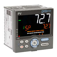
Automationdirect.com prosense PPC5-1001 User Manual (535 pages)
Advanced Process Controllers
Brand:
Automationdirect.com
| Category:
Controller
| Size: 18 MB
Table of Contents
Table of Contents
3
Overview of this Publication
11
Safety Precautions
11
Who Should Read this Manual
11
Checking the Contents of the Package
13
Handling Precautions for the Controller
13
PPC5 Models and Description
14
Symbols Used in this Manual
16
Setup Procedure
17
Chapter 1 - Installation and Wiring
18
Installation Location
19
Mounting Method
21
Mounting the Controller
21
External Dimensions and Panel Cutout Dimensions
22
Mounting the Controller
22
Wiring
23
Important Information on Wiring
23
PV Input Wiring
25
Remote Auxiliary Analog Input Wiring (PPC5-110X Models)
26
Control Output (Relay, Current and Voltage Pulse) Wiring
27
Contact Input Wiring
29
Alarm Contact Output Wiring
31
Retransmission Output Wiring
32
DC Loop Power Supply Wiring
32
Communication Interface Wiring (PPC5-1X01 Models)
33
Coordinated Operation Wiring (PPC5-1X01 Models)
34
Ethernet Communication Interface Wiring (PPC5-1X02 Models)
35
Power Supply Wiring
37
Attaching and Detaching Terminal Cover
38
Chapter 2 - Introduction to Unit, Key, and Display Functions
39
Definition of Main Symbols and Terms
40
Input/Output Function
41
Display and Key Functions
43
Communication Functions
44
Names and Functions of Display Parts
46
Names and Functions of Keys
48
List of Display Symbols
49
Overview of Display Switch and Operation Keys
51
How to Set Parameters
54
Chapter 3 - Quick Setting Function
58
Setting Using Quick Setting Function
59
Restarting Quick Setting Function
64
Chapter 4: Operation Monitoring and Control
65
Monitoring and Control of Operation Displays
66
Operation Display Transitions in Single-Loop Control, Cascade Primary-Loop Control, Cascade Secondary-Loop Control, Loop Control for Backup, and Loop Control with PV-Hold Function
66
Operation Display Transitions in Loop Control with PV Switching and Loop Control with PV Auto-Selector
67
Operation Display Transitions in Loop Control with PV Switching and Loop Control with PV Auto- Selector
67
Operation Display Transitions in Cascade Control
68
Setting Target Setpoint
74
Performing and Canceling Auto-Tuning
76
Adjusting PID Manually
79
Setting Alarm Setpoint
85
Selecting Target Setpoint Number (SPNO)
86
Switching Operation Modes
87
Switching between AUTO and man
87
Switching between cas (Cascade), AUTO, and man
89
Switching between STOP and RUN
91
Switching between REM (Remote) and LCL (Local)
93
Manipulating Control Output During Manual Operation
94
Releasing On-State (Latch) of Alarm Output
96
Chapter 5 - Input Setting Functions
97
Setting Functions of PV Input and Remote Auxiliary Analog Input
98
Setting Input Type, Unit, Range, Scale, and Decimal Point Position
98
Setting Burnout Detection for Input
101
Setting Reference Junction Compensation (RJC) or External Reference Junction Compensation (ERJC)
102
Correcting Input Value
103
Setting Ratio Bias/Filter
108
Setting Input Sampling Period (Control Period)
109
Using Larger, Smaller, Average, or Difference of Two Inputs as PV
110
Setting Remote Input Method
111
Adjusting PV Range for Loop Control with PV Switching or Loop Control with PV Auto-Selector
112
Setting PV Switching Methods of Loop Control with PV Switching
113
Chapter 6 - Control Mode Settings
117
Setting Control Mode (CTLM)
118
Single-Loop Control
118
Cascade Primary-Loop Control
120
Cascade Secondary-Loop Control
122
Cascade Control
124
Loop Control for Backup
126
Loop Control with PV Switching
128
Loop Control with PV Auto-Selector
130
Loop Control with PV-Hold Function
132
Setting Control Type (CNT)
134
PID Control
135
ON/OFF Control (1 Point of Hysteresis / 2 Points of Hysteresis)
136
PD Control (Stable Control in Which a Setpoint Is Not Exceeded)
138
Sample PI Control (Controlling a Process with Long Dead Time)
139
Batch PID Control (Performing Control with Rapidly Settling Setpoints)
141
Setting PID Control Mode (ALG)
143
Switching PID
145
Switching PID According to Target Setpoint Number (SPNO)
145
Switching PID According to PV
146
Switching PID According to SP
148
Switching PID According to Target SP
150
Switching PID According to Deviation (Reference Deviation)
152
Setting Hysteresis at Time of PID Switch
153
Switching PID by Contact Input
153
Suppressing Overshoot (Super Function)
154
Suppressing Hunting (Super2 Function)
156
Suppressing Integral Action (Anti-Reset Wind-Up)
158
Performing Non-Linear PID Control
159
Adjusting Auto-Tuning Operation
160
Chapter 7 - Setpoint Functions
161
Setting SP Limiter
162
Changing SP at a Fixed Rate (SP Ramp-Rate Setting Function)
163
Forcing SP to Track PV (PV Tracking)
165
Forcing SP to Track Remote Input (SP Tracking)
166
Chapter 8 - Output Setting Functions
167
Setting Control Output Type
168
Setting Control Output Cycle Time
170
Setting Limiter to Control Output
171
Disabling Output Limiter in man Mode
172
Setting Velocity Limiter to Control Output
173
Reducing 4-20 Ma Current Output to 0 Ma (Tight Shut Function)
174
Setting ON/OFF Control Hysteresis
175
Canceling Offset of PV and SP (Manual Reset)
177
Setting Retransmission Output Terminal, Type, and Scales
178
Setting Preset Output Value
180
Setting Output Value in STOP Mode (Preset Output)
180
Setting Output Value When Switched to man Mode (Manual Preset Output)
181
Setting Output Value When Error Occurs (Input Error Preset Output)
183
Setting 10-Segment Linearizer for Output
184
Changing Current Output Range
186
Setting Split Computation Output Function
187
Using 15 V DC Loop Power Supply
189
Chapter 9 - Alarm Functions
191
Setting Alarm Type
192
Setting Number of Alarm Groups to Use
204
Setting Hysteresis to Alarm Operation
205
Delaying Alarm Output (Alarm Delay Timer)
206
Setting Alarm Output to Control Relay Terminal
207
Setting Alarm Action According to Operation Mode
208
Chapter 10: Contact Input and Output Functions
209
Setting Contact Input Function
210
Changing Contact Type of Contact Input
220
Setting Contact Output Function
221
Setting Function of Contact Output
221
Changing Contact Type of Contact Output
226
Chapter 11 - Setting Display and Key Functions
227
Setting Display Functions
228
Setting Active Color PV Display Function
228
Masking Arbitrary Display Value in Operation Display
231
Registering SELECT Display (up to 5 Displays)
232
Changing Event Display
233
Registering SELECT Parameter Display (up to 10 Displays)
235
Setting Bar-Graph Display Function
237
Masking Least Significant Digit of PV Display
239
Changing Deviation Display Lamp Action
240
Setting Economy Mode
241
Selecting the Initial Operation Display that Appears at Power on
242
Setting Message Function
243
Switching Guide Display Language
243
Changing Guide Scroll Speed
244
Turning Guide Display ON/OFF
244
Setting Automatic Return to Operation Display
244
Assigning Function to User Function Key and A/M Key
246
Setting Security Functions
249
Setting or Clearing the Password
249
Setting Parameter Display Level
249
Locking (Hiding) Parameter Menu Display
250
Key Lock
252
Setting Display/Non-Display of Operation Display
252
Prohibiting Writing Via Communication
253
Confirmation of Key and I/O Condition and Version
254
Confirmation of Key and I/O Condition
254
Confirmation of Version
257
Chapter 12 - Resetting Default Values
258
Initializing Parameter Settings to Factory Default Values
259
Registering and Initializing User Default Values
260
Registering User Settings as Default Values
260
Initializing to User Setting (Default) Values
260
Chapter 13 - Power Failure Recovery
261
Remedies if Power Failure Occurs During Operations
262
Setting Time between Powering on Controller and Starting Control (Restart Timer)
263
Power Frequency Setting
264
Chapter 14 - Troubleshooting
266
Troubleshooting
266
Troubleshooting Flowchart
266
Maintenance
279
Cleaning
279
Disposal
279
Chapter 15 - Parameter Settings
280
Parameter Map
281
List of Parameters
288
Operation Parameters
288
Setup Parameters
296
Chapter 16: Software Functional Overview
321
Functional Overview
322
Connecting the Controller to a PC and Setting Parameters
324
Chapter 17: Software Setting Flow and Navigation
330
Setting Flow
331
Starting Up/Exiting the Parameter Setting Software
332
Window Names and Functions
334
Creating New Parameter File Using the Wizard Function
337
Setting the Parameter View Level
343
Setting System Data
344
Setting Parameters
347
Creating User File Information
351
Downloading Data
352
Uploading Data
354
Comparing Data with Controller's Data
356
Monitoring/Changing Data
358
Monitoring/Changing Tuning Data
358
Setting Data Read Cycle
369
Managing Files
370
Creating a New File
370
Opening a User File
371
Setting/Clearing a User File Password
372
Closing a File
373
Saving by Overwrite
373
Saving a File
373
Comparing with File Data
374
Saving Tuning Data
375
Saving a CSV File
377
Making Environmental Settings
378
Window Operations
380
Printing
381
Initializing the Controller
382
Checking Software Version
384
Viewing the List of Tables
385
Chapter 18 - Communication Overview
386
PPC5 Controller Communication
387
Communication (PPC5-1X01 Models)
388
Communication Specifications
388
Ethernet Communication (PPC5-1X02 Models)
389
Communication Specifications
389
Coordinated Communication (PPC5-1X01 Models)
391
Communication Specifications
391
Chapter 19 - Communication Settings
392
Setting Parameters
393
Setting RS-485 Communication (PPC5-1X01 Models)
393
Setting Ethernet Communication (PPC5-1X02 Models)
395
Setting Coordinated Operation (PPC5-1X01 Models)
397
Setting Communication Write Permit
398
Chapter 20 - Modbus Communication
399
Modbus Communication (PPC5-1X01 Models)
400
Overview
400
Configuration of Messages
402
Configuration of Responses
406
Specifying Broadcast
407
Messages and Responses
408
Reading Multiple I Relays
409
Reading Multiple D Registers
410
Writing to an I Relay
411
Writing to a D Register
411
Loopback Test
412
Writing to Multiple I Relays
413
Writing to Multiple D Registers
414
Chapter 21 - Modbus/Tcp Communication
415
Overview
416
Overview
417
TCP/IP-Based Communication (PPC5-1X02 Models)
418
Configuration of Network Frames
419
Configuration of MBAP Header
419
Configuration of PDU
419
Communication with Host Computer
420
List of Function Codes
420
Requests and Responses
421
Reading Multiple I Relays
421
Reading Multiple D Registers
421
Writing to an I Relay
422
Writing to a D Register
422
Loopback Test
423
Writing to Multiple I Relays
424
Writing to Multiple D Registers
425
Response Error Codes
426
Ethernet-Serial Gateway Function (PPC5-1X02 Models)
427
Overview
427
Communication with Serial Devices
428
Process Data High-Speed Response Function
429
Overview
429
How to Set the Function
430
Process Data for High-Speed Response
430
IP Access Restriction Function
431
Chapter 22 - Coordinated Operation
432
Overview
433
Coordinated Items
434
Starting Coordinated Operation
435
Chapter 23 - D Registers (Holding Registers)
436
Overview
437
Conventions Used in D Register Tables
438
Classification of D Registers
439
D Registers
439
Process Monitoring
440
10-Segment Linearizer Setting Parameter (D4801 to D5000)
440
Input / Output Terminal Status Register (D7601 to D7700)
440
D Registers
441
Process Monitoring
441
Process Data Area
443
Process Data (D2001 to D2100)
443
Current SP Group and PID Group (D2101 to D2200)
451
Loop-1 Operation Parameter (D2501 to D3600)
452
Loop-1 SP and Alarm Setpoint Setting of Groups 1 to 8 (D2501 to D2700)
459
Loop-1 SP-Related Setting (D2701 to D2800)
460
Loop-1 Alarm Function Setting (D2801 to D2900)
461
Loop-1 PV-Related Setting (D2901 to D3000)
462
Loop-1 PID Setting of Groups 1 to 8 and R (D3001 to D3500)
463
Loop-1 Control Action-Related Setting (D3501 to D3600)
465
Loop-2 Operation Parameter (D3601 to D4700)
466
Loop-2 SP and Alarm Setpoint Setting of Groups 1 to 8 (D3601 to D3800)
472
Loop-2 SP-Related Setting (D3801 to D3900)
473
Loop-2 Alarm Function Setting (D3901 to D4000)
474
Loop-2 PV-Related Setting (D4001 to D4100)
475
Loop-2 PID Setting of Groups 1 to 8 and R (D4101 to D4600)
476
Loop-2 Control Action-Related Setting (D4601 to D4700)
478
P Parameter (D4701 to D4800)
479
10-Segment Linearizer Setting Parameter (D4801 to D5000)
479
Setup Parameters (D5001 to D7000)
482
Control Function Setting (D5001 to D5100)
491
Input Setting (D5101 to D5300)
492
Output Setting (D5301 to D5400)
495
Communication Setting (D5501 to D5700)
498
Key Operation Setting, Display Function Setting, and SELECT Display Setting (D5701 to D5800)
500
Lock Setting (Key Lock/Menu Lock) (D5801 to D5900)
505
DI Function Setting (D5901 to D6200)
507
DO Function Setting (D6201 to D6300)
509
I/O Display (D6301 to D6400)
511
System Setting (D6401 to D6500)
512
Registers (D7001 to D7600)
513
For Input Calculation (D7001 to D7100)
517
For Output Calculation (D7101 to D7200)
518
Status Registers (D7201 to D7300)
518
Constant Register (D7301 to D7330)
520
Input Range / Scale (D7501 to D7600) (Read Only)
520
Input / Output Terminal Status Register (D7601 to D7700)
522
Writing Via Communication
523
Chapter 24 - I Relays (Coil)
524
Overview
525
Classification of I Relays
526
System Error, Input Error, and Operation Mode (4001 to 4320)
531
Alarm, Alarm Latch (4321 to 4576)
531
SP Number and PID Number (4577 to 4704)
532
Key (4705 to 4768)
532
Display, PV Event Status and Time Event Status (4769 to 5024)
532
Advertisement
Advertisement
Related Products
Automationdirect.com prosense PPC5 Series
Automationdirect.com prosense PPC5-1000
Automationdirect.com prosense PPC5-1002
Automationdirect.com prosense PPC5-1100
Automationdirect.com prosense PPC5-1101
Automationdirect.com prosense PPC5-1102
Automationdirect.com CLICK PLUS C2-02CPU
Automationdirect.com P2-08NTC
Automationdirect.com P2-06RTD
Automationdirect.com P2-04AD
Automationdirect.com Categories
I/O Systems
Control Unit
Controller
Temperature Controller
DC Drives
More Automationdirect.com Manuals
Login
Sign In
OR
Sign in with Facebook
Sign in with Google
Upload manual
Upload from disk
Upload from URL