Sign In
Upload
Manuals
Brands
AUKS Manuals
Air Conditioner
ALCA-H18/4DR1
AUKS ALCA-H18/4DR1 Manuals
Manuals and User Guides for AUKS ALCA-H18/4DR1. We have
1
AUKS ALCA-H18/4DR1 manual available for free PDF download: Service Manual
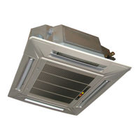
AUKS ALCA-H18/4DR1 Service Manual (162 pages)
DC Inverter 1 Drive 1 50Hz R410a, ALCA-H*4*DR1, ALCA-H*5*DR1 SERIES
Brand:
AUKS
| Category:
Air Conditioner
| Size: 13 MB
Table of Contents
Service Manual
1
Table of Contents
2
Nomenclature
3
Indoor Unit
3
Outdoor Unit
3
Part 1 General Description
3
Unit Appearance
4
Picture of the Indoor Unit
4
Part 2 Indoor Unit
6
Four-Way Cassette
8
Application Occasions
9
Feature
9
Function Introduction
10
Specification
11
Actual Cooling Capacity Calculation
15
Actual Heating Capacity Calculation
15
Capacity Amendment
15
Running Range
15
Correction Capability
16
Different Cooling Capacity Modified Coefficients at Different Height
16
Equivalent Pipe Length Conversion
16
Bend and Oil Loop Conversion Tablet
17
Specification of Connection Pipe for Indoor Unit and Outdoor Unit
17
Dimension
18
Electrical Wiring and Connection
19
Introduction of Control Board Socket
21
Installation
22
Installation Drawing
22
Preparation before Installation
22
Installation Precaution
23
The Distance between Indoor Unit and Obstacle
23
Fixing of Suspension Foundation
24
Indoor Unit Suspension
24
Select the Suspension Foundation
24
Drainage Pipe Installation
25
Connect Duct, Fresh Air Ventilation
26
Panel Installation
26
Explode View
28
Ceiling & Floor Type
34
Feature
35
Capacity Amendment
40
Dimension
43
Electrical Wiring Diagram between Indoor and Outdoor Unit
44
Preparation and Equipments before Installation
47
Explode View
50
Ducted Type Indoor Unit
56
Feature
57
Specfication
59
Capacity Amendment
62
Dimension
65
Electrical Wiring and Connection
66
Fan Performance
69
Installation
71
Installation Diagram
71
Installation Precaution
71
Explode View
75
Part 3 Universal Outdoor Unit
78
Feature
79
Specification
80
Capacity Amendment
83
Dimension
86
Electrical Wiring and Connection
88
Introduction of Control Board Socket (3 Phase)
91
System Diagram
93
Explore View
94
Select Installation Position of Outdoor Unit
100
Maintenance and Ventilation Space
100
Outdoor Unit Installation
100
Transport
100
Piping Connection
101
Piping Specification Selection
101
Piping Installation Precaution
101
Connection Piping Installation
101
Emptying or Vacuum
102
Heat Insulation Package of Piping
103
To Seal the Hole on the Wall
103
Additional Refrigerant Charge
104
Oil Grade and Standard Oil-Filled Volume of Compressor
104
Electrical Connection Precaution
105
Recommendation of Power Supply Cord
105
Power Supply:220V~,50Hz
106
Power Supply 380V~415V 3N,50Hz
106
Wire Connection
106
Outdoor Wire Connection
106
Commissioning
107
Check Installation Condition
107
Check at the Beginning of each Season
108
Clean Inhaler
108
Washing Filter Net
108
Daily Maintenance
108
Part 4 Trouble Shooting
110
Main Components of Air Conditioner
111
Electrical System Main Components
113
Failure Phenomenon
114
Poor Efficiency Explanation
114
Electric Components Malfunction Inspection
115
Failure Code Display
116
Indoor Unit Error Code
116
Outdoor Unit Error Code
116
Failure Analysis
119
Anylisis and Solution for Failure Without Failure Code
119
Wired Controller Communication Failure
119
Communication Failure between Indoor and Outdoor Unit
120
Outdoor Protection(Phase Sequence)
121
Cooling High Pressure Protection
122
Heating High Pressure Protection
123
Cooling Low Pressure Protection
124
Heating Low Pressure Protection
125
Cooling Exhaust Temperature Protection
126
Heating Exhaust Temperature Protection
127
Refrigerant Shortage or Four Way Valve Failure Protection
128
Sensor Failure Protection
129
No Action after Power-On
130
Poor Effect
131
Abnormal Sound or Viberation
133
Abnormal Odor
135
Air Switch Action When Air Conditioner Starting up
136
Air Conditioner Water Leakage
137
Part 5 Controller
138
General Information
139
Remote Controller, Wired Controller, Display Panel and Receiver
139
Basic Condition of Remote Controller
140
Remote Conntroller: L Series
140
Remote Controller
140
“SPEED” Button
140
“Cool”Button
141
“HEALTH” Button
141
“Heat”Button
141
“Swing”Button
141
POWER Button
142
Remote Conntroller: K Series
142
Two White Button
142
“ECO” Button
142
Feeing Button
143
SLEEP Button
143
Timer Setting
143
TIMER/CLOCK Button
143
Basic Condition of Wired Controller
145
ON/OFF Button
145
Wired Controller
145
Wired Controller: XK-02
145
Installation of Wired Controller
146
Timer Button
146
Functional Buttons
147
Mode Button
147
Wired Controller: XK-05
147
Air Speed Button
148
Indicator
148
Other Function
148
Remote Control Receiver
148
Trouble Code Display
149
Wired Controller: XK-01
150
Parameters Setting of Indoor Unit
151
Setting of Indoor Model Based on Remote Controller
151
Setting of Indoor Model Based on Wired Remote Controller
152
Coil Temperature Sensor Resistance Reference Table
154
Part 6 Sensor Resistance Table
154
Environment Temperature Sensor Resistance Reference Table
157
Exhaust Temperature Sensor 6.339K3954
160
Advertisement
Advertisement
Related Products
AUKS ALCA-H24/4DR1
AUKS ALCA-H36/4DR1
AUKS ALCA-H48/5DR1
AUKS ALCA-H60/5DR1
AUKS AL-H18/4DR1(U)
AUKS AL-H36/4DR1(U)
AUKS AL-H24/4DR1(U)
AUKS AL-H60/5DR1(U)
AUKS AL-H48/5DR1(U)
AUKS AFC-800CF/4
AUKS Categories
Air Conditioner
Chiller
Fan
More AUKS Manuals
Login
Sign In
OR
Sign in with Facebook
Sign in with Google
Upload manual
Upload from disk
Upload from URL