Sign In
Upload
Manuals
Brands
attocube Manuals
Controller
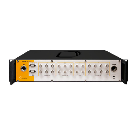
ASC500
attocube ASC500 Manuals
Manuals and User Guides for attocube ASC500. We have
1
attocube ASC500 manual available for free PDF download: User Manual
attocube ASC500 User Manual (123 pages)
SPM Controller
Brand:
attocube
| Category:
Controller
| Size: 7 MB
Table of Contents
Table of Contents
3
Introduction
5
System Overview
5
Safety Information
5
I.2.A. Warnings
6
Declarations of Conformity
8
Waste Electrical and Electronic Equipment (WEEE) Directive
9
Hardware Description
10
II.1. Mechanical Installation
10
II.2. Electrical Installation
11
II.2.A. Connecting to the Voltage Supply
11
II.2.B. Fuses
11
II.3. Front and Rear Panel Connections
12
II.3.A. Front Panel ASC500 V1
12
II.3.B. Rear Panel ASC500 V1
12
II.3.C. Cable Description ASC500 V1
12
II.3.D. Front Panel ASC500 V2
13
II.3.E. Back Panel ASC500 V2
15
II.4. the Ibox
16
III. Description of the Controller
18
III.1. Key Features and Benefits
18
III.2. Hardware Specifications
18
III.3. General Functionality
19
III.4. Hardware Requirements and Operating Systems
20
III.5. Hardware Driver Installation
20
III.5.A. Windows XP
21
III.5.B. Windows Vista / Windows 7 (32/64 Bit)
22
Data Handling
25
IV.1. Quick Guide for Data Saving
25
IV.1.A. the DCC
25
IV.1.B. the Snapshot Preset Configuration
28
IV.2. Data Handling Details
29
IV.2.A. Signals, Data Channels and Data Groups
29
IV.2.B. Internal Signal Flow
29
IV.2.C. Data Processing Chain
30
IV.2.D. Sample Time and Average
31
IV.2.E. Data Channel Configuration (DCC) in Detail
32
IV.2.F. DCC Usage
33
IV.2.G. Saving the Data
34
IV.2.H. Parameter File
38
IV.2.I. Snapshot Presets
38
Operating the Controller: General Usage and Overview
41
V.1. Software Installation and Getting Started
41
V.2. Description of Main Daisy Program
42
V.2.A. the Main Toolbar
42
V.2.B. the Menu Bar
44
V.2.C. Loading a Profile
49
V.3.A. User-Configurable GUI Appearance
51
V.3.B. Aliases Menu
51
V.3. Profile Configuration
51
V.3.C. New Signal and Parameter Names in V2.5
54
V.4. General Usage and Description of Common GUI Controls
55
V.4.A. Text Edit Boxes
55
V.4.B. Context Menu
56
V.4.C. Frame View Context Menu
58
V.4.D. Display Wizard
58
Description of the AFM Profile
62
VI.1. the Output Section
62
VI.2. the Scanner Control
64
VI.2.A. Closed Loop Scanning
67
VI.2.B. Lithography
72
VI.3. the Z Control Feedback Loop
76
VI.4. the Scan Data Displays
78
VI.4.A. Frame View
78
VI.4.B. SCAN Line View Tab
79
VI.4.C. Example for Shifting, Moving and Zooming the Scan Area
81
VI.5. the Main Functions Tab Section
84
VI.5.A. Phase Locked Loop (PLL Tab)
84
VI.5.B. Lever Excitation Tab
91
VI.5.C. the Low Frequency Lock-In Tab (LF Lockin)
92
VI.5.D. Coarse Tab
93
VI.5.E. Pathmode Tab
96
VI.5.F. External Handshake
97
VI.5.G. Dual Pass Mode
99
VI.5.H. Q Control
101
VI.5.I. Crosslink
105
VI.5.J. DAC Outputs
107
VI.5.K. Scan; Manual Positioning
107
VI.6. 1-Dimensional Data Displays
107
VI.6.A. Spectroscopy Tab(S)
107
VI.6.B. Resonance View
109
VI.6.C. Line View
110
VI.6.D. Frequency Analysis View
111
VI.7. Closed Loop Step Scanning
113
VI.7.A. Concept
113
VI.7.B. Connection
115
VI.7.C. Operation
116
VII. Firmware Upgrade
120
VIII. Preventive Maintenance
121
VIII.1. Safety Testing
121
VIII.2. Fuses
121
VIII.3. Cleaning
121
Advertisement
Advertisement
Related Products
attocube ANC300
attocube attoAFM I
attocube ECC100
attocube Categories
Controller
Microscope
More attocube Manuals
Login
Sign In
OR
Sign in with Facebook
Sign in with Google
Upload manual
Upload from disk
Upload from URL