Sign In
Upload
Manuals
Brands
Atop Manuals
Gateway
PG5901B Series
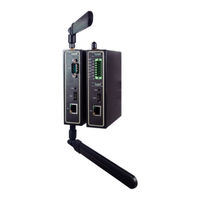
Atop PG5901B Series Manuals
Manuals and User Guides for Atop PG5901B Series. We have
3
Atop PG5901B Series manuals available for free PDF download: Configuration Manual, User Manual
Atop PG5901B Series Configuration Manual (83 pages)
Protocol Gateway
Brand:
Atop
| Category:
Gateway
| Size: 2 MB
Table of Contents
Table of Contents
4
Introduction
7
Scope
7
Overview
7
Document Reference
7
List of Abbreviations
8
General Description
9
Adding the IEC 60870-5-101/104 ADH Application
9
Figure 2-1 - Adding an IEC 60870-5-101/104 ADH Application
9
IEC 60870-5-101 Configuration Guide
10
IEC 60870-5-101 Client Configuration
10
Figure 3-1 - Configuration Settings for the IEC 60870-5-101 Client
10
IEC 60870-5-101 Client Settings
11
Polling Interval (Ms)
11
Link Layer Timeout (Ms)
11
General Interrogation Interval (Ms)
11
Counter Interrogation Interval (Ms)
11
Clock Sync Period (Ms)
12
Command Timeout (Ms)
12
IEC 60870-5-101 Client, Remote IED Tab Layout and Address Settings
13
Link Address
13
ASDU Address
13
Figure 3-2 - Remote IED Configuration Settings for an IEC 60870-5-101 Client
13
IEC 60870-5-101 Remote IED Data Point List
14
Figure 3-3 - Data Point Configuration Options for the IEC 60870-5-101 Client
14
Adding Data Points
15
IEC 60870-5-101 Remote IED Command List
15
Figure 3-4 - Adding Data Points to an IEC 60870-5-101 Remote IED
15
Adding Commands
16
Figure 3-5 - Command Configuration Options for IEC 60870-5-101 Client
16
Figure 3-6 - Adding Commands to an IEC 60870-5-101 ADH Application Client Remote IED
16
IEC 60870-5-101 Remote IED Data Point and Command Parameters
17
Tag
17
Data Type
17
Time Stamp
17
Start IOA
17
Count
17
Operation Mode
18
IEC 60870-5-101 Server Configuration
19
Figure 3-7 - Configuration Settings for a Local IEC 60870-5-101 Server
19
IEC 60870-5-101 Server Settings
20
Link Address
20
ASDU Address
20
Command Timeout (Ms)
20
Positive Acknowledgment
20
Negative Acknowledgment
20
Class 1 Event Buffer Size
21
Class 1 Event Buffer Size over
21
Class 2 Event Buffer Size
21
Class 2 Event Buffer Size over
21
Command Response ACTTERM Used
21
IEC 60870-5-101 Server Tab Layout and Address Settings
22
Figure 3-8 - IED Configuration Settings for IEC 60870-5-101 Server
22
IEC 60870-5-101 Server Data Point and Command Reference List
23
Adding Data Point and Command References
23
Figure 3-10 - Adding Data Point and Command References to an IEC 60780-5-101 Server
24
IEC 60870-5-101 Common Settings
25
Link Address Size
25
ASDU Address Size
25
Information Object Address Size
25
Cause of Transmission Size
25
Data Link Transmission Mode
25
IEC 60870-5-104 Configuration Guide
27
IEC 60870-5-104 Client Configuration
27
Figure 4-1 - Configuration Settings for the IEC 60870-5-104 Client
27
IEC 60870-5-104 Client Settings
28
General Interrogation (Ms)
28
Interrogation for Group X (Ms)
28
Request Counter General for Group X (Ms)
28
Command Timeout (Ms)
28
Interrogation Intervals (Ms)
29
Figure 4-2 - Client Interrogation Intervals
29
IEC 60870-5-104 Client, Remote IED Tab Layout and Address Settings
30
ASDU Address
30
IP Address
30
TCP Port
30
Figure 4-3 - IED Configuration Settings for an IEC 60870-5-104 Client
30
IEC 60870-5-104 Remote IED Data Point List
31
Figure 4-4 - Remote IED Data Point Configuration Options for an IEC 60870-5-104 Client
31
Adding Data Points
32
Figure 4-5 - Adding Data Points to an IEC 60870-5-104 Client
32
IEC 60870-5-104 Remote IED Commands List
33
Figure 4-6 - Command Configuration Options for an IEC 60870-5-104 Client
33
Adding Commands
34
Figure 4-7 - Adding Commands to an IEC 60870-5-104 Client
34
IEC 60870-5-104 Remote IED Data Point and Command Parameters
35
Tag
35
Data Type
35
Time Stamp
35
Start IOA
35
Count
35
Operation Mode
35
IEC 60870-5-104 Server Configuration
37
Figure 4-8 - Server Configuration Settings for the IEC 60870-5-104 Server
37
IEC 60870-5-104 Server Settings
38
ASDU Address
38
Max ADPU Size
38
Event Buffer Size
38
TCP Port
38
Command Timeout (Ms)
38
Limitation of Connections
38
IEC 60870-5-104 Server Tab Layout and Address Settings
39
Figure 4-9 - IED Configuration Settings for an IEC 60870-5-104 Server
39
IEC 60870-5-104 Server Data Point and Command Reference List
40
Adding Data Point and Command References
41
Figure 4-11 - Adding Data Point and Command References to an IEC 60780-5-104 Server
41
IEC 60870-5-104 Common Settings
42
K Value
42
Value
42
T0 Value (S) - Connection Establishment Timeout
42
T1 Value (S) - Send or Test APDU Timeout
42
T2 Value (S) - Acknowledgement Timeout
42
T3 Value (S) - Idle State Test Frame Timeout
43
Clock Sync Period (Ms) (Client Only)
43
Command Response ACTTERM Used (Sever Only)
43
Using Auto-Increment
44
Figure 5-1 - Using Auto Increment When Adding Data Points or Commands
44
IEC 60870-5-101 Interoperability
45
System or Device
45
Network Configuration
45
Physical Layer
45
Link Layer
47
Application Layer
48
Basic Application Functions
54
IEC 60870-5-104 Interoperability
58
Protocol Overview
58
ISO/OSI Model of IEC 60870-5-104
58
Interoperability: IEC 60870-5-104 Client
58
System or Device
59
Link Layer
59
Application Layer
60
Selection of Standard Asdus
61
Basic Application Functions
66
Interoperability: IEC 60870-5-104 Server
70
System or Device
70
Link Layer
70
Application Layer
72
Selection of Standard Asdus
73
Basic Application Functions
78
Advertisement
Atop PG5901B Series User Manual (68 pages)
Protocol Gateway
Brand:
Atop
| Category:
Gateway
| Size: 2 MB
Table of Contents
Table of Contents
4
Introduction
7
Scope
7
Overview
7
List of Abbreviations
7
Getting Started
8
Packing List
8
How to Order
9
First Time Installation
10
Factory Default Settings
10
Configuration and Setup
12
Configuration of Network Parameters through Device View
12
Figure 3-1 - List of Devices on Network in Device Management Utility
12
Figure 3-2 - Pull-Down Menu of Configuration and Network
12
Figure 3-3 - Pop-Up Window of Network Setting
13
Figure 3-4 - Authorization for Changes
13
Configuration through Web Interface
14
Figure 3-5 - Overview Web Page of Protocol Gateway
14
LCM (Liquid Crystal Matrix) Configuration (PG5916 Only)
15
Automatic IP Assignment Configuration with DHCP
17
Web Overview
17
Figure 3-6 - Overview Page
17
Network Configuration
18
Figure 3-7 - Network Configuration Page, Example on PG5900A/08A/16A
18
Link Aggregation
19
Figure 3-8 - Save Completed Page
19
Figure 3-10 - Bonding Settings
19
Virtual IP Settings
20
Figure 3-10 - Bonding Status
20
Figure 3-11 - Virtual IP Settings
20
Protocol Gateway
21
Redundancy Settings
21
Figure 3-12 - Redundancy Settings
21
IEC 61850 IED List - Connection Statistic
22
Advanced Settings
22
SNMP Settings
22
Figure 3-13 - IED Conncetion Statistics
22
Vpn
23
Pptp
23
Figure 3-14 - SNMP Setting
23
Figure 3-15 VPN Scenario of SE/PG/MB 5901B
23
Figure 3-16 PPTP Configuration Page
24
Figure 3-17 PPTP Link Status
24
Ipsec
25
Figure 3-18 an Example of Host-To-Host Connection
25
Figure 3-19 Roadwarrior Application Using Host-To-Subnet Connection
26
Figure 3-20 Gateway Application Using Host-To-Subnet Connection
26
Figure 3-21 an Example of Network Application Using a Subnet-To-Subnet Connection Via the SE59XX and a Peer
26
Device
26
Figure 3-22 an Example of Host-Network Application Via the Subnet-To-Subnet Connection
27
Figure 3-23 an Example of Host-Host Application Via the Subnet-To-Subnet Connection
27
Figure 3-24 Ipsec Tunnels Web Page under Ipsec Setting Menu
28
Table 3.1 Description of Parameters in Ipsec Tunnels Web Page
31
Examples of Ipsec Settings
32
Host-To-Host Connections
33
Figure 3-25 Ipsec VPN Tunnel with Host-To-Host Topology
33
Figure 3-26 General Settings for Host-To-Host with Static Peer
33
Host-To-Network Connections
34
Figure 3-27 General Settings for Host-To-Host with Dynamic Peer
34
Figure 3-28 Ipsec VPN Tunnel with Host-To-Network Topology
34
Figure 3-29 General Settings for Host-To-Network with Static Peer
35
Figure 3-30 General Settings for Host-To-Network with Dynamic Peer
35
Openvpn
36
Openvpn Setting
36
Figure 3-31 Ipsec Link Status
36
Figure 3-32. Openvpn Setting
36
Openvpn Keys
37
Figure 3-33 Openvpn Keys
38
Figure 3-34 Certification Information
39
Figure 3-35 Certificate Upload
39
Openvpn Status
40
Figure 3-36 Openvpn Client Status
40
Figure 3-37 Openvpn Server Status
40
System Setup
41
Time
41
Figure 3-38 - Time Settings Page
41
Security
42
Figure 3-39 - Admin Settings Page
42
Figure 3-40 - Entering the User Name and the New Password
42
Restart
43
Figure 3-41 - Restart Page
43
General Description
44
Protocol Gateway Overview
44
Figure 4-1 - Protocol Gateway Application Example
44
Figure 4-2 - Protocol Gateway Architectural Overview
45
Device Client/Master
46
Device Server/Slave
46
Example - General Settings
47
Example - Polling Process
48
Figure 4-3 - Protocol Gateway Polling Process
48
Example: Command Process
50
Figure 4-4 - Protocol Gateway Command Process
50
Enode Designer Overview
52
Figure 4-5 - Enode Designer Overview
52
Enode Designer User Guide
53
Installation
53
Figure 5-1 - Enode Designer Setup Installer
53
Figure 5-2 - Enode Designer Setup Wizard
53
Main Screen
54
Figure 5-3 - Enode Designer Main Screen
54
Login
55
Figure 5-4 - Splash Screen and Login Window
55
User Administration
56
Creating, Modifying and Removing Users
56
Figure 5-5 - User Administration Principal
56
Figure 5-6 - Access User Administration
56
Defining User Groups
57
Figure 5-7 - Adding a New User
57
Figure 5-8 - Changing a User's User Group
57
Figure 5-9 - Adding a User Group
57
Figure 5-10 - User Group Added
58
Creating a Project
59
Adding a Device (A.k.a. Target Platform or CFE)
59
Figure 5-14 - Adding a Device to the Project
59
Figure 5-15 - Device Added to Project
59
Editing Ethernet Port Properties
60
Editing Communication Port Properties
60
Adding an ADH Application to a Communication Port
60
Figure 5-16 - Network Properties Modified
60
Figure 5-17 - Editing Communication Port Settings Example
60
Figure 5-18 - Add ADH Application to Communication Port Example
61
Figure 5-19 - Choosing Client or Server
61
Figure 5-20 - ADH Application Added to Project
61
Data Points
62
Figure 5-21 - Adding Data Point References
62
Viewing the Database of Data Points
63
Generate and Send Configuration Files
63
Figure 5-23 - Data Point View Window
63
Setting up the FTP Details
64
Send the Configuration
64
Figure 5-24 - Access Device Settings to Set FTP Settings
64
Figure 5-25 - Device Settings Window
64
Figure 5-26 - Send Configuration Files Window
65
Figure 5-27 - Asked to Reboot after Sending Configuration Files
66
Enode Designer Reference Guide
67
Menu Bar Options
67
File
67
Settings
67
Help
67
Tree Menu Options
67
Table 6-1 - Tree Context Menu Options
67
Atop PG5901B Series Configuration Manual (66 pages)
Protocol Gateway DNP3.0 Client/Server
Brand:
Atop
| Category:
Gateway
| Size: 5 MB
Table of Contents
Table of Contents
4
Introduction
6
Scope
6
Document Reference
6
List of Abbreviations
6
General Description
8
Configuration Theory
8
General Screen Description
9
Figure 2-1 - Example Screen
9
DNP3 Configuration Guide
10
Adding the Module in Enode Designer
10
Server IED Properties
10
Figure 3-1 - Adding the Module in Enode Designer
10
Slave Address
11
IP Address
11
IP Port
11
Client Configuration
12
Figure 3-2 - Client Settings Panel (Serial Above; Ethernet Below)
12
Figure 3-3 - Client IED Panel (Ethernet)
12
Client Settings
13
Master Address
13
Communication Medium
13
Link Layer Timeout (Ms)
13
Application Layer Timeout (Ms)
13
Class 0, 1, 2, 3 Poll Interval (Ms)
14
Class 0 Poll Interval (Ms)
14
Adding Data Points
15
Figure 3-4 - Add Data Points Window
15
Servers (Remote Ieds)
16
Figure 3-5 - Multiple Connected Servers Example
16
Figure 3-6 - Add a Connected Server
16
Figure 3-7 - Remove a Connected Server
16
Server Configuration
17
Figure 3-8 - Server Settings Panel Extract
17
Server Settings
18
Master Address
18
Communication Medium
18
Enable Self Address
18
Figure 3-9 - Server IED Panel
18
Class {X} Event Buffer Size
19
Class {X} Event Buffer Overflow Percentage
19
Default Static Variations
19
Default Event Variations
19
Adding Data Point References
21
Figure 3-10 - Add New References Window
21
Figure 3-11 - Data Point References Added
21
Miscellaneous Common
22
Incomplete, Conflicting and Not Needed Information
22
Modify Selected Points Window
23
Figure 3-13 - Modify Data Points Window Example
23
Communication Port Properties
24
Figure 4-1 - Serial Port Properties
24
Figure 4-2 - Ethernet Port Properties
24
Using Auto-Increment Counters
25
Automatic Increments in Constant Values
26
Reference Guide
27
Tag
27
Groups
27
Start Address
27
Count
28
Operation Mode
28
Analog Input Deadband
28
SBO Timeout (Ms)
28
Dnp3'S Related ADH Types
28
DNP3 Client Properties
30
Device Profile
30
Implementation Table
33
DNP3 Server Properties
48
Device Profile
48
Implementation Table
52
Advertisement
Advertisement
Related Products
Atop PG5901 Series
Atop PG5901-X
Atop PG5901B-X
Atop PG5901E-X
Atop PG5904D Series
Atop PG5908A Series
Atop PG5900A
Atop PG5904D-X
Atop PG5908-X
Atop PG5900A-X
Atop Categories
Server
Switch
Gateway
Wireless Access Point
I/O Systems
More Atop Manuals
Login
Sign In
OR
Sign in with Facebook
Sign in with Google
Upload manual
Upload from disk
Upload from URL