Sign In
Upload
Manuals
Brands
Atmos Manuals
Control Systems
ACD 04
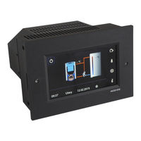
User Manuals: Atmos ACD 04 Equithermal Control Set
Manuals and User Guides for Atmos ACD 04 Equithermal Control Set. We have
1
Atmos ACD 04 Equithermal Control Set manual available for free PDF download: Operation Manual
Atmos ACD 04 Operation Manual (292 pages)
Brand:
Atmos
| Category:
Control Systems
| Size: 14 MB
Table of Contents
Hydraulic Diagram: 11033 Example
1
Table of Contents
3
Atmos Acd
3
Atmos Acd
4
Software Version
9
Introduction
9
Description
10
Basic Division of ATMOS ACD 03 and ATMOS ACD 04 Controllers
10
Variants of ATMOS ACD 03 and ATMOS ACD 04 Controllers
11
ATMOS ACD 03 - Controller Inserted into Boiler Panel
11
ATMOS ACD 04 - ATMOS ACD 04 - Controller Installed in Boiler Instrument Hood (in Factory)
11
Installation in Boiler
13
Hydraulic Diagram: 63033 Example
13
Hydraulic Diagram: 67833 Example
14
Recommended Sensors Installation
15
Connection
17
Connection Terminals (Description) on the Back Side of the Controller
17
Terminal Block and Connectors
17
Overview of Connection Terminals of ACD 03/04 Controller
18
INSTALLATION GUIDE (WIZARD) (First Start of the Controller)
20
Installation Guide
20
Hydraulic Diagram: 27533 Example
20
Hydraulic Diagram: 27533 Example
21
Key to Define Hydraulic Diagram Number
25
Buttons and Information on the Screen
27
ATMOS ACD 03/04 Controller Display
27
Operating Modes Menu
46
Basic Description of Operating Modes
48
Standby - Permanent Working Mode
49
Setback - Permanent Working Mode
50
Comfort - Permanent Working Mode
51
Summer - Permanent Working Mode
52
Auto (Time Program) - Permanent Working Mode
53
Visit - Temporary Working Mode
55
Absence - Temporary Working Mode
56
Holidays - Temporary Working Mode
57
Temperature Setting Menu
58
10. Setting Menu
59
Date, Time
60
Setting the Current Time
60
Setting the Current Date
60
Setting Automatic Switching to Summer Time
61
Time Calibration Setting (Seconds/Week)
61
The Function Allows You to Set the Time Measurement Deviation Setting (Number of Seconds Per Week)
61
Time Source
62
Time Programs for Auto Mode
63
Weekly Program Selection (Week a / Week A, B, C)
64
Time Programs Setting
65
Weekly Time Program Overview
66
Daily Time Program Overview
66
Copying the Day
68
Copying Weekly Heating Circuit Program
69
Limitations (Link to Other Parameters)
70
Resetting Time Programs to Their Default State
71
Hydraulics
72
Menu - Hydraulic Diagram Overview
72
Menu - Communication
76
Menu - Function Configuration
85
Terminal Assignment
86
Terminal Change
88
Release the Clamp
89
Boiler Type Designation
90
Controlled Boiler
90
Boiler Submenu- Definition of Additional Functions for the Boiler
91
Accumulation Tank Submenu- Overview of Defined Elements
96
Domestic Water DHW (2) Submenu - Overview of Defined Elements
99
Heating Circuit 1 Function Submenu
105
Heating Circuit 2 Function Submenu
112
Heating Circuit 3 Function Submenu
119
Heating Circuit 4 Function Submenu
126
Sources Submenu
127
Solar Heating Submenu
131
General Setting Submenu - Definition of Additional Functions
133
Temperature Sensors Submenu - Definition of Additional Sensors
135
Menu - Output Test
137
Menu - Actuator Direction of Rotation
138
Hydraulic Diagram
139
Key to Define Hydraulic Diagram Number
140
Overview of Connection Terminals of ACD 03/04 Controller
142
Examples of Hydraulic Diagrams
144
Not Controlled Boiler Connected Without Accumulation Tank
144
Not Controlled Boiler Connected with Accumulation Tanks
146
Controlled Boiler Connected Without Accumulation Tank
148
Controlled Boiler Connected Without Accumulation Tank
150
Controlled Boiler Connected with Accumulation Tanks
152
Controlled Boiler (GSE) Connected with Accumulation Tank
154
Controlled Boiler (GSE) Connected with Accumulation Tank
156
Controlled Boiler (GSE) Connected with Accumulation Tanks (into Series)
158
Controlled Boiler with Burner Connected Without Accumulation (Buffer) Tank
160
Controlled Boiler with Burner Connected with Accumulation (Buffer) Tank
162
Controlled Boiler with Burner Connected Without Accumulation (Buffer) Tank
164
Hydraulic Diagram: 23033 Example11
165
Controlled Boiler with Burner Connected with Accumulation (Buffer) Tank
166
Controlled Combined Boiler (with Modification for Burner) Connected Without Accumulation Tank
168
Controlled Combined Boiler (with Modification for Burner) Connected with Accumulation Tank
170
Controlled Combined Boiler (SP) Connected Without Accumulation Tank
172
Not Controlled Combined Boiler (SP) Connected with Accumulation (Buffer) Tank
174
Controlled Combined Boiler (SP) Connected with Accumulation Tanks (Parallel)
176
Controlled Combined Boiler (GSP) Connected with Accumulation Tanks (into Series)
178
Controlled Boiler Connected with Accumulation Tank and Solar System
180
Controlled Boiler with Burner Connected with Accumulation (Buffer) Tank and Solar System
182
Controlled Boiler with Burner Connected with Accumulation (Buffer) Tank and Solar System
184
Controlled Boiler Connected with Accumulation Tank and External Boiler Without Built-In Pump
186
Controlled Boiler Connected with Accumulation Tank and Heat Pump
188
System
190
Boiler
200
Automatic Wood Ignition
210
Accumulation Tank
216
Sources
221
Heating Circuit 1 / 2 / 3
225
Dhw
236
General Function
242
Solar Heating
243
Sensors Calibration
250
Sweeper
251
Alarms
253
Alarm Overview
254
Password
256
Advertisement
Advertisement
Related Products
Atmos ACD 03
Atmos AC32
Atmos A70 Petro
Atmos Aqua clean
Atmos A85
Atmos A 161 Battery DDS
Atmos A 161
Atmos A 261
Atmos A45
Atmos A25
Atmos Categories
Medical Equipment
Boiler
Air Compressor
Indoor Furnishing
Burner
More Atmos Manuals
Login
Sign In
OR
Sign in with Facebook
Sign in with Google
Upload manual
Upload from disk
Upload from URL