Table of Contents
Advertisement
Advertisement
Table of Contents

Related Manuals for Atmos ACD 04

Summary of Contents for Atmos ACD 04
-
Page 1: Hydraulic Diagram: 11033 Example
Operation manual - EN ACD03/04 Operation manual www.atmos.eu EN - 1... - Page 2 Operation manual - EN ACD03/04 www.atmos.eu...
-
Page 3: Table Of Contents
Variants of ATMOS ACD 03 and ATMOS ACD 04 controllers ATMOS ACD 03 - Controller inserted into boiler panel ATMOS ACD 04 - ATMOS ACD 04 - Controller installed in boiler instrument hood (in factory) 11 4. INSTALLATION IN BOILER... -
Page 4: Atmos Acd
Menu - Output test: Menu - Actuator direction of rotation: Hydraulic diagram Key to define hydraulic diagram number Overview of connection terminals of ACD 03/04 controller Examples of hydraulic diagrams: Not controlled boiler connected without accumulation tank Hydraulic diagram: 11033 Example 1... - Page 5 Controlled boiler connected with accumulation tank and heat pump Hydraulic diagram: 37003 Example 23 Parameters: System Boiler Automatic wood ignition Accumulation tank Sources Heating circuit 1 / 2 / 3 / (4) General function Solar heating Sensors calibration Sweeper Alarms Alarm overview Password www.atmos.eu EN - 5...
- Page 6 HEATING CIRCUIT 1 / 2 / 3 / (4) menu DHW menu SOURCES menu GENERAL FUNCTION menu SOLAR HEATING menu 13. ROOM UNITS ARU5 Room unit (sensor) ARU10 Room unit with temperature correction ARU30 Room unit with touch screen 14. TECHNICAL PARAMETERS GARANTIEBEDINGUNGEN www.atmos.eu EN - 6...
- Page 7 Accumulation tank Sources Heating circuit 1 / 2 / 3 / (4) General function Solar heating Sensors calibration Sweeper Alarms Password 11. INFORMATION MENU 12. OVERVIEW OF MENUS AND THEIR PARAMETERS 13. ROOM UNITS 14. TECHNICAL PARAMETERS www.atmos.eu EN - 7...
- Page 8 Operation manual - EN ACD03/04 www.atmos.eu EN - 8...
-
Page 9: Software Version
System information. 2. INTRODUCTION Equithermal controllers ATMOS ACD 03 and ATMOS ACD 04 with touch screen are designed for comfortable control of the hot-water system of the heated building. The control of the controller is very simple and intuitive thanks to the touch screen. -
Page 10: Description
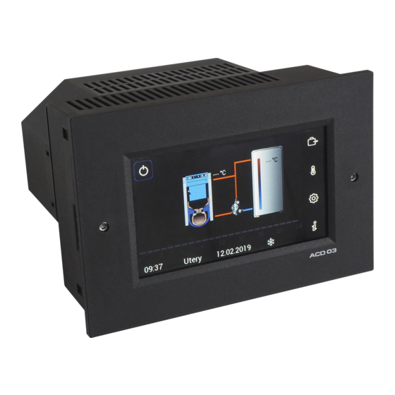
ATMOS ACD 03 ATMOS ACD 04 1 - Screw for the attachment of the ACD 03 controller to the boiler panel 2 - Touch screen 3 - Openings for attachment of the ACD 04 regulator in the boiler instrument hood... -
Page 11: Variants Of Atmos Acd 03 And Atmos Acd 04 Controllers
The control functions of both controllers are the same. ATMOS ACD 03 - Controller inserted into boiler panel The ACD 03 controller is designed to be inserted into the boiler panel after breaking out the readyprepared opening (factory prepared) for ACD 03 controller (dimension 92 x 138 mm). - Page 12 03/04-B relay module. The module is designed to control individual power parts of the heating sys- tem such as pumps, actuators, etc.. On the back of the controller there are connectors for sensors (ATMOS ACD 03A / ACD 04) and power parts (ACD 03/04-B).
-
Page 13: Installation In Boiler
Operation manual - EN ACD03/04 4. INSTALLATION IN BOILER ATMOS ACD 03 Breaking the opening and installation of the regulator into the ATMOS boiler hood panel. Break the opening by hand Broken opening (92 x 138 mm) Example of the connection of individual... -
Page 14: Hydraulic Diagram: 67833 Example
ATMOS ACD 04 Installation / removal of the ACD 04 controller into / from the boiler hood. Special ATMOS instrument hood for ACD 04 controller with four M4 screws. Installation of the controller on four M4 screws Attention - do not overtighten (right-hand... -
Page 15: Recommended Sensors Installation
The AGF flue gas sensor attached to the boiler flue gas duct with tube heat exchanger (DCxxGSE, DCxxGSX, DCxxDG), the sensor is added to the flue gas thermostat capillary of the original electromechanical regulation of the boiler. This sensor must be covered with insulation!!! www.atmos.eu EN - 15... - Page 16 It is not recommended to place (attach) the sensor on the pipe due to the proper functioning of the controller!!! Additional sensor behind the mixing valve measuring the temperature of water flowing into the heating circuit. www.atmos.eu EN - 16...
-
Page 17: Connection
Terminal block and connectors View of controller with connectors Upper connectors for power parts sn: 1135 Lower connectors for sensors Example of wiring Attention - connectors are equipped with pins preventing them from being misplaced on the terminal block www.atmos.eu EN - 17... -
Page 18: Overview Of Connection Terminals Of Acd 03/04 Controller
Operation manual - EN ACD03/04 Overview of connection terminals of ACD 03/04 controller Terminal Abbreviation Terminal name - Description - Special INPUT INPUT Log. Sensor type, note fan speed sensing (special function) input Terminal Abbreviation Terminal name - Description - Special OUTPUTS OUTPUTS Log. - Page 19 L-FAN output phase (L-FAN OUT) 230 V / 50 Hz output Connected to the CU INFO - We recommend leading the sensor and communication cables separately from 230 V conductors and other power lines (at least 5 cm). www.atmos.eu EN - 19...
-
Page 20: Installation Guide (Wizard) (First Start Of The Controller)
For new installation, select NO When replacing the controller (to upload backup), select YES (confirm with the green arrow in the upper right corner) (use the red arrow in the upper left corner to return to the previous setting) www.atmos.eu EN - 20... -
Page 21: Hydraulic Diagram: 27533 Example
(use the red arrow in the upper left corner to return to the previous setting) Do you want the ATMOS ACD 03/04 controller to also control the boiler itself (fan, burner, air flap, etc.)? If yes, , an AGF combustion product temperature sensor must be installed in boilers with manual stoking (combustion gas duct temperature). - Page 22 (boiler (heating) circuit equipped with an accumulation tank with temperature sensor(s) and domestic water heating controlled by controller and boiler pump) ATTENTION - Devices (DKP, DHW, ACC) that are not defined cannot be controlled by ACD 03/04 controller. www.atmos.eu EN - 22...
- Page 23 3 with regard to variable use of circuit outputs and possible collisions with other circuits (outputs). The heating circuit can be controlled using the room units when setting the output functions to DK, MK, KR, FR, DHW2. www.atmos.eu EN - 23...
- Page 24 7 - FR ..mixed fixed (heating circuit control to constant temperature without source (boiler) temperature demand)) 8 - RLA .. mixed back into the boiler (heating circuit defined to monitor the return water to the boiler (return control)) www.atmos.eu EN - 24...
-
Page 25: Key To Define Hydraulic Diagram Number
(adjust) the required function for the boiler and the mixed (heating) circuit. If the manually defined function does not correspond to any function (number) in the key (table) of the hydraulic diagram, the number 9 is automatically entered in the hydraulic diagram number. www.atmos.eu EN - 25... - Page 26 Info - after saving the setting, the main screen of your chosen hydraulic diagram appears on the display. Check everything again and perform the Relay Test (outputs test - pumps, mixing valves, boiler, etc.). If everything is OK you can put the boiler in operation. www.atmos.eu EN - 26...
-
Page 27: Buttons And Information On The Screen
Operation manual - EN ACD03/04 7. BUTTONS AND INFORMATION ON THE SCREEN ATMOS ACD 03/04 controller display - exhaust fan start button (off / source switch) - source (boiler) - indicates the boiler fan operation (on = rotates / off = symbol is not displayed) - Page 28 - Used to move in the menu vertically, if you do not use the features of the touch screen - Used to move in the menu horizontally, if you do not use the features of the touch screen www.atmos.eu EN - 28...
- Page 29 - used to delete the entered character value (Backspace) - used to switch to the numeric keypad screen - used to switch to the screen with a sliding gesture - used to change the size of the step (sensitivity) www.atmos.eu EN - 29...
- Page 30 Boilers with manual stoking - button for shutdown of the PRESS pressure fan for a limited time (3 min. (using → P09 Parameter)) when operating the boiler Boiler and when adding fuel or removing ash - short click. www.atmos.eu EN - 30...
- Page 31 INFO - if the burner is manually switched off (disabled) ( - symbol is red), the alarm of the switched off burner is displayed on the Information button and the "BRE blocked" information is displayed inside! www.atmos.eu EN - 31...
- Page 32 - Symbol light turns red (operation disabled) → short click → - symbol light turns green (operation enabled) ATTENTION - Do not connect the burner power connector until the burner has been completely installed in the boiler. www.atmos.eu EN - 32...
- Page 33 - Symbol light turns red (operation disabled) → short click → - symbol light turns green (operation enabled) ATTENTION - Do not connect the burner power connector until the burner has been completely installed in the boiler. www.atmos.eu EN - 33...
- Page 34 If the boiler (BRE burner) is not in operation (burner STOPped), the source is switched immediately and the burner can be safely removed from the boiler and stoking can be performed (manually). www.atmos.eu EN - 34...
- Page 35 Parameter - 2-BRE+time (boiler fan switches off with delay according to the Boiler → P24 time set in Parameter) Boiler ATTENTION - When removing the burner from the boiler, always disconnect the connector for its power supply. www.atmos.eu EN - 35...
- Page 36 If the boiler is not in operation (not burning), the flue gas temperature is lower than the AGFmin minimum flue gas temperature defined by → Parameter, the source will be switched Boiler immediately and in case of heating system demand the burner is switched on (started). www.atmos.eu EN - 36...
- Page 37 → P18 Parameter, the hand symbol button will flash and Boiler the switching on to burner is performed after burnout of the boiler. If there is a heating system requirement, the burner is switched on (started). www.atmos.eu EN - 37...
- Page 38 INFO - If the burner was previously disabled ( - the symbol is lit in red), then its operation will remain disabled even after switching the source. ATTENTION - In order to start the burner (BRE), the limit switch on the boiler hood must be pressed (blue button next to the upper door). www.atmos.eu EN - 38...
- Page 39 3 seconds. If the boiler (BRE burner) is not in operation (burner STOPped), you can safely open the upper door of the boiler for (manual) stoking. www.atmos.eu EN - 39...
- Page 40 → P18 Parameter, the source is switched and the button Boiler with the hand symbol is displayed. After that, you can safely open the upper door of the boiler for (manual) stoking. www.atmos.eu EN - 40...
- Page 41 Parameter – OFF – boiler exhaust fan does not run during burner operation. Boiler INFO - If you turn the burner off during its operation (disable its operation), then its operation will remain disabled even after switching from manual heating (stoking) to automatic operation with burner. www.atmos.eu EN - 41...
- Page 42 Select the method how the automatic wood ignition should be switched on. Choose from three basic options: Time plan (according to the time program) System requirement (for installation without accumulation tanks) Accumulation temperature (according to the discharge (of temperature) of the accumulation tank) www.atmos.eu EN - 42...
- Page 43 Ignition start delay of the fuel ignition (0–72 hours). INFO – When the boiler is installed without an accumulation tank, the item is not active (not visible). www.atmos.eu EN - 43...
- Page 44 When the automatic ignition of wood is started, the boiler exhaust fan and the ignition spiral are tur- ned on. Everything is indicated by the flashing of the automatic ignition symbol next to the hand symbol button www.atmos.eu EN - 44...
- Page 45 → Parameter → ), the boiler will be shut down after the ignition time has elapsed (60 min - Boiler Parameter P08 ). Information about a failed ignition is displayed in Information – Wood Boiler ignition failed! www.atmos.eu EN - 45...
-
Page 46: Operating Modes Menu
Operating modes menu is used to set individual functions and temperatures for defined circuits. Before setting the selected mode, select the (heating) circuit for which the mode is to be set. Circuits without connection (Summer mode not active) Circuits with connection (Summer mode active) www.atmos.eu EN - 46... - Page 47 Temporary modes Holiday │ Absence │ Visit INFO - After touching the required mode, the modes (Auto │ Summer │ Comfort │ Setback │ Standby ) will be automatically set. www.atmos.eu EN - 47...
-
Page 48: Basic Description Of Operating Modes
, it is necessary to set the mode period (days), for which the room unit shall remain in that mode. INFO - Temporary modes are most often used as a non-recurring change, after which the system returns to Auto mode www.atmos.eu EN - 48... -
Page 49: Standby - Permanent Working Mode
Only the room frost protection remains active ( → Parameter = 8,0 °C) Heating circuit INFO - The Information for the heating circuit shows the current and required room temperature or DHW temperature (if detected) and the working mode. Example setting www.atmos.eu EN - 49... -
Page 50: Setback - Permanent Working Mode
(including heating of DHW). INFO - The Information for the heating circuit shows the current and required room temperature or DHW temperature (if detected) and the working mode. Example setting www.atmos.eu EN - 50... -
Page 51: Comfort - Permanent Working Mode
(including heating of DHW). INFO - The Information for the heating circuit shows the current and required room temperature or DHW temperature (if detected) and the working mode. Example setting www.atmos.eu EN - 51... -
Page 52: Summer - Permanent Working Mode
(domestic water) DHW is required. INFO - The Information for the heating circuit shows the current and required room temperature or DHW temperature (if detected) and the working mode. Example setting www.atmos.eu EN - 52... -
Page 53: Auto (Time Program) - Permanent Working Mode
INFO - The Information for the heating circuit shows the current and required room temperature or DHW temperature (if detected) and the working mode. Example setting Auto (time program) - one-week mode A www.atmos.eu EN - 53... - Page 54 Operation manual - EN ACD03/04 Example setting Auto (time program) - three-week mode A - B - C www.atmos.eu EN - 54...
-
Page 55: Visit - Temporary Working Mode
INFO - INFO - The Information for the circuit shows the current and required room temperature or DHW temperature (if detected), current date and time, time of the end of the working mode and the working mode. Example setting www.atmos.eu EN - 55... -
Page 56: Absence - Temporary Working Mode
INFO - INFO - The Information for the circuit shows the current and required room temperature or DHW temperature (if detected), current date and time, time of the end of the working mode and the working mode. Example setting www.atmos.eu EN - 56... -
Page 57: Holidays - Temporary Working Mode
INFO - INFO - The Information for the circuit shows the current and required room temperature or DHW temperature (if detected), current date and time, time of the end of the working mode and the working mode. Example setting www.atmos.eu EN - 57... -
Page 58: Temperature Setting Menu
4 - Current temperature (measured) 2 - required economic (setback) temperature ( ) 5 - Gesture / arrow setting 3 - current working mode 6 - Sensitivity (step) switching - 0.1 / 0.5 Example of the correct setting procedure www.atmos.eu EN - 58... -
Page 59: 10. Setting Menu
– offset of individual sensors Sweeper – special functions for adjustment and measurement of the combustion source Alarmy – list (index) of the latest alarms Password – allows access to the service interface - service technician / manufacture www.atmos.eu EN - 59... -
Page 60: Date, Time
Operation manual - EN ACD03/04 Date, Time (Access level - User) The setting is performed with the button (to enter the menu), then click on the symbol for Date and time. Setting the current time Setting the current date www.atmos.eu EN - 60... -
Page 61: Setting Automatic Switching To Summer Time
The function allows you to set the time measurement deviation setting (number of seconds per week). INFO - The controller works with real time, which may be delayed or accelerated due to the environment. By setting the incremental value, the time continually adjusts automatically. www.atmos.eu EN - 61... -
Page 62: Time Source
ACD03/04 Time source The function is used to select the time source (controller ACD 03/04 or ARU30 room unit) according to which the other connected devices will be synchronized. As the best time source, we recommend always using a selected and paired ARU30 room unit, which has the least time distortion (deceleration or acceleration) due to the surrounding temperature. -
Page 63: Time Programs For Auto Mode
Control circuit. The dependent heating circuit(s) take(s) over all requirements and modes from the Control circuit ( → Hydraulics / Function Configuration / Circuit Connection Type = Dependent). Control circuit connection setting: www.atmos.eu EN - 63... -
Page 64: Weekly Program Selection (Week A / Week A, B, C)
(morning - afternoon - night), where the user uses different time of day every week, or for holidays, where e.g. week A is set as standard normal week and week B is set for all-day heating to a comfortable temperature, etc. www.atmos.eu EN - 64... -
Page 65: Time Programs Setting
Operation manual - EN ACD03/04 Time programs setting After clicking on the displayed block or editing tool, it is possible to define individual blocks of comfort temperature of the relevant day. www.atmos.eu EN - 65... -
Page 66: Weekly Time Program Overview
Use the arrows on the toolbar or the horizontal gesture to scroll the screen throughout the day to view individual blocks. Use the arrows next to the relevant day in the status bar to switch the days within the selected week. www.atmos.eu EN - 66... - Page 67 Add tool, it is possible to add another block to the day being edited, the maximum number of comfort temperature blocks is 5. INFO - If the time block is short, the set temperature and time range are not displayed. Deleting time block: Use the Delete tool to remove the selected block. www.atmos.eu EN - 67...
-
Page 68: Copying The Day
Copying the day After clicking on the Copy tool, the displayed day can be copied to other days of the week; the selected day is highlighted, the selection is canceled after the next click. www.atmos.eu EN - 68... -
Page 69: Copying Weekly Heating Circuit Program
For a faster definition, the entire heating circuit time program can be simply copied to another heating circuit or DHW. INFO - If no heating circuit is selected, you cannot exit the screen by pressing the OK button. www.atmos.eu EN - 69... -
Page 70: Limitations (Link To Other Parameters)
The temperature set under the Comfort button (Comfort temperature) of the daytime temperature is maintained, which means that the comfort temperature is the same in all blocks. www.atmos.eu EN - 70... -
Page 71: Resetting Time Programs To Their Default State
Operation manual - EN ACD03/04 Resetting time programs to their default state If necessary, you can return the current time program setting to the original factory setting using the tool - Reset time programs to the default state. www.atmos.eu EN - 71... -
Page 72: Hydraulics
It is used to display the complete overview of defined parameters of the heating system, which the controller controls. This is the same overview that is displayed in the last step of the Installation Guide (Wizard): Function configuration menu is used to change (correct) defined functions in the Installation Guide. www.atmos.eu EN - 72... - Page 73 → Hydraulics/Function configu- ration/Boiler/AGF - boiler flue gas temperature. Burner type designation (e.g. A25) - the button (active row) allows you to select a different type of burner from the list. www.atmos.eu EN - 73...
- Page 74 Function configuration menu, if necessary. Each sensor or output is listed as a function. For example, if the sensor is connected, the AGF flue gas temperature value is displayed for easy terminal check and designation Information group - Boiler pump www.atmos.eu EN - 74...
- Page 75 Information group - Domestic water Information group - Heating circuit 1 / 2 / 3 / 4 function (if activated) Information group - Temperatures INFO - Changes to these functions are performed with the Function configuration button (menu). www.atmos.eu EN - 75...
-
Page 76: Menu - Communication
Hydraulics/Communication (Access level - User - nothing / Service technician - everything) The Communication menu is used to pair and set individual room units (devices) with the ACD 03/04 controller. The controller allows the definition (setting) of up to 5 ARUa, ARUb, ARUc, ARUd and ARUe units (Circuit 1, 2, 3 and 4 and DHW). - Page 77 Pairing can be performed in several ways depending on the type of device. Pairing from the ACD 03/04 controller by entering the address On the ACD 03/04 controller, go back one step in the menu by clicking on the symbol and click on (select) the activated unit, for example ARUa (b, c, d, e).
- Page 78 (device), e.g. 0009. This will automatically pair the room unit (device) with the ACD 03/04 controller, which is indicated, for example, on the ARU10 room unit by LED signaling change, displaying the currently set working mode.
- Page 79 Operation manual - EN ACD03/04 On the ACD 03/04 controller, go back one step in the menu by clicking on the symbol and click on (select) the activated unit, for example ARUa (b, c, d, e). Click the Pairing button and go to the room unit or selected device that is to be paired (time limit to pair is 300 s (5 minutes)).
- Page 80 - the pairing of the ARU30 room unit with the ACD03/04 controller is confirmed by the display communication on display. The pairing on the ACD 03/04 controller with the ARU10 and ARU30 room unit is confirmed by the "Paired" inscription (by terminating the time countdown before it expires).
- Page 81 (select) the activated unit, for example ARUa (b, c, d, e). Click the Pairing button (time limit to pair is 300 s (5 minutes)). The pairing on the ACD 03/04 controller with the ARU30 room unit is confirmed by the "Paired" inscription (by terminating the time countdown before it expires).
- Page 82 ATTENTION - Each device (ARU10, ARU30, other devices) is slightly different, so it requires a different pairing procedure! INFO - The pairing process can be interrupted on the ACD 03/04 controller ( → Hydraulics / Communication) by clicking the Pairing button again (the time countdown disappears).
- Page 83 For the ARU30 room unit, it is possible to select more circuits under the Controlled circuit button, which will be displayed on the room unit display and for which we can change the required room temperatures (Comfort temperature , Setback temperature ). www.atmos.eu EN - 83...
- Page 84 The name of the room unit (sensor) is then displayed in the controller in Information (Group - External sensors). ARU30 room unit name is also displayed when selecting the time source → Date and time/Time source. www.atmos.eu EN - 84...
-
Page 85: Menu - Function Configuration
INFO - Corresponding sensors must be connected for the individual functions of the controller. Sensors are connected to free inputs, ideally according to the manufacturer's (controller) recommendations. ATTENTION - Always make changes after careful consideration to prevent the system from collapsing! www.atmos.eu EN - 85... -
Page 86: Terminal Assignment
INFO - An undefined function (unassigned terminal (input - sensor) / (output - device)) is displayed with an warning sign, which indicates that it is not active. www.atmos.eu EN - 86... - Page 87 E.g.: Terminal assignment - output - when adding electric heating of EHP accu tank. After pressing the selected output, for example the EHP - electric heating of accu tank, select the free terminal VA1, to which the required device shall be connected, and confirm. www.atmos.eu EN - 87...
-
Page 88: Terminal Change
If you reset the original hydraulic diagram number, the sensors or outputs are redefined (returned) to the original terminals. Therefore, make changes with the utmost caution! www.atmos.eu EN - 88... -
Page 89: Release The Clamp
We use the function most often in the case of fully occupied terminals, when the terminal cannot just be switched (changed) to another. INFO - An undefined function (unassigned terminal (input - sensor) / (output - device)) is displayed with an warning sign, which indicates that it is not active. www.atmos.eu EN - 89... -
Page 90: Boiler Type Designation
→ Hydraulics/Hydraulic diagram overview/ Boiler type designation. Controlled boiler - (Yes / No) - the button is not active (information only). INFO - To change the function go to → Hydraulics/Hydraulic diagram overview/ Controlled boiler menu. www.atmos.eu EN - 90... -
Page 91: Boiler Submenu- Definition Of Additional Functions For The Boiler
FAN – exhaust boiler fan - the function is based on the boiler type set in the Installation Guide (Wizard). As standard, it is the exhaust boiler fan that removes the flue gases from the boiler. However, some boilers use a PRESS pressure fan (e.g. ATMOS DC100, DC70S), see the following functions. - Page 92 INFO - The logic of the burner control according to the sensors in the PF accumulation tank (upper) and FPF accumulation tank (lower) is the same as for the ATMOS pellet burners, the control according to the TV sensor (upper) and TS sensor (lower). The temperature is not set up, it is automatically calculated according to the requirements of the heating system.
- Page 93 (hand symbol) of the ACD03/04 controller. It disables or enables burner (BRE) operation. For a boiler with a fan (type 3, 4, 5 - FAN or PRESS), pressing the external button shall call up www.atmos.eu EN - 93...
- Page 94 VI1 (17) SF (7) (KVLF) Max. 60°C PLP output type - NC - zone valve without electric current closed VI2 (19) (KSPF) ATMOS SLP (62) MKP1 (53) MKP2 (56) VA3 (37) (SOLP) MK1 (40,41) MK2 (43,44) 2 - 6 bar 10 - 15 °C...
- Page 95 / in OFF states – open terminals. - SAIH – switching contact for AIW (for terminals – DVI1, DVI2) – allows remote control by any device (GSM, WiFi – voltage 230 V / 50 Hz). In ON / OFF mode. www.atmos.eu EN - 95...
-
Page 96: Accumulation Tank Submenu- Overview Of Defined Elements
ARU10 ARU30 22,5 °c ARU5 (31-34) by P18 parameter. Accumulation tank (31-34) VF2 (11) Max. 60 °C Max. 50°C SF (7) VF1 (9) ATMOS AF (4) Additional functions can be defined in the Accumulation tank submenu: www.atmos.eu EN - 96... - Page 97 Electric heating (heating cartridge, heat pump) is switched off when the DKP pump is Max. 50°C switched on (the boiler is switched on). ARU30 22,5 °c Max 60 °C MKP1 MKP2 ATMOS MKP1 ATMOS Max. 60 °C 2 - 6 bar 10 – 15 °C SFINT 2 - 6 bar 10 - 15 °C...
- Page 98 Max. 50°C SF (7) VF1 (9) ATMOS AF (4) ATTENTION - in case of addition of a new sensor to the accumulation tank, it is necessary to assign a specific terminal (location) to the function, where the function is connected.
-
Page 99: Domestic Water Dhw (2) Submenu - Overview Of Defined Elements
SF2 sensor - DHW 2nd tank sensor (NTC sensor 20 kΩ) - temperature required to control the heating of the domestic hot water tank (DHW). Installation of the sensor in the middle or in the upper half of the domestic hot water tank (DHW boiler). www.atmos.eu EN - 99... - Page 100 Next, go a step back by clicking on the symbol and set - Circuit connection type. INFO - With regard to the simplicity of operation, we always recommend connect the DHW heating to the most used heating circuit. www.atmos.eu EN - 100...
- Page 101 When discharging the accumulation tank, it provides protection against cooling of the DHW inner tank. max. 60 °C SFINT www.atmos.eu EN - 101...
- Page 102 DHW electric heating is on only if there is no energy in the boiler (defined by P14 Boiler parameter - connection without tank) or accumulation tank (defined by P01 Accumulation tank parameter - connection with accumulation tank). www.atmos.eu EN - 102...
- Page 103 ANFHa (b, c ,d, e) – switching contact (for terminals - DVI1, DVI2) - allows easy control of the heating circuit by classic room thermostat (230 V / 50 Hz) in ON mode (e.g. Comfort ) / OFF (switched off). www.atmos.eu EN - 103...
- Page 104 ARU10 or ARU30 room unit, this selection is not accepted. www.atmos.eu EN - 104...
-
Page 105: Heating Circuit 1 Function Submenu
(media) of water flowing into the mixed (heating) circuit. The VF1 temperature is decisive for the actuator of the mixed circuit 1 (MK1O and MK1C) control. An attached NTC 20 kΩ sensor (SF20) is required. www.atmos.eu EN - 105... - Page 106 → Hydraulics / Function configuration / Heating circuit 1 function / RS(E)1 - Room sensors. After assigning the terminal, the temperature of the relevant sensor is displayed. Connection of ARU5 room unit (sensor) to ACD 03/04 controlle ATMOS ARU5 ARU5...
- Page 107 ATTENTION - For the circuit to function properly, specific terminals must be assigned to the sensor (VF1), the pump (MKP1) and the three-way valve actuator (MK1O and MK1C). An inactivated function (unassigned terminal) is displayed with the warning sign. ATMOS ARU5 AF (4) ATMOS...
- Page 108 Heating circuit ARU30 (31-34) 22,5 °c Max. 60 °C ATMOS 2 - 6 bar 10 – 15 °C WF (5) PF (15) (VI3 - 21) RS(E)1 – room sensors - the function is used to adjust the assignment of sensors of ARU10...
- Page 109 INFO - If more sensors (from more room units for one heating circuit) are selected, the controller shall work with their average value (T / 2). RSEa RSEb ATTENTION - The default setting when using ARU10 and ARU30 room units for circuit 1 is the ARUa unit and RSEa sensor. www.atmos.eu EN - 109...
- Page 110 Operation manual - EN ACD03/04 Connection of ARU10 or ARU30 room units to ACD 03/04 controller ARU30 22,5 °c (ARU10) RSEa ACD 03/04 ARU10 ARU30 Data bus Data bus Data bus AF (4) ATMOS 31 32 33 34 MKP1 MK1C...
- Page 111 ARU10 or ARU30 room unit, this selection is not accepted. www.atmos.eu EN - 111...
-
Page 112: Heating Circuit 2 Function Submenu
(media) of water flowing into the mixed (heating) circuit. The VF2 temperature is decisive for the actuator of the mixed circuit 2 (MK2O and MK2C) control. An attached NTC 20 kΩ sensor (SF20) is required. www.atmos.eu EN - 112... - Page 113 → Hydraulics / Function configuration / Heating circuit 2 function / RS(E)2 - Room sensors. After assigning the terminal, the temperature of the relevant sensor is displayed. Connection of ARU5 room unit (sensor) to ACD 03/04 controlle ATMOS ARU5 ARU5...
- Page 114 ATTENTION - For the circuit to function properly, specific terminals must be assigned to the sensor (VF2), the pump (MKP2) and the three-way valve actuator (MK2O and MK2C). An inactivated function (unassigned terminal) is displayed with the warning sign. ATMOS ARU5 AF (4) ATMOS...
- Page 115 Heating circuit ARU30 (31-34) 22,5 °c Max. 60 °C ATMOS 2 - 6 bar 10 – 15 °C WF (5) PF (15) (VI3 - 21) RS(E)2 – room sensors - the function is used to adjust the assignment of sensors of ARU10...
- Page 116 INFO - If more sensors (from more room units for one heating circuit) are selected, the controller shall work with their average value (T / 2). RSEa RSEb ATTENTION - The default setting when using ARU10 and ARU30 room units for circuit 2 is the ARUb unit and RSEb sensor. www.atmos.eu EN - 116...
- Page 117 Operation manual - EN ACD03/04 Connection of ARU10 or ARU30 room units to ACD 03/04 controller RSEb ARU30 22,5 °c (ARU10) ACD 03/04 ARU10 ARU30 Data bus AF (4) Data bus Data bus ATMOS 31 32 33 34 MKP2 MK2C...
- Page 118 ARU10 or ARU30 room unit, this selection is not accepted. www.atmos.eu EN - 118...
-
Page 119: Heating Circuit 3 Function Submenu
(media) of water flowing into the mixed (heating) circuit. The VF3 temperature is decisive for the actuator of the mixed circuit 3 (MK3O and MK3C) control. An attached NTC 20 kΩ sensor (SF20) is required. www.atmos.eu EN - 119... - Page 120 → Hydraulics / Function configuration / Heating circuit 3 function / RS(E)3 - Room sensors. After assigning the terminal, the temperature of the relevant sensor is displayed. Connection of ARU5 room unit (sensor) to ACD 03/04 controlle ATMOS ARU5 ARU5...
- Page 121 ATTENTION - For the circuit to function properly, specific terminals must be assigned to the sensor (VF3), the pump (MKP3) and the three-way valve actuator (MK3O and MK3C). An inactivated function (unassigned terminal) is displayed with the warning sign. ATMOS ARU5 AF (4) ATMOS...
- Page 122 Heating circuit ARU30 (31-34) 22,5 °c Max. 60 °C ATMOS 2 - 6 bar 10 – 15 °C WF (5) PF (15) (VI3 - 21) RS(E)3 – room sensors - the function is used to adjust the assignment of sensors of ARU10...
- Page 123 INFO - If more sensors (from more room units for one heating circuit) are selected, the controller shall work with their average value (T / 2). RSEa RSEb ATTENTION - The default setting when using ARU10 and ARU30 room units for circuit 3 is the ARUc unit and RSEc sensor. www.atmos.eu EN - 123...
- Page 124 Operation manual - EN ACD03/04 Connection of ARU10 or ARU30 room units to ACD 03/04 controller RSEc ARU30 22,5 °c (ARU10) ACD 03/04 ARU10 ARU30 Data bus Data bus Data bus AF (4) ATMOS 31 32 33 34 MKP3 MK3C...
- Page 125 ARU10 or ARU30 room unit, this selection is not accepted. www.atmos.eu EN - 125...
-
Page 126: Heating Circuit 4 Function Submenu
After selecting the correct (possible) function, go back one step and define (assign) the terminals for new functions. Unassigned terminals for selected functions are displayed with a warning mark. INFO - All other circuit functions are the same as for previous 1, 2, 3 heating circuits. www.atmos.eu EN - 126... -
Page 127: Sources Submenu
(e.g. EK1). Activate EKx external boiler – Yes Activate the EKPx external boiler pump (if it shall be controlled from ACD 03/04 controller) - Yes Go back one step and define (assign) the terminals for new functions (e.g. EKF1 external boiler... - Page 128 (temperature of PF sensor < P01 parameter). Amulation tank INFO - The method of connecting the EK external boiler, the EKP pump and the EKS switching valve is defined in → Parameter. Heating circuit www.atmos.eu EN - 128...
- Page 129 Variants of connection of the EK external boiler to the heating system: Example of the installation of the external boiler (EK) connected in the heating circuit ARU10 ARU5 MKP2 ATMOS 2 - 6 bar 10 – 15 °C ARU10 ARU5...
- Page 130 ACD03/04 Example of the installation of the external boiler (EK) connected in front of the heating circuits (distributor) ARU10 ARU30 22,5 °c ARU5 Max. 50°C ATMOS MKP1 MKP2 2 - 6 bar 10 – 15 °C ARU10 ARU30 22,5 °c ARU5 Max.
-
Page 131: Solar Heating Submenu
SOLP – solar circuit pump - if the panel has a gain and the tank is not charged, the pump is started In addition to the basic functions of the solar panel, it is possible to activate additional functions (if there are free inputs and output Additional functions can be defined for the Solar submenu: www.atmos.eu EN - 131... - Page 132 2 - KVLF + KSPF + SOLP + KLV/KVLF2 SLV/SLVF extension KLV/KVLF2 + SLV/SLVF extension KVLF KVLF2 KVLF SLVF SOLP SOLP KSPF SLVF KSPF 3 - KVLF + KSPF + SOLP + SLV/SLVF 4 - KVLF + KSPF + SOLP + KLV/KVLF2 + SLV/SLVF www.atmos.eu EN - 132...
-
Page 133: General Setting Submenu - Definition Of Additional Functions
SMEH – external alarm (input) - is connected to DVI1, DVI2 voltage inputs - if the input is closed (under voltage), an alarm is switched on. The function can be used, for example, to display alarm information from the ATMOS A25, A45 and A85 pellet burner from R reserve outputs (R2, R5, R6). - Page 134 The function does not create any requirement for heat source. The setting of the working mode is the same as for the heating circuit - selection in the working mode window, definition, copying in the → Time programs submenu, etc. www.atmos.eu EN - 134...
-
Page 135: Temperature Sensors Submenu - Definition Of Additional Sensors
It allows you to use the average outdoor temperature calculated from AF and AF2 values. INFO1 to INFO5 – information temperature - information sensors 1 to 5 can be used to measure information temperatures that do not affect any of the functions. www.atmos.eu EN - 135... - Page 136 Operation manual - EN ACD03/04 Possibility to name INFOrmation temperature (sensor), which is then displayed in Information www.atmos.eu EN - 136...
-
Page 137: Menu - Output Test
(operation, correct rotation, etc.). ATTENTION - Never test the outputs during operation of the device (after firing up the boiler). There's a risk of the boiler overheating. www.atmos.eu EN - 137... -
Page 138: Menu - Actuator Direction Of Rotation
To change the direction of rotation itself, select the MK1, MK2, MK3 or MK4 heating circuit and confirm the change of direction of rotation (Yes). ATTENTION - after each change of the direction of rotation, check the function using → Hydraulics/Output test. www.atmos.eu EN - 138... -
Page 139: Hydraulic Diagram
More complex functions and special function configurations must be defined separately in the → Hydraulics/Function configuration menu. Hydraulic diagram number Circuit 1 Circuit 2 Circuit 3 Connection type (equipment) Boiler type www.atmos.eu EN - 139... -
Page 140: Key To Define Hydraulic Diagram Number
(adjust) the required function for the boiler and the mixed (heating) circuit. If the manually defined function does not correspond to any function (number) in the key (table) of the hydraulic diagram, the number 9 is automatically entered in the hydraulic diagram number. www.atmos.eu EN - 140... - Page 141 The recommended terminal assignment is displayed in green Free terminals are displayed in white Used or unusable terminals are displayed in gray Free but unsuitable terminals are displayed in yellow (use for other functions) www.atmos.eu EN - 141...
-
Page 142: Overview Of Connection Terminals Of Acd 03/04 Controller
Operation manual - EN ACD03/04 Overview of connection terminals of ACD 03/04 controller Terminal Abbreviation Terminal name - Description - Special INPUT INPUT Log. Sensor type, note fan speed sensing (special function) input Terminal Abbreviation Terminal name - Description - Special OUTPUTS OUTPUTS Log. - Page 143 L-FAN output phase (L-FAN OUT) 230 V / 50 Hz output Connected to the CU INFO - We recommend leading the sensor and communication cables separately from 230 V conductors and other power lines (at least 5 cm). www.atmos.eu EN - 143...
-
Page 144: Examples Of Hydraulic Diagrams
2 - 6 bar 10 – 15 °C Boiler not controlled by the controller (the boiler has its own controller). The ACD 03/04 controller controls the boiler circuit pump (DKP) (Laddomat/thermoregulation valve) and two heating circuits (MK1, MK2). www.atmos.eu EN - 144... - Page 145 For other sensors, use Pt 100 type (KTF20, SF20, AF20) ATTENTION - When connecting the ACD03 controller to the ATMOS boiler panel, it is necessary to electrically disconnect some elements (thermostats) and connect free wires, see electrical diagram of the boiler.
-
Page 146: Not Controlled Boiler Connected With Accumulation Tanks
10 – 15 °C Boiler not controlled by the controller (the boiler has its own controller). The ACD 03/04 controller controls the boiler circuit pump (DKP) (Laddomat/thermoregulation val- ve), charging and discharging of accumulation tanks, two heating circuits (MK1, MK2) and the tank (boiler) for DHW heating (SLP). - Page 147 For other sensors, use Pt 100 type (KTF20, SF20, AF20) ATTENTION - When connecting the ACD03 controller to the ATMOS boiler panel, it is necessary to electrically disconnect some elements (thermostats) and connect free wires, see electrical diagram of the boiler.
-
Page 148: Controlled Boiler Connected Without Accumulation Tank
Boiler controlled by the controller based on the boiler temperature (WF sensor) and flue gas temperature (AGF sensor). The ACD 03/04 controller controls boiler operation (fan - FAN / PRESS), the boiler circuit pump (DKP) (Laddomat/thermoregulation valve), two heating circuits (MK1, MK2) and the tank (boiler) for DHW heating (SLP). - Page 149 For other sensors, use Pt 100 type (KTF20, SF20, AF20) ATTENTION - When connecting the ACD03 controller to the ATMOS boiler panel, it is necessary to electrically disconnect some elements (thermostats) and connect free wires, see electrical diagram of the boiler.
-
Page 150: Controlled Boiler Connected Without Accumulation Tank
Boiler controlled by the controller based on the boiler temperature (WF sensor) and flue gas temperature (AGF sensor). The ACD 03/04 controller controls boiler operation (fan - FAN / PRESS), the boiler circuit pump (DKP), temperature of return water to boiler, two heating circuits (MK1, MK2) and the tank (boiler) for DHW heating (SLP). - Page 151 For other sensors, use Pt 100 type (KTF20, SF20, AF20) ATTENTION - When connecting the ACD03 controller to the ATMOS boiler panel, it is necessary to electrically disconnect some elements (thermostats) and connect free wires, see electrical diagram of the boiler.
-
Page 152: Controlled Boiler Connected With Accumulation Tanks
Boiler controlled by the controller based on the boiler temperature (WF sensor) and flue gas temperature (AGF sensor). The ACD 03/04 controller controls boiler operation (fan - FAN / PRESS), the boiler circuit pump (DKP), temperature of return water to boiler (RLA), two heating circuits (MK1, MK2), charging and discharge of accumulation tanks and the tank (boiler) for DHW heating (SLP). - Page 153 For other sensors, use Pt 100 type (KTF20, SF20, AF20) ATTENTION - When connecting the ACD03 controller to the ATMOS boiler panel, it is necessary to electrically disconnect some elements (thermostats) and connect free wires, see electrical diagram of the boiler.
-
Page 154: Controlled Boiler (Gse) Connected With Accumulation Tank
Boiler controlled by the controller based on the boiler temperature (WF sensor) and flue gas temperature (AGF sensor). The ACD 03/04 controller controls boiler operation (fan - FAN / PRESS + servo flap GSE - SEKGS), the boiler circuit pump (DKP) (Laddomat/thermoregulation valve), two heating circuits (MK1, MK2), charging and discharge of accumulation tanks and the tank (boiler) for DHW heating (SLP). - Page 155 For other sensors, use Pt 100 type (KTF20, SF20, AF20) ATTENTION - When connecting the ACD03 controller to the ATMOS boiler panel, it is necessary to electrically disconnect some elements (thermostats) and connect free wires, see electrical diagram of the boiler.
-
Page 156: Controlled Boiler (Gse) Connected With Accumulation Tank
Boiler controlled by the controller based on the boiler temperature (WF sensor) and flue gas temperature (AGF sensor). The ACD 03/04 controller controls boiler operation (fan - FAN / PRESS + servo flap GSE - SEKGS), the boiler circuit pump (DKP), temperature of return water to boiler (RLA), two heating circuits (MK1, MK2), charging and discharge of accumulation tanks and the tank (boiler) for DHW heating (SLP). - Page 157 For other sensors, use Pt 100 type (KTF20, SF20, AF20) ATTENTION - When connecting the ACD03 controller to the ATMOS boiler panel, it is necessary to electrically disconnect some elements (thermostats) and connect free wires, see electrical diagram of the boiler.
-
Page 158: Controlled Boiler (Gse) Connected With Accumulation Tanks (Into Series)
Boiler controlled by the controller based on the boiler temperature (WF sensor) and flue gas temperature (AGF sensor). The ACD 03/04 controller controls boiler operation (fan - FAN / PRESS + servo flap GSE - SEKGS), the boiler circuit pump (DKP), temperature of return water to boiler (RLA), two heating circuits (MK1, MK2), charging and discharge of accumulation tanks conected into series. - Page 159 For other sensors, use Pt 100 type (KTF20, SF20, AF20) ATTENTION - When connecting the ACD03 controller to the ATMOS boiler panel, it is necessary to electrically disconnect some elements (thermostats) and connect free wires, see electrical diagram of the boiler.
-
Page 160: Controlled Boiler With Burner Connected Without Accumulation (Buffer) Tank
Automatic pellet boiler controlled by the controller based on the boiler temperature (WF sensor). The ACD 03/04 controller allows the burner operation (BRE) to be switched on and off as required by the operator (for example when cleaning the boiler). It controls the operation of the pump in the boiler circuit (DKP) (Laddomat / thermoregulation valve), three heating circuits (MK1, MK2, MK3) (mixed equithermal) and the accumulation tank (boiler) for DHW heating (SLP). - Page 161 Marking of wires in ATMOS boilers and their connection to controller terminals * VI4 and VI5 terminals are best suited for connecting the ARU5 room unit *** ARU10 and ARU30 room units are always connected in series (in line) with ACD 03/04 controller (communication)
-
Page 162: Controlled Boiler With Burner Connected With Accumulation (Buffer) Tank
Automatic pellet boiler controlled by the controller based on two sensors on the accumulation (buffer) tank (PF and FPF). The ACD 03/04 controller allows the burner operation (BRE) to be switched on and off as required by the operator (for example when cleaning the boiler). It controls the boiler circuit pump (DKP), temperature of return water to boiler (RLA), two heating circuits (MK1, MK2) and the tank (boiler) for DHW heating (SLP). - Page 163 For other sensors, use Pt 100 type (KTF20, SF20, AF20) ATTENTION - When connecting the ACD03 controller to the ATMOS boiler panel, it is necessary to electrically disconnect some elements (thermostats) and connect free wires, see electrical diagram of the boiler.
-
Page 164: Controlled Boiler With Burner Connected Without Accumulation (Buffer) Tank
Automatic pellet boiler controlled by the controller based on the boiler temperature (WF sensor). The ACD 03/04 controller allows the burner operation (BRE) to be switched on and off as required by the operator (for example when cleaning the boiler). It controls the operation of the pump in the boiler circuit (DKP) (Laddomat / thermoregulation valve), two heating circuits (MK1, MK2) and the accumulation tank (boiler) for DHW heating (SLP). -
Page 165: Hydraulic Diagram: 23033 Example11
For other sensors, use Pt 100 type (KTF20, SF20, AF20) ATTENTION - When connecting the ACD03 controller to the ATMOS boiler panel, it is necessary to electrically disconnect some elements (thermostats) and connect free wires, see electrical diagram of the boiler. -
Page 166: Controlled Boiler With Burner Connected With Accumulation (Buffer) Tank
Automatic pellet boiler controlled by the controller based on two sensors on the accumulation (buffer) tank (PF and FPF). The ACD 03/04 controller allows the burner operation (BRE) to be switched on and off as required by the operator (for example when cleaning the boiler). It controls the boiler circuit pump (DKP), temperature of return water to boiler (RLA), two heating circuits (MK1, MK2) and the tank (boiler) for DHW heating (SLP). - Page 167 For other sensors, use Pt 100 type (KTF20, SF20, AF20) ATTENTION - When connecting the ACD03 controller to the ATMOS boiler panel, it is necessary to electrically disconnect some elements (thermostats) and connect free wires, see electrical diagram of the boiler.
-
Page 168: Controlled Combined Boiler (With Modification For Burner) Connected Without Accumulation Tank
Automatic pellet boiler controlled by the controller based on the boiler temperature (WF sensor). The ACD 03/04 controller allows the burner operation (BRE) to be switched on and off as required by the operator (for example when cleaning the boiler). It also allows you to switch to manual stoking operation after removing the burner according to standard boiler functions. - Page 169 For other sensors, use Pt 100 type (KTF20, SF20, AF20) ATTENTION - When connecting the ACD03 controller to the ATMOS boiler panel, it is necessary to electrically disconnect some elements (thermostats) and connect free wires, see electrical diagram of the boiler.
-
Page 170: Controlled Combined Boiler (With Modification For Burner) Connected With Accumulation Tank
Automatic pellet boiler controlled by the controller based on two sensors on the accumulation (buffer) tank (PF and FPF). The ACD 03/04 controller allows the burner operation (BRE) to be switched on and off as required by the operator (for example when cleaning the boiler). It also allows you to switch to manual stoking operation after removing the burner according to standard boiler functions. - Page 171 For other sensors, use Pt 100 type (KTF20, SF20, AF20) ATTENTION - When connecting the ACD03 controller to the ATMOS boiler panel, it is necessary to electrically disconnect some elements (thermostats) and connect free wires, see electrical diagram of the boiler.
-
Page 172: Controlled Combined Boiler (Sp) Connected Without Accumulation Tank
(WF) and flue gas temperature (AGF). The ACD 03/04 controller allows the burner operation (BRE) to be switched on and off as required by the operator (for example when cleaning the boiler). Automatic start of the pellet burner after all wood is burnt out (according to WF and AGF sensors). - Page 173 For other sensors, use Pt 100 type (KTF20, SF20, AF20) ATTENTION - When connecting the ACD03 controller to the ATMOS boiler panel, it is necessary to electrically disconnect some elements (thermostats) and connect free wires, see electrical diagram of the boiler.
-
Page 174: Not Controlled Combined Boiler (Sp) Connected With Accumulation (Buffer) Tank
(PF sensor)), namely one heating circuit (MK1) and DHW heating tank (boiler) (SLP). ATMOS ACD 03 controller situated on the wall in the ATMOS SWS 18 box. Operation of the boiler fan, boiler circuit pump, operation according to two temperatures (sensors) on the buffer tank (TV and TS) and other boiler functions including automatic start of the burner after all wood is burnt out is controlled by the ATMOS A25 pellet burner. - Page 175 Circuit 2 Circuit 3 Marking of wires in ATMOS boilers and their connection to controller terminals * VI4 and VI5 terminals are best suited for connecting the ARU5 room unit ** Install the terminal only in case of missing L-FAN IN conductor on the boiler electrical harness...
-
Page 176: Controlled Combined Boiler (Sp) Connected With Accumulation Tanks (Parallel)
(buffer) tank (PF and FPF sensors). The ACD 03/04 controller allows the burner operation (BRE) to be switched on and off as required by the operator (for example when cleaning the boiler). Automatic start of the pellet burner after all wood is burnt out (according to WF and AGF sensors). - Page 177 For other sensors, use Pt 100 type (KTF20, SF20, AF20) ATTENTION - When connecting the ACD03 controller to the ATMOS boiler panel, it is necessary to electrically disconnect some elements (thermostats) and connect free wires, see electrical diagram of the boiler.
-
Page 178: Controlled Combined Boiler (Gsp) Connected With Accumulation Tanks (Into Series)
(buffer) tank (PF and FPF sensors). The ACD 03/04 controller allows the burner operation (BRE) to be switched on and off as required by the operator (for example when cleaning the boiler). Automatic start of the pellet burner after all wood is burnt out (according to WF and AGF sensors). - Page 179 For other sensors, use Pt 100 type (KTF20, SF20, AF20) ATTENTION - When connecting the ACD03 controller to the ATMOS boiler panel, it is necessary to electrically disconnect some elements (thermostats) and connect free wires, see electrical diagram of the boiler.
-
Page 180: Controlled Boiler Connected With Accumulation Tank And Solar System
Boiler controlled by the controller based on the boiler temperature (WF sensor) and flue gas temperature (AGF sensor). The ACD 03/04 controller controls boiler operation (fan - FAN / PRESS), the boiler circuit pump (DKP) (Laddomat/thermoregulation valve), two heating circuits (MK1, MK2), charging and discharge of accumulation (buffer) tank and the tank (boiler) for DHW heating (SLP) and solar system (SOLP). - Page 181 For other sensors, use Pt 100 type (KTF20, SF20, AF20) ATTENTION - When connecting the ACD03 controller to the ATMOS boiler panel, it is necessary to electrically disconnect some elements (thermostats) and connect free wires, see electrical diagram of the boiler.
-
Page 182: Controlled Boiler With Burner Connected With Accumulation (Buffer) Tank And Solar System
Automatic pellet boiler controlled by the controller based on two sensors on the accumulation (buffer) tank (PF and FPF). The ACD 03/04 controller allows the burner operation to be switched on and off as required by the operator (for example when cleaning the boiler). It controls the operation of the pump in the boiler circuit (DKP) (Laddomat / thermoregulation valve), two heating circuits (MK1, MK2), the accumulation tank (boiler) for DHW heating (SLP) and solar system (SOLP). - Page 183 For other sensors, use Pt 100 type (KTF20, SF20, AF20) ATTENTION - When connecting the ACD03 controller to the ATMOS boiler panel, it is necessary to electrically disconnect some elements (thermostats) and connect free wires, see electrical diagram of the boiler.
-
Page 184: Controlled Boiler With Burner Connected With Accumulation (Buffer) Tank And Solar System
Automatic pellet boiler controlled by the controller based on two sensors on the accumulation (buffer) tank (PF and FPF). The ACD 03/04 controller allows the burner operation (BRE) to be switched on and off as required by the operator (for example when cleaning the boiler). It controls the operation of the pump in the... - Page 185 ** Install the terminal only in case of missing L-FAN IN conductor on the boiler electrical harness *** ARU10 and ARU30 room units are always connected in series (in line) with ACD 03/04 controller (communication) Always connect the N and PE wires to the nearest free N and PE terminals...
-
Page 186: Controlled Boiler Connected With Accumulation Tank And External Boiler Without Built-In Pump
Boiler controlled by the controller based on the boiler temperature (WF sensor) and flue gas temperature (AGF sensor). The ACD 03/04 controller controls boiler operation (fan - FAN / PRESS), the boiler circuit pump (DKP) (Laddomat/thermoregulation valve), two heating circuits (MK1, MK2), charging and discharge of accumulation (buffer) tank and the tank (boiler) for DHW heating (SLP) and operation of EK external boiler with controll of EKP pump of the external boiler and with EKS switching valve. - Page 187 For other sensors, use Pt 100 type (KTF20, SF20, AF20) ATTENTION - When connecting the ACD03 controller to the ATMOS boiler panel, it is necessary to electrically disconnect some elements (thermostats) and connect free wires, see electrical diagram of the boiler.
-
Page 188: Controlled Boiler Connected With Accumulation Tank And Heat Pump
Boiler controlled by the controller based on the boiler temperature (WF sensor) and flue gas temperature (AGF sensor). The ACD 03/04 controller controls boiler operation (fan - FAN / PRESS), the boiler circuit pump (DKP) (Laddomat/thermoregulation valve), one heating circuit (MK1), charging and discharge of accumulation (buffer) tank and the tank (boiler) for DHW heating (SLP) and operation of the heat pump connected as electric heating of the accumulation tank (EHP). - Page 189 For other sensors, use Pt 100 type (KTF20, SF20, AF20) ATTENTION - When connecting the ACD03 controller to the ATMOS boiler panel, it is necessary to electrically disconnect some elements (thermostats) and connect free wires, see electrical diagram of the boiler.
-
Page 190: System
Additional activation of the German language is only possible for a fee at the sales represen- tative for the relevant country. The language setting on the ARU30 room unit is always done separately (independently of ACD 03/04). www.atmos.eu EN - 190... - Page 191 INFO - The average temperature is calculated according to the type of construction: heavy - 24 hours / medium 8 hours / light - 2 hours ( → parameter). System Switching the controller off and on resets the average temperature (immediate change). Factory default setting: 20 °C www.atmos.eu EN - 191...
- Page 192 INFO - If a different temperature is set in Comfort mode, the relevant temperature setting applies only in the relevant block of time program. The temperatures of individual blocks are set in → Time Programs menu. www.atmos.eu EN - 192...
- Page 193 Outdoor temperature averaging time - 2 hours. 2 – medium – standard brick building with standard insulation. Outdoor temperature averaging timey - 8 hours. 3 – heavy – brick to stone building with great inertia. Outdoor temperature averaging time - 24 hours. www.atmos.eu EN - 193...
- Page 194 The parameter allows you to set whether the user or technician returns to the last displayed item (On setting) after entering the Information menu or whether everything from the beginning (Off setting) from the first item is displayed. Factory default setting: Off www.atmos.eu EN - 194...
- Page 195 → parameter (after starting the System screensaver) or immediately after switching off and on the main boiler (ACD 03/04 controller) switch. Any change to the settings will require the password. INFO - If the password is forgotten, only the service technician can change or disable the password (child protection function).
- Page 196 INFO - After the set time has elapsed, each defined circuit is switched off for the pause time defined by → parameter. System In case of parameter setting of P25 = On and P26 = Off, the pumps of defined System System heating circuits run continuously. www.atmos.eu EN - 196...
- Page 197 - factory settings - ( Setback 19 °C / Comfor 23 °C) CAUTION - By setting the default values (by confirming Yes) of the parameters with the technician access password entered, all alarms will be reset. www.atmos.eu EN - 197...
- Page 198 The parameter is intended to back up or restore the last saved ACD 03/04 controller settings from a backup. Data is saved or backed up on the SD card inserted in the ACD 03/04 controller. To replace or insert the card, it is necessary to remove the controller from the boiler panel (ATMOS SWS 18 wall box).
- Page 199 Confirm Yes to enter the menu screen. INFO – Before starting the update, the SD card must be inserted in the ACD 03/04 controller and a directory named FW must be created in the root directory, in which only a single firmware file can be located.
-
Page 200: Boiler
→ P06 parameter, the boiler (fan / burner) is switched on again. Boiler Applies to type 2 to 7 heat sources. CAUTION - Always place the WF sensor in a sump located on the boiler. www.atmos.eu EN - 200... - Page 201 → parameter. Heating circuit • P05 parameter - DKP shutdown difference Boiler The parameter is used to set the DKP shutdown difference of the pump in the boiler circuit. Factory default setting: 2 K www.atmos.eu EN - 201...
- Page 202 INFO - If removing ash or cleaning the boiler in a cold state, the fan will be switched off after the set time. If the fan is required to be switched off earlier, click again on the button (hand). www.atmos.eu EN - 202...
- Page 203 INFO - This is a function to preserve high boiler efficiency in different modes of operation. CAUTION - For DCxxGSE boiler models, the output is switched on when the flue gas temperature is exceeded. - For DCxxGSP boiler models, the output is shut down when the flue gas temperature is exceeded. www.atmos.eu EN - 203...
- Page 204 DHW) when connecting the boiler without the accumulation tank (shutdown difference for parameter). Boiler Factory default setting: 2 K INFO - When the WF boiler temperature ( → P14 parameter) drops by the defined Boiler shutdown difference, the operation of the circuits is prohibited. www.atmos.eu EN - 204...
- Page 205 After switching off the "burner L2 phase" - BRE output, the DKP pump is switched off with a delay, e.g. 10 minutes ( → P19 parameter). Boiler INFO - Control according to WF and BRE is recommended for all pellet boilers. www.atmos.eu EN - 205...
- Page 206 Connection with accumulation tank. Factory default setting: according to hydraulic diagram INFO - Functions (logics) associated with → P20 parameter work the same even if Boiler the DKP pump in the boiler circuit is not defined. www.atmos.eu EN - 206...
- Page 207 Setting options: Off – boiler exhaust fan does not run during burner operation - e.g. factory default settings for ATMOS boilers of DCxxSP(X), DCxxSP(X)L, DCxxGSP or DCxxGSPL series 1 - BRE – fan run copies BRE output run. 2 - BRE + time – same function as (1 - BRE), but the boiler fan switches off with a delay →...
- Page 208 (flue-gas duct temperature). For boilers with automatic heating (stoking) with burner (for pellets), the flue gas temperature is displayed according to the actual location of the AGF flue gas sensor on the boiler or flue-gas duct. www.atmos.eu EN - 208...
- Page 209 On – when the boiler temperature drops below 5 °C, the planned automatic wood ignition will start earlier for boilers with automatic wood ignition. Off – the function is switched off, the automatic ignition will take place only according to the time plan. Factory default setting: Off www.atmos.eu EN - 209...
-
Page 210: Automatic Wood Ignition
Hydraulics/Function configuration/Boiler/AIW – Automatic wood ignition. Access to the screen (menu) of automatic wood ignition planning is also possible by clicking on the hand symbol on the main screen and holding it for more than 3 seconds. www.atmos.eu EN - 210... - Page 211 Allows to set the date/day and time when the wood should be automatically ignited. Setting options: Today – Quick setting of the ignition time on the same day when you enter the menu. Tomorrow – Quick setting of the ignition time on the following day. www.atmos.eu EN - 211...
- Page 212 DHW heating), for installations without accumulation tank. Automatic ignition is started when the heating system requests heat supply. INFO - When the boiler is installed with an accumulation tank, the item is not active (not visible). www.atmos.eu EN - 212...
- Page 213 After setting (planning), switch on the automatic wood ignition function by pressing the green START button. CAUTION – Before confirming, check the retracted (closed) ignition valve and the properly closed and secured door (locking screw) and cleaning apertures. www.atmos.eu EN - 213...
- Page 214 The planned start can be easily cancelled. Press and hold the button with the hand symbol for more than 3 seconds or enter the automatic wood ignition menu via the → button. To cancel the automatic wood ignition, press the red Yes/STOP button. www.atmos.eu EN - 214...
- Page 215 → Parameter ), the boiler will be shut down after the ignition time has elapsed (60 min - → Boiler Parameter P08 ). Information about a failed ignition is displayed in Information – Wood Boiler ignition failed! www.atmos.eu EN - 215...
-
Page 216: Accumulation Tank
Circuit operation is re-enabled (switched on), when the temperature in the accumulation tank rises by the value defined in → P04 parameter. Accumulation tank INFO - This is to protect the accumulation tank against complete discharge (cooling). Factory default setting: 40 °C www.atmos.eu EN - 216... - Page 217 (see → parameter) and by charging the DHW to Heating circuit → the max. temperature (see parameter). Off – the function is switched off (regardless of the temperature in the accumulation tank) Factory default setting: On www.atmos.eu EN - 217...
- Page 218 Large tank (min. 55 L / for installed kW of boiler) = accumulation tank Small tank (500 - 1,000 L, e.g. 25 L / for installed kW of boiler) = buffer tank Factory default setting: according to selected hydraulic diagram www.atmos.eu EN - 218...
- Page 219 VF2 (11) Max. 60 °C Max. 50°C SF (28) VF1 (9) TUVP MKP1 (53) MKP2 (56) (SLP - 62) ATMOS (26) MK1 (40,41) MK2 (43,44) 2 - 6 bar 10 – 15 °C PF (15) WF (5) FAN L (70) (13)
- Page 220 = 1 - accumulation). Accumulation tank Switching on (starting) the DKP pump occurs if the temperature of the WF boiler is higher by the switching difference than the temperature in the PF accumulation tank (WF≥PF+difference). www.atmos.eu EN - 220...
-
Page 221: Sources
Factory default setting: 40 °C INFO - P04 , P05 , P06 , P07 , P08 a P16 parameters are visible Sources Sources Sources Sources Sources Sources only after the activation of the EKx external boiler function. www.atmos.eu EN - 221... - Page 222 Factory default setting: Off INFO - P04 , P05 , P06 , P07 , P08 a P16 parameters are visible Sources Sources Sources Sources Sources Sources only after the activation of the EKx external boiler function. www.atmos.eu EN - 222...
- Page 223 (electric coil) in the accumulation tank will not be switched on. INFO - P09 s, P10 and P11 parameters are visible only after activation of the Source Source Source function of the electrical heating of the EHP accumulation tank. www.atmos.eu EN - 223...
- Page 224 INFO - The function makes no difference when the EK external boiler is connected to the heating circuit. • P37 parameter - Source name Source The parameter allows the EK external boiler (source) to be named. www.atmos.eu EN - 224...
-
Page 225: Heating Circuit 1 / 2 / 3
In applications without a room sensor (room unit), the pump runs according to the anti-freeze protection mode, see → System menu, P05 parameter (P25 and P26 parameters). System System System OFF – the pump is completely switched off during setback mod ON – pump runs permanently www.atmos.eu EN - 225... - Page 226 85,0 80,0 75,0 70,0 65,0 60,0 55,0 50,0 45,0 40,0 35,0 30,0 25,0 Room temperature 20,0 15,0 Outdoor temperature AF (°C) average INFO - The requirement for a higher room temperature moves the curve diagonally upwards. www.atmos.eu EN - 226...
- Page 227 The parameter allows you to set the minimum temperature of the water flowing into the heating circuit using the equithermal curve control (MK type mixed circuit). The function affects the possible overheating of rooms in Setback modes. Factory default setting: 15 °C www.atmos.eu EN - 227...
- Page 228 It protects the boiler (source) due to its inertia. Recommended setting: 0 min - Connection of a boiler with accumulation tank 15 min - Connection of a boiler without accumulation tank Factory default setting: 0 min www.atmos.eu EN - 228...
- Page 229 MK, KR, FR and RLA types. Factory default setting: 20 sek INFO - The short readout interval will improve the accuracy of the controller, but due to frequent switching it will reduce the service life of the controller (relay) and actuator. www.atmos.eu EN - 229...
- Page 230 Factory default setting: MK, FR, KR circuit type – 4,0 s RLA – 15,0 circuit type s INFO - D-range = brake of reaction to change (time too short = slow reaction to change / time too long = sharp reaction to change) www.atmos.eu EN - 230...
- Page 231 Factory default setting: 2 - according to WF, PF, EKF Setting options: 1 – off 2 – according to WF, PF, EKF INFO - it is a protection against unnecessary mixing of boiler (source) and accumulation tank (against energy degradation). www.atmos.eu EN - 231...
- Page 232 Factory default setting: Off Setting options: On – EK external boiler connected in the heating circuit Example of installation of the external boiler (EK) in the circuit ARU10 ARU5 ATMOS MKP2 2 - 6 bar 10 – 15 °C ARU10 ARU5...
- Page 233 Off – EK external boiler in front of the heating circuit (distributor) Example of installation of the external boiler (EK) in front of circuits (distributor) ARU10 ARU30 22,5 °c ARU5 Max. 50°C ATMOS MKP1 MKP2 2 - 6 bar 10 – 15 °C ARU10 ARU30 22,5 °c...
- Page 234 It is designed for heating circuits of MK and DK type. Set the values according to the project (calculation) of the heating system (size and type of radiators). Factory default setting: 10 K www.atmos.eu EN - 234...
- Page 235 If no room unit is used, the heating water temperature is not corrected automatically. • P37 parameter - Heating circle name Heating circuit The parameter is used to name the heating circuit according to the user's requirement. www.atmos.eu EN - 235...
-
Page 236: Dhw
The parameter is used to set the time when the Legionella protection function is switched on, on the selected day. INFO - It is recommended to select the time of the maximum consumption of the hot domestic water (DHW). www.atmos.eu EN - 236... - Page 237 -freeze protection, the heating of DHW tank is controlled as in parallel mode. 5 - auxiliary heating – DHW tank heating is controlled by alternating priority and parallel mode in 20 min. cycles until the required temperature is reached in the tank. www.atmos.eu EN - 237...
- Page 238 = fixed Off. ARU30 22,5 °c (31-34) Max. 60 °C Max. 50 °C SF (7) VF1 (9) ATMOS AF (4) MKP1 (53) MKP2 (56) MK1 (40, 41) 2 - 6 bar 10 – 15 °C WF (5) SLP (62) Par.
- Page 239 INFO - before assigning (connection) of the circulating pump to the working mode, it is → necessary to define (assign) terminals for the ZKP circulating pump in the submenu Hydraulics/Function configuration/Domestic water/ZKP - DHW circulating pump. www.atmos.eu EN - 239...
- Page 240 The parameter is intended to set the shutdown difference of the SLP filling pump, if the source temperature (boiler, accumulation tank, EK) drops below the current temperature of the DHW tank by the defined value. Factory default setting: 2 K INFO - The parameter is accessible only if → parameter = On. www.atmos.eu EN - 240...
- Page 241 INFO - The function is designed for DHW tanks with a heating element at the bottom and an SF sensor located at the top. • P37 parameter - DHW circuit name The parameter is intended to name the DHW circuit by its own name. www.atmos.eu EN - 241...
-
Page 242: General Function
- Delayed PP, ZUP shutdown General function The parameter is intended to set the delayed shutdown of output for PP General functions (output of circuits demand) and ZUP (output of circuits demand and DHW demand). Factory default setting: 3 min www.atmos.eu EN - 242... -
Page 243: Solar Heating
The parameter is used to set the switching difference (start) of the SOLP solar pump, if the KVLF (KVLF2) temperature on the solar panel is higher by the switching difference than the KSPF (SLVF) temperature in the solar tank. Factory default setting: 10 K KLVF SOLP KSPF www.atmos.eu EN - 243... - Page 244 SOLP solar pump is switched off. If the temperature in the solar tank drops by more than 5 K below the set temperature, the solar tank will be reheated again (the SOLP pump is switched on). Factory default setting: 60 °C www.atmos.eu EN - 244...
- Page 245 Factory default setting: 1 – parallel Setting options: 1 – parallel - solar circuit operates in normal mode simultaneously (parallel) with heat source (automatic boilers - BRE, EK, electric heating). ATMOS KVLF SLVF SOLP KSPF INFO - This setting is most commonly used when solar heating is used as an additional heat source.
- Page 246 (KRLF). Factory default setting: Off INFO - After setting the parameter to On, the current and total gain from the solar circuit is displayed in Information. www.atmos.eu EN - 246...
- Page 247 The parameter is intended to activate the protection of the solar circuit (switching off the SOLP pump), if the temperature of the solar panel media is too high. Factory default setting: Off CAUTION - When this protection is switched on, set the maximum safe temperature of the solar panel. www.atmos.eu EN - 247...
- Page 248 → P15 Parameter Solar heating Factory default setting: 60 °C INFO - The parameter is visible if the SLV switching valve is defined ( → Hydraulics/ Function configuration/Solar heating/SLV/SLVF - switching to solar tank = Yes). www.atmos.eu EN - 248...
- Page 249 Factory default setting: 10 min KVLF KVLF2 SOLP KSPF INFO - The parameter is visible if the KLV switching valve is defined ( → Hydraulics/ Function configuration/Solar heating/KLV/KLVF2 - switching to solar panel = Yes). www.atmos.eu EN - 249...
-
Page 250: Sensors Calibration
The measured sensor values (inputs) can be corrected within ± 20 K with an accuracy of 0.5 K. INFO - Correction can be performed at the following inputs: • AF, • WF, • SF, • VF1, • VF2, • AGF, • VI1, • VI2, • VI3, • VI4, • VI5 www.atmos.eu EN - 250... -
Page 251: Sweeper
Each press of the "Time +15:00" button increases the on time of the function by 15 minutes, but for a maximum of 60 minutes. During the measurement the type of source, its temperature (xx °C) and the time countdown until the automatic termination of the Sweeper function are displayed. www.atmos.eu EN - 251... - Page 252 Source selection and starting the Sweeper function (Start): Extension of the Sweeper function time (Time +15:00): The Sweeper function can also be terminated at any time using the "Stop" button. To end (Stop) the Sweeper function: www.atmos.eu EN - 252...
-
Page 253: Alarms
(index 1) of the sensor (conductor). Communication alarms Controller alarms Device in the network alarms • Delete all alarms Delete all alarms by confirming the Yes command. Deletion can only be done at the level of OEM technician or manufacturer. www.atmos.eu EN - 253... -
Page 254: Alarm Overview
SOL = OFF KVLF exceeded logical interruption system KVLF2 Solar panel temperature short circuit SOL = OFF KVLF2 exceeded logical interruption KSPF Solar tank temperature system SOL = OFF short circuit * alarm numbers are only additional information www.atmos.eu EN - 254... - Page 255 < 1 sek system MODEM = log 0 Communication error loss system Address collision same GR addresses system Program error system EPROM Damaged memory system Device error on the network system * alarm numbers are only additional information www.atmos.eu EN - 255...
-
Page 256: Password
= technician red = OEM blue = manufacturer • System extension It is intended for entering a numeric code to unlock other functions, such as opening the German language for the CZ / EN version. www.atmos.eu EN - 256... - Page 257 " symbol on the main screen. Operational information – for example about the status of automatic wood ignition Automatic wood ignition Time plan – date (e.g. Today) Time plan – time (e.g. 12:39 p.m.) AIW output (e.g. OFF) www.atmos.eu EN - 257...
- Page 258 5 °C) Boiler, Accumulation tank, Boiler pump, DHW, Circuit 1, 2 , 3, 4, Solar heating, etc. - information on devices, statuses and temperatures System information Program version (software) Bootloader version Firmware version Controller production number www.atmos.eu EN - 258...
- Page 259 Antifreeze protection - run 1 ‒ 120 min Off (20 min) Antifreeze protection - pause 1 ‒ 120 min Off (60 min) Default parameter values Controller factory setting (reset) Back up / System Recovery Recovery Back up Program update www.atmos.eu EN - 259...
- Page 260 1 ‒ 60 min 20 min Display AGF Off / On DKP operating hours zeroing BRE operating hours zeroing Boiler name + boiler production number Burner name + burner production number Ignition for antifreeze protection No / Yes www.atmos.eu EN - 260...
- Page 261 DHW summer heating using EK Off / On EHP comfort operation Off / On DHW summer heating using EHP Off / On EHP delayed start 0 ‒ 480 min 60 min Enforced losses EK Off / On Source name www.atmos.eu EN - 261...
- Page 262 1 - 100 %K 15 %/K Room regulation - I-range 10 - 500 min 60 min Proposed thermal gradient of heating circuit 2 - 10 K 10 K Proposed hot water temperature 20 - 95 °C Heating circle name www.atmos.eu EN - 262...
- Page 263 1 - year-round 2 - in winter 3 - in summer ESLP filling time prolongation DHW circuit name GENERAL FUNCTION menu Parameter Description Setting range / Setting value Factory default setting Setting Delayed PP, ZUP shutdown 3 min www.atmos.eu EN - 263...
- Page 264 Solar panel shutdown temperature 25 - 210 °C SLV switching period 10 - 60 min 10 min Required SLVF sol. tank temperature 20 - 110 °C 60 °C KLV switching period 10 - 60 min 10 min www.atmos.eu EN - 264...
- Page 265 Operation manual - EN ACD03/04 www.atmos.eu EN - 265...
- Page 266 The wall unit must be placed at a height of approximately 1.2 to 1.5 m in a neutral place, i.e. to a re- ference point for all rooms (heating circuit). It is advisable to choose one of the inner partition walls of the coldest room of the stay during the day. www.atmos.eu EN - 266...
- Page 267 General circuit diagram of the connection ARU5 ACD 03/04 POZOR - We always connect the ARU5 room unit (sensor) to the variable inputs. Especia- lly for inputs VI4 (terminals 23 - 24) and VI5 (terminals 25 - 26). Alternatively, we can use inputs VI2 or VI3 There is possible to interchange electric wires at the ARU5 (sensor) room unit (except shielding).
- Page 268 Communication line: ATMOSNET - cable length max. 200 m Dimensions (WxHxD): 80x80x44 mm INFO - From one ACD 03/04 controller it is possible to power 3 (5) pcs of ARU10 room units. Environment Rooms: indoor Operational temperature: -20 ÷ +50 °C Storage temperature: -20 ÷...
- Page 269 We recommend leading the cable separately from 230V conductors and other power lines (at least 5 cm).. Recommended cable type: J-Y(ST)Y 2x2x0,8 cross-section 0,5 mm - code: S0659 General circuit diagram of the connection ACD 03/04 ARU10 ARU10 Data bus Data bus...
- Page 270 (off) and this kind of operation (temporary correction) cannot be set. Also, simply turning the knob to the largest dot (“0”) will exit the temporary correction mode and switch to operation (mode) AUTO - . www.atmos.eu EN - 270...
- Page 271 The regulation allows several ways of pairing, so choose the one that is most advantageous for us (see the instruction for use of ACD 03/04 controller). INFO - If the unit is not correctly paired with ACD 03/04, all LEDs still on. www.atmos.eu...
- Page 272 RSEb Pairing from the ACD 03/04 controller by entering the address On the ACD 03/04 controller, under the Communication button click on the Room units button ( → Hydraulics / Communication / Room units). Select the room unit you want to be switched on and activate it by setting it to Yes.
- Page 273 (device), e.g. 0009. This will automatically pair the ARU10 room unit with the ACD 03/04 controller, which is indicated on the ARU10 room unit by the LED signaling change, displaying the currently set working mode.
- Page 274 ACD03/04 Click on the Pairing button. The pairing of the ACD 03/04 controller with the ARU10 room unit is confirmed by terminating the time countdown (before it expires). With this pairing method, it is forbidden to invoke the pairing process on more than one unit.
- Page 275 Hotel mode - The button deactivates the controls of the ARU10 room unit so that the set values can only be read but not changed (used in common rooms of hotels, companies, schools, etc.). www.atmos.eu EN - 275...
- Page 276 ATMOS ACD 03/04 controller. ARU30 room unit enables the ACD 03/04 electronic controller to optimize heating of the building (water temperature for the relevant heating circuit).
- Page 277 ADC 03/04 controller. In the case of using two or three ARU30 room units, the first unit is powered directly from the ACD 03/04 controller and the other two are provided with their own power sources. As the network power supply we will use the DE06-12 device (order code: P0488), which we place in the KU 68 type box on a wall (standard box), to which the room unit ARU30 is screwed on the wall.
- Page 278 Other room unit for Other room unit for ARU30 - for heat- heating heating circuit 2 ing circuit 1 circuit 3 Pay attention to the maximum output load of 12 V on the ACD 03/04 controller www.atmos.eu EN - 278...
- Page 279 (if read). - Relative air humidit Relative humidity is only measured at room temperatures higher than 0 °C. - Current outdoor temperature - Minimum / maximum outdoor temperature in 24 hours www.atmos.eu EN - 279...
- Page 280 - symbol (arrows) - used to move in the menu if the features of the touch screen are not used INFORMATION SYMBOL - used to enter the Information menu. In the Information menu, all the necessary information about the system, as on the ACD 03/04 controller, can be found.
- Page 281 RSEb Pairing from the ACD 03/04 controller by entering the address On the ACD 03/04 controller, under the Communication button click on the Room units button ( → Hydraulics / Communication / Room units). Select the room unit you want to be switched on and activate it by setting it to Yes.
- Page 282 ARU30 room unit by displaying the communication on the display ( Pairing from the ACD03/04 controller using the pairing button On the ACD 03/04 controller, under the Communication button click on the Room units button ( → Hydraulics / Communication / Room units). Select the room unit you want to be switched on and activate it by setting it to Yes.
- Page 283 Hydraulics / Communication / Room units), activate connec- ted room units by setting them to Yes. On the ACD 03/04 controller, go back one step in the menu by clicking on the symbol and click on (select) the activated unit, for example ARUa (b, c, d, e).
- Page 284 - Circuit 4 is predefined for the ARUd unit - Circuit DHW is predefined for the ARUe unit INFO - Circuits can only be assigned to room units if they are defined as DK or MK. www.atmos.eu EN - 284...
- Page 285 INFO - In you want to keep the possibility of control (activated functions) of the ARU30 room unit (for selected users), select the Password for user (Child protection) function in- stead of the "Hotel mode" function, see → parameter - Password for user System (Child protection). www.atmos.eu EN - 285...
- Page 286 0 - Black antracit 1 - Dark grey 2 - Light grey 3 - Sky blue 4 - Deep blue 5 - Light green 6 - Ruby 7 - Pink violet Factory default setting: 3 - Sky blue www.atmos.eu EN - 286...
- Page 287 You can choose from two different options of weekly programs A (one week / three week A - B - C), according to the previous custom setting ( → SYSTEM menu). www.atmos.eu EN - 287...
- Page 288 At the bottom of the display, you can set the increment by which the temperature can be adjusted (0.5 °C or 0.1 °C). To save the new setting, it is always necessary to confirm the entered value with the symbol. Otherwise, the new setting can be canceled with the symbol www.atmos.eu EN - 288...
- Page 289 Interference resistance EN 60730-1 Housing dimensions ACD 03/04A controller with ACD 03B module connected and 144x96x110 mm (WxHxD) connectors ACD 03/04A controller - 144 x 96 x 75 mm (WxHxD) ACD03/04B relay module - 133 x 65 x 55 mm (WxHxD)
- Page 290 Maximum length 100 m (double conductor); longer connection cables should not be used to prevent electromagnetic interference. INFO - For longer wiring, use a shielded cable connected to PE of the ACD 03/04 controller RS485 data bus cables Cross-section 0.5 mm2...
- Page 291 PT1000 -40 °C ... 350 (400) °C The ACD 03/04 controller is equipped with two types of inputs: 3 K: intended to measure the temperature of water, flue gas and solar panels (WF, SF, VF1, VF2, AGF, PF, VI1, VI2, VI3)
- Page 292 Repairs within and after the guarantee period are carried out by: - Company representing ATMOS in the given country and region - Installation company that installed the product - Jaroslav Cankař...
Need help?
Do you have a question about the ACD 04 and is the answer not in the manual?
Questions and answers