Sign In
Upload
Manuals
Brands
Astronautics Manuals
Avionics Display
RoadRunner AFI4700
Astronautics RoadRunner AFI4700 Manuals
Manuals and User Guides for Astronautics RoadRunner AFI4700. We have
1
Astronautics RoadRunner AFI4700 manual available for free PDF download: Pilot's Manual
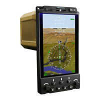
Astronautics RoadRunner AFI4700 Pilot's Manual (91 pages)
ELECTRONIC FLIGHT INSTRUMENT
Brand:
Astronautics
| Category:
Avionics Display
| Size: 3 MB
Table of Contents
Table of Contents
4
1 System Overview
9
System Description
9
Figure 1-1: System Description
9
System Power up
11
Figure 1-2: System Power up
11
System Operation
12
Figure 1-3: System Layout
12
Figure 1-4: System Menu
14
Using the System Menu
14
Figure 1-5: System Menu Navigation
16
Navigating the System Menu
16
Bezel Dimming Control
17
Display Dimming Control
17
Figure 1-6: Maintenance Menu Navigation
17
Navigating the Maintenance Menu
17
Night Vision Mode
17
Crosslink
18
Figure 1-7: Crosslink
18
2 Attitude Display Indicator Portion of Display
19
Indicator Description
19
Figure 2-1: ADI Description
19
Attitude Indicator
21
Figure 2-2: Attitude Indicator
21
Extreme Attitude
22
Radar Altimeter & Decision Height
22
Figure 2-3 Extreme Attitude
22
Figure 2-4: RA & DH
23
Figure 2-5: RA TST Annunciation
23
Autopilot Annunciation
24
Flight Director / Autopilot Modes
24
Figure 2-6: Autopilot Modes
24
Table 2-1: Flight Director Lateral Modes
24
Table 2-2: Flight Director Vertical Modes
25
Flight Director Display
26
Figure 2-7: FD Display
26
Approach Annunciation
27
Glideslope Indicator
27
Figure 2-8: GS Indicator
27
Lateral Deviation Indicator
28
Figure 2-9: Lat Dev Indicator
28
Expanded Localizer Mode
29
WAAS Annunciations
29
Figure 2-10: Expanded Localizer
29
Figure 2-11: WAAS Indicator
29
Rising Runway
30
Marker Beacon
30
Figure 2-12: Rising Runway
30
Table 2-3: Marker Beacon
30
Horizon Sync
31
Figure 2-13: Horizon Sync
31
Offside Indications
32
Figure 2-14: Offside Indications
32
Table 2-4: Offside Indications
32
Figure 2-15: Onside Attitude
33
Figure 2-16: Pilot Offside Attitude
34
Figure 2-17: Copilot Offside Attitude
35
Figure 2-18: Offside Attitude
36
Attitude Comparison Monitoring
37
Table 2-5: Attitude Miscompare Symbols
37
3 Horizontal Situation Indicator Portion of Display
38
Indicator Description
38
Figure 3-1: HSI Description
38
HSI Controls
41
Selecting an Active Navigation Source
41
Figure 3-2 Turn Rate Indication
41
Setting the Heading Bug
42
Changing Course
42
Figure 3-3: NAV Bezel Button Selections
42
Course Deviation Indicator
43
Figure 3-4: CDI
43
CDI Sources
44
Bearing Preview
44
Full Compass or Arc Mode Selection
45
Figure 3-5: Bearing Selections
45
Off Scale Indications
46
Figure 3-6: Bearing Preview
46
Figure 3-7: Off-Scale Indications
46
HSI Overlays
47
Bezel Button Operation
47
Figure 3-8: Bezel Button Selections
47
Left Bezel Button
48
Center Bezel Button
48
Table 3-1: Left Bezel Button Actions
48
Table 3-2: Center Bezel Button Actions
48
Right Bezel Button
49
Table 3-3: Right Bezel Button Actions
49
Bottom Center Buttons
50
Weather Radar
50
Figure 3-9: Map Range Ring Distance
50
Figure 3-10: Weather Radar Full Mode
51
Figure 3-11: Weather Radar Arc Mode
51
Weather Radar Patterns
52
Weather Radar Mode Annunciation
52
Weather Radar Vertical Mode
52
Table 3-4: Weather Radar Patterns
52
Table 3-5: Weather Radar Mode Annunciations
52
Figure 3-12: Weather Radar Vertical Profile
53
Figure 3-13: WX VP Menu
53
Lightening Detection
54
Figure 3-14: Lightening Detection
54
Figure 3-15: Lightening Detection Menu
54
Lightening Detection Symbology
55
Table 3-6: Lightening Detection Symbols
55
External Terrain Awareness and Warning System
56
Figure 3-16: External HTAWS
56
External HTAWS Terrain Color
57
Table 3-7: External HTAWS Terrain Color
57
External HTAWS Alerts
58
Table 3-8: HTAWS Alerts
58
Figure 3-17: FLTA Popup Alert
59
VOR Display
60
Figure 3-18: vor Map
60
Using the vor Map
61
Table 3-9: Intercepting a Radial
62
GPS Overlays
63
Figure 3-19: GPS Map
63
Figure 3-20: GPS CDI
64
Table 3-10: GPS Modes
65
Figure 3-21: GPS Map Bezel Button Selections
66
GPS Symbol Description
67
Table 3-10: GPS Map Symbols
67
TCAS Display
68
TCAS Symbol Description
68
Figure 3-22: TCAS
68
Figure 3-23: TCAS Symbol
69
TCAS Mode Annunciation
70
Figure 3-24: TCAS Modes
70
Table 3-11: TCAS Symbols
70
Offscale Intruders
71
Table 3-12: TCAS Modes
71
Table 3-13: TCAS Submodes
71
No Bearing Intruders
72
Figure 3-25: TCAS no Bearing
72
Heading Source Selection
73
Figure 3-26: Onside Heading
73
Figure 3-27: Pilot Offside Heading
74
Figure 3-28: Copilot Offside Heading
75
Figure 3-29: Offside Heading
76
Heading Miscompare Annunciations
77
Table 3-14: Heading Miscompare Annunciations
77
4 Messages
78
Visual Alerts
78
Table 4-1: Visual Alerts
78
5 Maintenance and Data Loading Page
85
6 Symbol Quick Reference
86
Map Symbols
86
Table 6-1: GPS Map Symbols
86
Lightening Detection Symbols
87
External TAWS Terrain Colors
87
Table 6-2: Lightening Detection Symbols
87
Table 6-3: External TAWS Terrain Colors
87
Weather Patterns
88
TCAS Symbols
88
Advertisement
Advertisement
Related Products
Astronautics Categories
Avionics Display
More Astronautics Manuals
Login
Sign In
OR
Sign in with Facebook
Sign in with Google
Upload manual
Upload from disk
Upload from URL