Table of Contents
Advertisement
Quick Links
Advertisement
Table of Contents

Summary of Contents for Astronautics RoadRunner AFI4700
- Page 1 PILOT’S GUIDE FOR THE AFI4700 ELECTRONIC FLIGHT INSTRUMENT (EFI) ASTRONAUTICS PN 276800-() To view Astronautics Certificate of Approval for this document, click here: http://www.astronautics.com/certificates Astronautics Corporation of America...
- Page 2 Revision History Description Date Author Initial Release 2018-10-02 G. Gruebling 1. Removed extraneous HTAWS. 2. Updated power up page. 3. Corrected image annotations. 2019-02-19 H. Faye 4. Removed RID/encoder text. 5. Clarified approach annunciation and figures. 1. Added marker beacon test section.
- Page 3 Description Date Author 3. Updated figure 3-12 to show rotary craft depiction. 4. Added GPS mode descriptions to section 3.3.6. 5. Updated figures 3-14, 3- 19, 3-20 and 3-22 for Time to Waypoint indication. 6. Changed EFI FAIL to CHECK EFI in table 4-1. 7.
-
Page 4: Table Of Contents
Table of Contents System Overview ................9 1.1 System Description ............... 9 1.2 System Power Up ............... 11 1.3 System Operation ............... 12 1.3.1 Using the System Menu ..........14 1.3.2 Navigating the System Menu .......... 16 1.3.3 Navigating the Maintenance Menu ........17 1.3.4 Display Dimming Control.......... - Page 5 3.3 HSI Overlays ................47 3.3.1 Bezel button Operation ........... 47 3.3.1.1 Left Bezel button ............. 48 3.3.1.2 Center Bezel button ............48 3.3.1.3 Right Bezel button ............49 3.3.1.4 Bottom Center buttons ............ 50 3.3.2 Weather Radar ..............50 3.3.2.1 Weather Radar Patterns ..........
- Page 6 Table of Figures Figure 1-1: System Description ............9 Figure 1-2: System Power Up ............11 Figure 1-3: System Layout ..............12 Figure 1-4: System Menu ..............14 Figure 1-5: System Menu Navigation ..........16 Figure 1-6: Maintenance Menu Navigation ........17 Figure 1-7: Crosslink................
- Page 7 Figure 3-16: External HTAWS ............56 Figure 3-17: FLTA Popup Alert ............59 Figure 3-18: VOR Map................ 60 Figure 3-19: GPS Map ................ 63 Figure 3-20: GPS CDI................. 64 Figure 3-21: GPS Map Bezel button Selections ......... 66 Figure 3-22: TCAS ................68 Figure 3-23: TCAS Symbol ..............
- Page 8 Table 6-4: Weather Radar Colors ............88 Table 6-5: TCAS Symbols..............88 AFI4700 Pilot’s Guide PLG12863E...
-
Page 9: System Overview
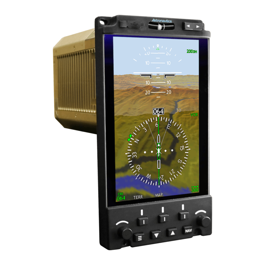
1 System Overview 1.1 System Description The Astronautics Flight Instrument (AFI) 4700 is a 5” by 7” Electronic Flight Instrument (EFI) designed to replace and improve upon the legacy electromechanical Attitude Director Indicator (ADI) and Horizontal Situation Indicator (HSI). Figure 1-1: System Description The AFI4700 is designed to interface with existing and/or retrofit attitude and heading units, navigation radios, GPS systems, etc. - Page 10 AFI4700 Pilot’s Guide PLG12863E...
-
Page 11: System Power Up
1.2 System Power Up Initial power up displays color bars on the screen. After several seconds, the color bars are replaced by the flight application. During aircraft power up, the display may start faster than other systems, such as gyros, resulting in a time delay between power-up and the system receiving valid signals. -
Page 12: System Operation
1.3 System Operation The AFI4700 is an EFI whose design consolidates the ADI and HSI information with the addition of Radar Altitude, Traffic Collision and Avoidance System (TCAS), Global Positioning Satellite (GPS), and VHF Omnidirectional Range (VOR) map overlays, display of Weather Radar, external Terrain Awareness and Warning System (TAWS), and a Physical Slip/Skid Indicator. - Page 13 navigation source. When navigating the menu, the left knob scrolls through the page selections. Right Rotary Knob The right rotary knob is used to adjust the selected heading. Rotating the knob moves the heading bug around the compass card and pressing the knob synchronizes the heading bug with the current heading.
-
Page 14: Using The System Menu
Navigation Source Select The lower right-hand bezel button allows the primary navigation source to be selected from the list of available navigation sources. Inclinometer In the center along the top bezel is a physical ball in a tube inclinometer, which displays slip or skid. USB Port The USB Port along the top of the bezel allows access to run maintenance and diagnostics on the EFI, as well as to update... - Page 15 DISP Change the compass between a full mode showing 360° and arc mode showing 120° with the left bezel button (ARC/FULL). When the weather overlay is selected, alternates between 360° compass and vertical profile mode with the center bezel button (VP). Provides an option to clear lightning icons when the map is displayed with the left bezel button (CLEAR).
-
Page 16: Navigating The System Menu
1.3.2 Navigating the System Menu After selecting the MENU bezel button, the MENU Page is displayed where six (6) pages can be cycled using the left rotary knob. Select the page items by using the left and center multifunction keys. Figure 1-5: System Menu Navigation AFI4700 Pilot’s Guide PLG12863E... -
Page 17: Navigating The Maintenance Menu
1.3.3 Navigating the Maintenance Menu When the MAINT option is selected from the System Menu, additional information is displayed in the EFI STATUS page. MAINT is only selectable when the aircraft is on ground. This page contains a further sub-menu from which maintenance related functionality can be accessed. -
Page 18: Crosslink
1.3.6 Crosslink When more than one display is installed, the AFI4700s will communicate with each other via an RS-422 serial interface crosslink bus. In order to provide assurance of data accuracy, the EFIs constantly compares attitude, heading, localizer, glideslope, and radar altimeter information between the two displays. -
Page 19: Attitude Display Indicator Portion Of Display
2 Attitude Display Indicator Portion of Display The Attitude Display Indicator (ADI) provides the pilot with primary flight display information. 2.1 Indicator Description Flight Director Flight Director Flight Director Flight Director Lateral Mode Roll Vertical Mode Vertical Mode Lateral Mode Active Pointer Active... - Page 20 Roll Pointer Scale Large tick marks indicate banks of 30° and 60° to the left and right with smaller tick marks indicating 10°, 20°, and 45°. Radar Altitude Indicates the current radar altitude from the radar altimeter. Decision Height Pilot selected decision height. Lateral Deviation Scale Four white dots indicate lateral deviation scale from the active navigation source input.
-
Page 21: Attitude Indicator
2.2 Attitude Indicator The primary purpose of the ADI is to display aircraft attitude information and provide flight direction cues. This is achieved by presenting a graphical format resembling a conventional electromechanical ADI ball. The ADI uses colors and symbols to orient the aircraft with the inertial frame of reference. -
Page 22: Extreme Attitude
aircraft’s pitch along the pitch ladder and roll along the roll angle scale within the ADI. 2.2.1 Extreme Attitude Figure 2-3 Extreme Attitude Extreme attitude is defined as a roll greater than 65°, 30° pitch up, or 20° pitch down. Red chevrons are displayed at +/- 50° and +/- 70° pitch up and pitch down respectively. -
Page 23: Figure 2-4: Ra & Dh
HDG bug. The decision height is displayed in green text when the aircraft is above the selected DH. Figure 2-4: RA & DH The Radar Altimeter is tested from the test menu. In the test menu, depressing the RA button for three seconds activates a discrete output to the RA unit to initiate the test. -
Page 24: Autopilot Annunciation
2.4 Autopilot Annunciation Autopilot status and mode information is displayed in two dedicated regions on the top edge of the display. Autopilot and flight director information are only available if the AFI4700 is configured to support the aircraft’s flight director and autopilot. 2.4.1 Flight Director / Autopilot Modes Figure 2-6: Autopilot Modes Flight Director validity is shown in the top left corner as “FD”. -
Page 25: Table 2-2: Flight Director Vertical Modes
Table 2-2: Flight Director Vertical Modes Armed Active Description Altitude capture mode Vertical speed climb or descend Indicated air speed climb or descend GPS navigation mode or GPS approach VGPS VGPS mode (vertical guidance) Glideslope capture mode Go around mode Autopilot modes are annunciated along the top of the display. -
Page 26: Flight Director Display
2.4.2 Flight Director Display Figure 2-7: FD Display The flight director display consists of two magenta bars overlaid on the ADI, which serve as a guide in orienting the aircraft flight path. The vertical bar is a heading cue (roll command), and the horizontal bar is a pitch cue. -
Page 27: Approach Annunciation
2.5 Approach Annunciation When an ILS approach is tuned by the selected NAV radio, the ADI changes functions to show annunciations relative to the approach. When performing an approach, tune NAV radio 1 and NAV radio 2 to the same approach ILS frequency. On final approach, select the runway course using the bezel course knob to ensure that the aircraft’s heading and runway course are the same. -
Page 28: Lateral Deviation Indicator
The glideslope deviation indicator is displayed to the right of the ADI when VOR is tuned to a valid ILS and is selected as the active NAV source. It appears as is shown in Figure 2-7 with four white dots and a green diamond. -
Page 29: Expanded Localizer Mode
2.5.3 Expanded Localizer Mode To support Category II approaches, an expanded localizer mode is displayed when the selected Decision Height is set to a value under 200 ft. The lateral deviation indicator is expanded, or zooms in, and the first dot to covers the entire lateral scale. To indicate this mode is different, bars are used in place of dots. -
Page 30: Rising Runway
2.5.5 Rising Runway Figure 2-12: Rising Runway The Rising Runway symbol provides an additional visual aid during landing. It consists of a virtual runway, which rises up from the very bottom of the ADI to the meet the aircraft reference symbol as the aircraft descends. -
Page 31: Horizon Sync
2.6 Horizon Sync When flying at a nose down attitude for extended periods, it becomes more difficult to determine slight changes in pitch attitude. Horizon Sync mode compensates for this by changing the current pitch attitude to zero and placing yellow tick marks where the pitch attitude used to be. -
Page 32: Offside Indications
2.7 Offside Indications When two displays are installed, each display is assigned “onside” navigation sources and “offside” navigation sources. Table 2-4: Offside Indications Nav Source Copilot Display Pilot Display VOR1 Offside Onside VOR2 Onside Offside GPS1 Offside Onside GPS2 Onside Offside Indicators that are affected by onside and offside coloring include navigation sources, lateral and vertical deviations, and course... -
Page 33: Figure 2-15: Onside Attitude
Attitude Source Selection A cockpit switch for each display selects attitude source. When operating normally, each switch is selected to onside attitude source. In the case of abnormal operation or a gyro failure, the pilot or copilot can select their EFI to display attitude from the offside source. ATT1 or ATT2 is annunciated in the top left corner of the ADI to indicate which side the attitude is sourced from. -
Page 34: Figure 2-16: Pilot Offside Attitude
Figure 2-16: Pilot Offside Attitude AFI4700 Pilot’s Guide PLG12863E... -
Page 35: Figure 2-17: Copilot Offside Attitude
Figure 2-17: Copilot Offside Attitude AFI4700 Pilot’s Guide PLG12863E... -
Page 36: Figure 2-18: Offside Attitude
Figure 2-18: Offside Attitude AFI4700 Pilot’s Guide PLG12863E... -
Page 37: Attitude Comparison Monitoring
2.8 Attitude Comparison Monitoring When a pitch, roll, or pitch and roll miscompare between both onside and offside attitude sources is detected, ATT is annunciated in the top left corner of the HSI. Table 2-5: Attitude Miscompare Symbols Symbol Description The pitch difference between onside and offside <->... -
Page 38: Horizontal Situation Indicator Portion Of Display
3 Horizontal Situation Indicator Portion of Display The Horizontal Situation Indicator (HSI) provides the pilot with horizontal situation information, navigation information, and graphical overlays. 3.1 Indicator Description The depiction below is the HSI in a “standard” view and tuned to a radio navigation source. - Page 39 Current Heading Always residing at the top of the compass card, the current heading indicates magnetic heading from the directional gyro. If the current heading is configured to display true heading, a small “T” appears to the right of the Current Heading box. Ownship A representation of the actual aircraft, this icon always points to the top of the compass card.
- Page 40 To-From Indicator Annunciated both as a white triangle on the course pointer and in white text, it shows whether the course pointer is pointed to or from the navigation source. Not available when selected to a GPS source. Active Navigation Source Displays the active navigation source, as selected by the NAV bezel button.
-
Page 41: Hsi Controls
Turn Rate Indication The EFI depicts turn rate as a magenta bar along the top of the compass card. Fixed reference marks indicate left/right 1.5°/second and 3°/second turns. The bar is capped with an arrowhead when the turn rate exceeds 4.5°/second left or right. Turn Rate is displayed on either the Full or Arc compass card. -
Page 42: Setting The Heading Bug
NAV Softkey PUSH VOR1 (Default) VOR2 GPS1 GPS2 Figure 3-3: NAV Bezel button Selections If a navigation source is not available, it will be annunciated in yellow with FAIL after the source name. 3.2.2 Setting the Heading Bug The heading bug is set by rotating the right rotary knob until the desired heading is selected. -
Page 43: Course Deviation Indicator
When GPS1 or GPS2 is the active navigation source, the selected course will be slaved to the active leg’s course and is unable to be changed by the left knob. This is indicated by changing the color of the readout and graphical depiction to magenta. 3.2.3.1 Course Deviation Indicator The course deviation indicator (CDI) consists of a bar that shifts left or right from the course pointer overlaid on four white dots and depicts... -
Page 44: Cdi Sources
3.2.3.2 CDI Sources VOR1 or VOR2 When the active navigation source is VOR1 or VOR2 and the aircraft is exactly aligned with the course radial, the deviation bar will be centered. The bar tracks left or right to indicate position to the left or right of the selected course. -
Page 45: Full Compass Or Arc Mode Selection
Figure 3-5: Bearing Selections If the configuration consists of a single VOR or GPS, the second source will be not be displayed. Likewise, if the system configuration only has a single ADF, then the DF option will not be displayed. 3.2.4 Full Compass or Arc Mode Selection The compass card can be changed to depict either a full 360°... -
Page 46: Off Scale Indications
Figure 3-6: Bearing Preview Full or Arc mode may be selected through the DISP page in the system menu. 3.2.5 Off Scale Indications When the HSI is displayed in ARC mode and the heading bug or bearing previews are to be shown outside of the field of view, the icons are drawn at the edge of the display closest towards their relative direction. -
Page 47: Hsi Overlays
3.3 HSI Overlays Map Overlay mode is available when valid data is provided by the selected navigation source. During map mode the course deviation indicator is suppressed and range rings are added at full scale (solid) and half scale (dashed). Overlay data can be selected from one or all of the following options: Left Softkey Center Softkey... -
Page 48: Left Bezel Button
3.3.1.1 Left Bezel button Table 3-1: Left Bezel button Actions Bezel Description button Text Default selection, white indicates no overlay is active Terrain Awareness and Warning System (TAWS) TERR overlay Weather Radar overlay Lightening Detection overlay LX+WX Lightening Detection and Weather Radar overlays Lightening Detection and Terrain Awareness and LX+TERR Warning System (TAWS) overlays... -
Page 49: Right Bezel Button
GPS Map overlay displaying active route GPS1 only. GPS2 GPS Map overlay displaying active route and RTE+STA GPS1 nearest navaids. GPS2 GPS Map overlay displaying active route and RTE+APT GPS1 nearest airports. GPS2 3.3.1.3 Right Bezel button Table 3-3: Right Bezel button Actions Bezel Description button Text... -
Page 50: Bottom Center Buttons
3.3.1.4 Bottom Center buttons The bottom center two bezel buttons adjust the map range for the HSI and the displayed overlays. The up arrow increases the range displayed and the down arrow decreases the displayed range. One- half of the full range is displayed on the on the inner ring, as seen in Figure 3-9. -
Page 51: Figure 3-10: Weather Radar Full Mode
Figure 3-10: Weather Radar Full Mode Figure 3-11: Weather Radar Arc Mode AFI4700 Pilot’s Guide PLG12863E... -
Page 52: Weather Radar Patterns
3.3.2.1 Weather Radar Patterns The weather radar signal returns are displayed on the HSI overlay according to intensity. Table 3-4: Weather Radar Patterns Color Precipitation Level Very Light (< 1 mm/hr) Light (1 – 4 mm/hr) Moderate (4 – 12 mm/hr) Strong (12 –... -
Page 53: Figure 3-12: Weather Radar Vertical Profile
The HSI changes formats to display the top half of the compass and a side view of the Weather Radar output. The range of this profile view is selectable using the bottom center bezel buttons, giving the full ranges of [2, 5, 10, 20, 40, 80, 16, 240, or 320 NM]. The inner three rings are ¼, ½, and ¾... -
Page 54: Lightening Detection
3.3.3 Lightening Detection The EFI interfaces with an Adaptive Passive Thunderstorm Detection System (APTDS) or Lightening Detection to provide storm cell and lightning information for thunderstorm monitoring. The EFI displays the electrical discharge information on the HSI using distance, bearing, and intensity information received from the Lightening Detection system. -
Page 55: Lightening Detection Symbology
3.3.3.1 Lightening Detection Symbology Different symbols are used to depict variances in lightning intensity from thin yellow, thick yellow with arrow, and thicker yellow with arrows, lightning bolts representing low, medium, and high intensity storm cells respectively. Table 3-6: Lightening Detection Symbols Symbol Intensity Unknown or Low (up to 8 strikes/minute) -
Page 56: External Terrain Awareness And Warning System
3.3.4 External Terrain Awareness and Warning System This section describes the visual display of terrain, terrain coloring, and annunciation of alerts. For specific operation and alert criteria, consult the guide for the connected HTAWS device. The AFI4700 supports interfacing with inputs from an external HTAWS or EGPWS, unit depending on the particular helicopter configuration. -
Page 57: External Htaws Terrain Color
3.3.4.1 External HTAWS Terrain Color Terrain is colored according to the following table. Table 3-7: External HTAWS Terrain Color Color Description Function Description Terrain/Obstacle Threat Area – Solid Red Warning Terrain/Obstacle Threat Area – Solid Amber Caution Terrain/Obstacle is more than 50% Red Dots 500 feet above aircraft altitude Terrain/Obstacle is between... -
Page 58: External Htaws Alerts
3.3.4.2 External HTAWS Alerts An external HTAWS device can drive different HTAWS alerts as shown in Table 3-8. The external device can also drive “Pop-Up” alerts, where the display automatically displays “ARC” mode when a threat criteria is met. A pop-up menu provides the option to “Revert Display”... -
Page 59: Figure 3-17: Flta Popup Alert
Figure 3-17: FLTA Popup Alert AFI4700 Pilot’s Guide PLG12863E... -
Page 60: Vor Display
3.3.5 VOR Display The VOR map function draws the active navigation source on the map overlay when the center bezel button is pressed. It is only available if bearing and distance to the station is provided by the navigation radio. When DME is not configured, the “MAP”... -
Page 61: Using The Vor Map
Active Navigation Source Displays the active navigation source, as selected by the NAV bezel button. VOR Map mode is only available when VOR1 or VOR2 is the active navigation source. Station A green navaid icon represents the station on a map. TO Course Line The solid green line extending from the station is the TO course line. -
Page 62: Table 3-9: Intercepting A Radial
Table 3-9: Intercepting a Radial Steps Using the CDI Using the VOR MAP Flying a course of 310° to intercept the 20° radial Radial inter- cepted, CDI is centered Right turn towards maintain- ing 20° radial AFI4700 Pilot’s Guide PLG12863E... -
Page 63: Gps Overlays
3.3.6 GPS Overlays The FMS/GPS map overlay presents the active flight plan to the pilot on the HSI if the FMS/GPS primary navigation source is selected. It is enabled by the center bezel button. Additional map elements (route, navaids, and airports) not on the active flight plan can be hidden from view by selecting the center bezel button. -
Page 64: Figure 3-20: Gps Cdi
When the FMS/GPS primary navigation source is selected and the CDI overlay is selected, the CDI will be displayed in place of the map. Figure 3-20: GPS CDI Ground Speed GPS derived ground speed is displayed in knots. Wind Vector Wind direction and magnitude are displayed relative to the aircraft’s orientation. -
Page 65: Table 3-10: Gps Modes
Distance to Waypoint The distance to the active waypoint is displayed in nautical miles. Active Navigation Source GPS1 or GPS2 will be annunciated here depending on the active source. GPS Mode The GPS indicates in which mode it is operating. Depending on the modes, CDI scaling may differ. -
Page 66: Figure 3-21: Gps Map Bezel Button Selections
Pressing the center multifunction bezel button cycles through the four available options to display GPS map data. (Default) RTE+STA RTE+APT Figure 3-21: GPS Map Bezel button Selections AFI4700 Pilot’s Guide PLG12863E... -
Page 67: Gps Symbol Description
3.3.6.1 GPS Symbol Description Map symbols and vectors are displayed as magenta or white. Magenta symbols and vectors represent the active waypoint. White symbols and vectors represent non-active waypoints. The various symbols used on the map overlay are presented below. Table 3-11: GPS Map Symbols Symbol Description... -
Page 68: Tcas Display
3.3.7 TCAS Display The EFI interfaces with a Traffic Alert and Collision Avoidance System (TCAS) to provide situational awareness through the depiction of traffic on the HSI. When operating normally, TCAS detects and displays traffic vertically between –2,700 ft and +2,700 ft of the aircraft. -
Page 69: Figure 3-23: Tcas Symbol
hundreds of feet and represent the absolute height above or below sea level. Heights below sea level are preceded with a ‘-‘. The Relative and Absolute modes have a few display characteristics in common. Both modes display the traffic aircraft altitude above its symbol if the traffic aircraft is above ownship or the traffic aircraft altitude is displayed below its symbol if the traffic aircraft is below ownship. -
Page 70: Tcas Mode Annunciation
Table 3-12: TCAS Symbols Symbol Description Other Traffic Traffic is greater than 1200 ft vertical separation and beyond 6 nm Proximate Traffic Traffic is less than 1200 ft vertical separation and within 5 nm Traffic Advisory TCAS criteria for a Traffic Advisory is met Resolution Advisory TCAS criteria for a Resolution Advisory is met. -
Page 71: Offscale Intruders
Table 3-13: TCAS Modes Modes Description The TCAS system indicates that only traffic TCAS advisories are available and resolution advisories are not available. TCAS The TCAS indicates test mode is active. TCAS The TCAS system indicates it is off. Table 3-14: TCAS Submodes Submodes Description The TCAS system indicates the altitude state is... -
Page 72: No Bearing Intruders
3.3.7.4 No Bearing Intruders When the TCAS is unable to track the bearing of an intruder, the EFI will display the TA distance, altitude, and trend next to the TCAS bezel legend. The EFI will display up to three No-Bearing intruders next to the TCAS button legend. -
Page 73: Heading Source Selection
3.4 Heading Source Selection A cockpit switch for each display selects the heading source. The pilot or copilot can select their EFI to display heading from either the same side or offside source. HDG1 or HDG2 is annunciated in the top left corner of the HSI to indicate which side the heading is sourced from. -
Page 74: Figure 3-27: Pilot Offside Heading
Figure 3-27: Pilot Offside Heading AFI4700 Pilot’s Guide PLG12863E... -
Page 75: Figure 3-28: Copilot Offside Heading
Figure 3-28: Copilot Offside Heading AFI4700 Pilot’s Guide PLG12863E... -
Page 76: Figure 3-29: Offside Heading
Figure 3-29: Offside Heading AFI4700 Pilot’s Guide PLG12863E... -
Page 77: Heading Miscompare Annunciations
3.5 Heading Miscompare Annunciations When a heading, lateral deviation, vertical deviation, miscompare between both left and right sources is detected, it is annunciated in the top left corner of the HSI. For a complete listing of warnings and cautions, see Section 4.1. Table 3-15: Heading Miscompare Annunciations Symbol Description... -
Page 78: Messages
4 Messages 4.1 Visual Alerts Table 4-1: Visual Alerts Message Description Crew Action An advisory message Switch the EFI attitude that occurs when both source selection switch ATT1 EFI displays are to choose independent configured to display attitude sources. This Attitude source attitude from the switch is found on the... - Page 79 Message Description Crew Action source differs by more than 6°. VOR is selected and Contact maintenance for communication from service and do not use CDI FAIL unit providing lateral VOR for navigation Navigation deviations is missing or invalid. In a dual EFI Contact maintenance for installation, the service.
- Page 80 Message Description Crew Action Mode 4a (FITNL) caution accompanied with an aural alert that says “Too Low Gear”. GPWS Mode 5: Correct vertical Excessive Downward deviation. GPWS Glide Slope Deviation (EDGSD) caution GPWS accompanied with an Mode 5 aural alert that says “Glide Slope”.
- Page 81 Message Description Crew Action Indicates both the Ensure both NAV radios localizer and glideslope are tuned to the same information from ILS1 frequency. If so, fly an <-> ILS and ILS2 differs by approach that does not Miscompare more than two-thirds of use the NAV radio and annunciation a dot deviation.
- Page 82 Message Description Crew Action GPS map information is Do not use GPS for missing or invalid. navigation. VOR1 or VOR2 is the Select a navigation MAP FAIL active navigation source with DME source and DME distance. distance is unavailable. Some crosslink Contact maintenance for MON DGRD communication...
- Page 83 Message Description Crew Action Indicates the roll Compare both EFI <-> ROL attitude from the onside displays and the standby attitude source and the attitude indicator for the Miscompare offside attitude source correct roll attitude. annunciation differs by more than 6°. Indicates when a Enable the Lightening lightning alert is present...
- Page 84 Message Description Crew Action portion of TCAS II but will display targets as red squares. The GPS unit indicates No action is necessary. a waypoint sequencing alert. Information received by Contact maintenance for the EFI from the service. WX CP FAIL weather radar control Do not use the weather Weather radar...
-
Page 85: Maintenance And Data Loading Page
MAINT in the menu while the aircraft is on-ground. Upon entering the maintenance mode, a list of installed software parts and Built In Test (BIT) results are viewable. For more information regarding maintenance or data loading, please contact an Astronautics dealer and/or refer to PLI12862. AFI4700 Pilot’s Guide... -
Page 86: Symbol Quick Reference
6 Symbol Quick Reference Note: The following tables describe the symbols that are located on the HSI Map displays. 6.1 Map Symbols Table 6-1: GPS Map Symbols Symbol Description Waypoint VORTAC TACAN VOR/DME (collocated) Airport Altitude Profile Point Intersection AFI4700 Pilot’s Guide PLG12863E... -
Page 87: Lightening Detection Symbols
6.2 Lightening Detection Symbols Table 6-2: Lightening Detection symbols Symbol Intensity Unknown or Low (up to 8 strikes/minute) Medium (9-25 strikes/minute) High (26 or more strikes/minute) 6.3 External TAWS Terrain Colors Table 6-3: External TAWS Terrain Colors Color Description Function Description Terrain/Obstacle Threat Area –... -
Page 88: Weather Patterns
6.4 Weather Patterns Table 6-4: Weather Radar Colors Symbol Description Very Light or None (< 1 mm/hr) Light (1 – 4 mm/hr) Moderate (4 – 12 mm/hr) Strong (12 – 50 mm/hr) Intense (> 50 mm/hr) Not Used Not Used Not Used 6.5 TCAS Symbols Table 6-5: TCAS Symbols... - Page 89 List of Acronyms Above Automatic Direction Finder Attitude Director Indicator Astronautics Flight Instrument ALRT Alert Altitude APTDS Adaptive Passive Thunderstorm Detection System Attitude Back Course Built-In Test Below BRGS Bearings Course Deviation Indicator Control Panel Difference in the Depth of Modulation...
- Page 90 Indicated Air Speed Instrument Landing System INOP Inoperative Localizer Light Emitting Diode LGPS Lateral Global Positioning System Loss of Integrity Longitude Lightening Detection Mode LX+TERR Lightening Detection + Terrain LX+WX Lightening Detection + Weather MAINT Maintenance Millimeters Monitor Message Navigation NCAT Negative Climb After Takeoff NVIS...
- Page 91 Vertical Profile Vertical Speed WAAS Wide Area Augmentation System Waypoint Weather Weather Radar AFI4700 Pilot’s Guide PLG12863E...
Need help?
Do you have a question about the RoadRunner AFI4700 and is the answer not in the manual?
Questions and answers