Sign In
Upload
Manuals
Brands
Astrid Manuals
UPS
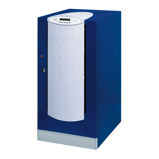
UPS HALLEY/E Series
Astrid UPS HALLEY/E Series Power Supply Manuals
Manuals and User Guides for Astrid UPS HALLEY/E Series Power Supply. We have
1
Astrid UPS HALLEY/E Series Power Supply manual available for free PDF download: Product Manual
Astrid UPS HALLEY/E Series Product Manual (56 pages)
20-80KVA
Brand:
Astrid
| Category:
UPS
| Size: 1 MB
Table of Contents
Uninterruptible Power Supplies
2
Table of Contents
3
1 Introduction
7
Environment
7
ISO 14001 Certification
7
Packing
7
Lead Battery
7
Treatment of the UPS at the End of Service Life
7
Safety Rules
7
Safety of Persons
7
Product Safety
7
Special Precautions
8
2 Ups General Description
9
Picture 1 - UPS Block Diagram
9
Rectifier / Battery Charger
10
Picture 2 - Rectifier
10
Operation with ONE Charging Level
11
Inverter
11
Picture 3 - Operation with ONE Charging Level
11
Picture 4 - Inverter
11
Operation with Non-Linear Load
12
Picture 5 - Diagram of the Power
12
Overload Management
13
Picture 6 - Operation with Non-Linear Load
13
Picture 7 - Thermal Image Characteristic
13
Short Circuit Operation
14
Picture 8 - Overload with Bypass Available
14
Picture 9 - Overload with Bypass Not Available
14
IGBT Bridge Protection
15
Picture 10 - Short Circuit Characteristic (By-Pass Not Available)
15
Picture 11 - IGBT Bridge Protection
15
Battery
16
Static Switch
16
Picture 12 - Static Switch and Manual By-Pass
16
Inverter Emergency Line Transfer
17
Emergency Line Inverter Transfer
17
Manual By-Pass
17
3 Operating Modes
18
Normal Operation
18
Picture 13 - Normal Operation
18
Battery Operation
19
Picture 14 - Battery Operation
19
Bypass Operation
20
Picture 15 - Bypass Operation (Manual Change-Over)
20
Picture 16 - Bypass Operation (Automatic Change-Over)
21
Manual Bypass
22
Picture 17 - Manual Bypass for Functional Tests
22
Picture 18 - Manual Bypass for Repair or Maintenance Works
23
4 User Interface (Front Panel)
24
Picture 19 - Front Panel
24
Alarms and Operating Status
25
Alarms
25
Status
26
Protections
26
Measurements on the Display
27
Menu Structure
28
Picture 20 - Menu Structure
28
5 General Technical Data
29
Technical Data Sheets
29
General Information
29
Rectifier
30
Inverter
31
Static By-Pass
31
Instructions for Installation
32
Receipt of the UPS
32
Handling of the UPS
32
Picture 21 - Handling of the UPS
32
Positioning and Installation
33
Base Plan, Static Load and Weights
33
Picture 22 - Base Plan
33
Dimensions and Distances
34
Picture 23 - Dimensions and Distances from the Walls
34
Electrical Connection
35
Terminal Board
35
Picture 24 - Terminal Board UPS 20-30Kva
35
Picture 25 - Terminal Board UPS 40÷80Kva
35
Battery Connection and Positioning
36
Picture 26 - Wiring 4 Batteries for Tray
36
External Battery
37
Picture 27 - Wiring 8 Batteries for Tray
37
Dimensions and Weights
38
Picture 28 - Dimensions of the External Battery Cabinets
38
Picture 29 - Base Plan of the External Battery Cabinets
38
Connections
39
Picture 30 - Battery Cabinets Connections
39
6 Options
40
Insulation Transformers
40
By-Pass Insulation Transformer
40
Rectifier Insulation Transformer
40
Voltage Adaptation Transformers
40
12-Pulse Rectifier
40
Ip31 Protection Degree
41
Special Paint
41
Fused Switch for the Battery
41
Picture 31 - Rectifier 12P with Galvanic Isolation
41
Connections
42
Technical Data
42
Picture 32 - Connection of the Battery Fused Switch
42
Remote Epo
43
Fans Monitoring
43
Diesel Generator Interface
43
Picture 33 - Diesel Generator Interface Block Diagram
43
Thermal Compensation Battery Charge
44
Boost Charge
44
Picture 34 - Charging Voltage Vs. Temperature
44
Picture 35 - BOOST Charge Diagram
44
Parallel Redundant Configuration
45
Picture 36 - Parallel Redundant Block Diagram
45
Arc - Free Voltage Contact Card
46
Additional Alarms (Int5Arc + 2Arc)
46
Picture 37 - ARC Card Layout
46
Remote Panel
47
Telephone Connection Kit
47
Picture 38 - Remote Panel Connection
47
Picture 39 - UPS-Modem Connection
47
Monitoring Software Voyager/E
48
Picture 40 - Voyager/E Screen
48
Ups Management Software
49
Additional Licenses for Ups Management Software
49
Snmp (Simple Network Management Protocol) Adapter
49
Jbus/Modbus Interface
49
Selection of the Ups-User Interface
50
7 Spare Parts List
51
Introduction
51
Spare Parts for Halley/E 20Kva
52
Level 1
52
Level 2
52
Level 3
52
Additional Spares
52
Spare Parts for Halley/E 30Kva
53
Level 1
53
Level 2
53
Level 3
53
Additional Spares
53
Spare Parts for Halley/E 40Kva
54
Level 1
54
Level 2
54
Level 3
54
Additional Spares
54
Spare Parts for Halley/E 60Kva
55
Level 1
55
Level 2
55
Level 3
55
Additional Spares
55
Spare Parts for Halley/E 80Kva
56
Level 1
56
Level 2
56
Level 3
56
Additional Spares
56
Advertisement
Advertisement
Related Products
Astrid HALLEY E
Astrid PLANET E
Astrid Categories
UPS
Toy
More Astrid Manuals
Login
Sign In
OR
Sign in with Facebook
Sign in with Google
Upload manual
Upload from disk
Upload from URL